Diagrams are provided for instances of a network master or an active network/job run. Diagrams can be used to view and edit a defined network or define a new network.
Note:
You can customize the diagram view by changing the
Diagram
settings in your user profile described in the
Administration documentation.
 To view a network diagram
In the object workspace, select a Network Master instance or an Active Run instance.
Open the context menu and choose the function.
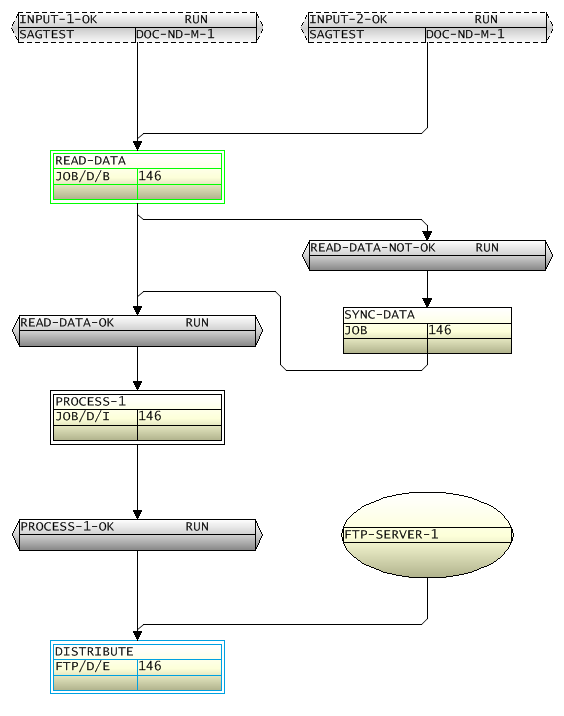
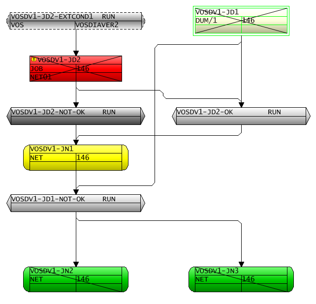
Depending on the node instance selected, a Diagram Network Master or Diagram Active Run window (see Examples of Diagrams) opens with a graphical view of the selected network.
The symbols used to represent the network components are described in Explanations of Diagram Symbols.
You can view and rearrange all network components as described in Maintenance Functions for Diagrams.
This document covers the following topics:
This section describes the symbols available in a diagram and indicates when a symbol only applies to an active job run.
The display of the symbols in the diagram graphic depends on whether
the Use new design option is set (default) in the user
profile (see the
Diagram
page described in Administration
documentation). In general, the new design is characterized by gradient symbol
colors and icons that identify specific reasons for an active job run that
ended not ok.
The information provided with a diagram symbol can exceed the size available to display text. In addition, a complex network can contain very small symbols impossible to read without zooming because the size of the diagram is adjusted to the size of the network. Therefore, tooltips for annotations are provided for all symbols so you can always view the complete information in a readable form.
| Symbol | Description | |
|---|---|---|
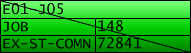
|
|
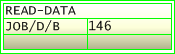
Job.
Common entries are
|
|
|
|
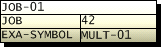
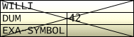
Multiple suffix job (here:
suffix symbol MULT-01 in the symbol table
EXA-SYMBOL).
|
|
|
|
Milestone job that performs as the
first network job.
In addition to the job special type, a milestone job has one or more (separated by slashes) of the following specifications: |
|
| User-defined milestone: | ||
B |
Milestone job, network begin | |
E |
Milestone job, network end | |
I |
Milestone job, other | |
| System milestone:
(used in active jobs only) |
||
1 |
Milestone job, network begin | |
2 |
Milestone job, network end | |
|
|
Milestone job that performs in no particular job order. | |
|
|
Milestone job that performs as the last network job. | |
|
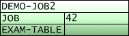
|
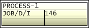
Job with type
Subnetwork
(NET), here named SUBNETJOB1.
|
|
|
|
Condition.
Indicates the condition name (here:
|
|
|
|
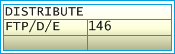
External condition (new
design) from another network.
Common entries are:
|
|
|
|
External condition (old design). | |
|
|
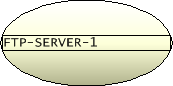
Resource
(here named FTP-SERVER-1).
|
|
|
|
Reset condition. | |
|
|
Set condition. | |
|
|
Successfully ended job. | |
|
|
Job waiting for execution.
(active run only) |
|
|
|
Job executed as a
temporary dummy for one of the
reasons described in Fields: Maintenance Job
Active (here: DS = dummy due to schedule definition).
(active run only) |
|
|
|
Running job.
(active run only) |
|
|
|
Job in hold or suspended
after changes to the job definition.
(active run only) |
|
|
|
Job ended not
ok.
(active run only) |
|
|
|
Job ended not
ok for one of the following reasons:
(shown in the new design and for the active job only) |
|
|
|
Job ended not
ok because network activation was cancelled by the user.
(shown in the new design and for the active job only) |
|
|
|
Job ended not
ok for any reason except
(shown in the new design and for the active job only) |
|
The background colors used for the symbols denote the following:
| Color | Explanation |
|---|---|
| yellow | The job waits for its execution. If the
allowed execution time is exceeded, the job is considered as ended not
ok and the symbol changes to red.
(active run only) |
| green | The job is currently executing.
(active run only) |
| light green | The active job is affected by
(active run only) |
| light yellow | The job ended ok.
|
| red | The job ended not ok, for
example, due to a JCL load error or an execution timeout.
(active run only) |
| light gray | The condition is set. |
| dark gray | The condition is not set. |
This section describes the functions available in a network diagram and indicates whether a function can be used only in a network master or an active run.
The following functions are available within the free space area of the diagram:
| Function | Description |
|---|---|
| Arrange | Rearranges the objects of the diagram automatically. |
| Refresh | Refreshes the presentation of the diagram. You can also use F5. |
| Auto Refresh | You can:
Note: |
| Object Filter | You may switch on/off:
Note: |
| Tooltip | You can customize the information
displayed in tooltip:
Note: |
| Find | Opens a search dialog where you can enter
a search string. You can also use CTRL+F.
See also To search for a string. |
| Find Next | Finds the next occurrence of a search
string entered in the search dialog. You can also use F3.
See also To search for a string. |
| Create Job | Adds a new job to the network. A Create new Job Master (see Adding a Job Definition) or Create new Job Active (active run only; see Adding a New Job to the Active Network) window opens to add a new job to the network. |
| Create Condition
(master only) |
Adds a new condition. Proceed as described in To add and link a condition. |
| Create Active
Condition
(active run only) |
Opens the Condition Active window to add a new active condition. |
| Paste
(master only) |
Paste a job object in the current network. See Pasting Objects. |
| Browse Log | Opens the Entire Operations log for the
network or active run shown in the active diagram window or a symbol selected
in the active diagram. The log only contains data relevant for this network or
run.
See also the Browse Log function that can be performed on a selected node in the tree view of the object workspace. |
| Page Setup | Opens a dialog where you can specify the page setup for printing the current diagram. |
| Printer Setup | Opens a dialog where you can specify your printer settings. |
| Print Preview | Opens a print preview where you can check if the diagram is laid out for printing according to your preferences. |
| Opens a dialog where you can send the diagram to a printer. | |
| Zoom | You have the following possibilities to
zoom the diagram:
|
| Show World View | Opens a separate window with a minimized view of the complete diagram for easy navigation in complex diagrams. The green frame outlines the current viewport in the associated diagram. You can move the green frame to change the viewport in the diagram. |
| Show Legend View | Opens a separate window with a minimized view of the symbols used in the diagram for a quick overview of the objects (for example, resources and conditions) used in the job network. |
| Export Graphic | Opens a dialog where you can save the diagram on your hard disk. |
The following functions are available for a job symbol selected in the diagram:
| Function | Description |
|---|---|
| Open | Displays the currently selected job (box) and opens the Job Master or Job Active (active run only) window. Here, you can perform changes on the job. |
| Display | Displays the currently selected job (box) in the Job Master or Job Active (active run only) window. |
| New | Creates a new job (box) and opens the Create new Job Master (see Adding a Job Definition) or Create new Job Active (active run only; see Adding a New Job to the Active Network) window. |
| Mass update
(master only) |
Changes the Execute if
temporary dummy option setting in End-of-Job actions for all jobs
currently selected in the diagram.
See also Changing Execute if Temporary Dummy Settings for Multiple Jobs. |
| Delete
(master only) |
Deletes the currently selected job (box). See Deleting Objects. |
| Copy data
(master only) |
Copies the currently selected job (box). See Copying Objects. |
| Paste data
(master only) |
Pastes the currently selected job (box). See Pasting Objects. |
| Usable Symbol Tables | Lists all symbol tables that can be used by the job. See also Listing Usable Symbol Tables in the section Symbol Table and Symbol Maintenance. |
| Deactivate
(active run only) |
You can cancel the planned activation of a job in a planned network run that is waiting for activation. |
| Hold
(active run only) |
If the job has already been submitted to the operating system, it will be held in the operating system. |
| Release
(active run only) |
Releases a job from hold status. |
| Cancel
(active run only) |
The active job is cancelled. |
| Resubmit
(active run only) |
After a job has terminated, you can modify and resubmit it while it is still in the active database. This function is useful after a job has failed. |
| Reactivate
(active run only) |
Reactivates a job. |
| Browse Master JCL
(master only) |
Browses the master JCL. See Displaying Master JCL. |
| Browse Active JCL
(active run only) |
A window opens where, you can see the actual JCL submitted to the operating system for execution. It is produced from the Master JCL when the job or network is activated. The symbols are replaced with values from the active symbol table. If it is dynamic JCL, the generation is performed at this time. The active JCL is stored in the active Entire Operations database. |
| Edit Master JCL
(master only) |
Edits the master JCL. See Editing Master JCL and Natural Sources. |
| Edit Active JCL
(active run only) |
A window opens where you can view and edit the active JCL of the job. |
| Regenerate Active
JCL
(active run only) |
Regenerates the JCL while the job is in the active database. |
| Stop cyclic execution
(active run only) |
Stops execution of currently running cyclic job. |
| Modify Latest Start
(active run only) |
See Modifying the Latest Start Time for an Active Run in the section Active Job Networks. |
| Release edit lock
(active run only) |
Removes a lock from active JCL: see Release edit lock in the section Active Job Networks. |
| Pregenerate Active
JCL
(master only) |
See Pregenerating Active JCL. |
| Remove pregenerated Active
JCL
(master only) |
See Removing Pregenerated JCL. |
| Edit pregenerated
JCL
(master only) |
See Editing Pregenerated JCL. |
| Browse SYSOUT
(active run only) |
A dialog opens were you can view the SYSOUT of an active job. See Viewing Job SYSOUT. |
| Extended Log / JCL
(active run only) |
A screen opens, where you can see the JCL which was submitted for this job. |
| Extended Log /
SYSOUT
(active run only) |
A screen opens, where you can see the SYSOUT of the job. |
| SYSOUT Messages
(active run only) |
A screen opens, where you can see the SYSOUT messages of the job (z/OS only). |
| Activate Job
(master only) |
Opens the Activation dialog where you can activate the currently selected job (box). |
| Open Subnetwork
(active run only) |
Opens the subnetwork Network Master dialog for a subnetwork (Job with type Subnetwork). |
| Subnetwork diagram | Opens the Network diagram for a subnetwork (Job with type Subnetwork). |
| Zoom Subnetwork | Opens a list of jobs for a subnetwork (Job with type Subnetwork). |
| Waiting for
(active run only) |
See Displaying Prerequisites for Active Jobs: Waiting for in the section Active Job Networks. |
| List Active Jobs | See Listing Active Jobs. |
| Browse Log | Opens the log for the currently selected job (box). See Displaying Logged Information - Browse Log Function. |
| Export
(master only) |
See Exporting Objects in the Import/Export Functions documentation. |
| Add to Workplan | Adds an object to the workplan. See also Add to Workplan. |
The following functions are available for the relationships (connecting lines) within the diagram:
| Function | Description |
|---|---|
| Set Input Condition
(active run only) |
Sets the input condition. |
| Reset Input
Condition
(active run only) |
Resets the input condition. |
| Delete
(master only) |
Deletes the currently selected relationships between the objects. |
| Open Network
(master only) |
Opens the corresponding network maintenance dialog (see Modifying a Network Definition) for an external input condition. |
| Network Diagram
(master only) |
Opens the corresponding network diagram and to position diagram view to the proper condition for an external input condition. |
| Open Input Condition
(master only) |
Opens the Condition dialog. Here, you can perform changes on the currently selected input condition. |
| Open Output
Condition
(master only) |
Opens the Condition dialog. Here, you can perform changes on the currently selected output condition. |
This section provides instructions for using the diagram editor functions to maintain objects for a network and find a particular object in the diagram.
From the context menu in the Diagram Network Master window, choose Create Condition.
A square symbol appears indicating the position where the new condition will be placed in the diagram.
In the free space of the diagram, left-click on the position where you want to place the new diagram symbol.
A Create Condition dialog appears.
Enter a valid condition name and choose OK.
The new condition is added to the diagram as a temporary (TMP) object, without any logical job links as shown in the tooltip information for the condition symbol.
Drag the selected condition and drop it onto the job to which you want to link the new condition as a logical input condition.
An Add new Input Condition window similar to the example below opens:
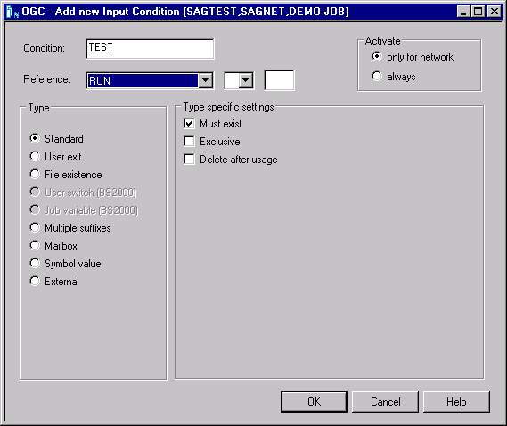
Enter the required definitions. The fields and options in the window are described in Fields and Selection Options: Input Condition in the section Job Maintenance.
When you are finished, choose OK.
The new condition is linked to the job as indicated by the connecting line between the job and the condition symbol and the tooltip information for the symbols.
To create an output condition
Select a job.
Drag the job and drop it onto a condition.
Select a branch (All Checks ok or Any Check not ok) to which the condition should be assigned.
To link two jobs
Select a job.
Drag the job and drop it onto a job.
Select a branch (All checks ok or Any check not ok) to which the condition should be assigned.
Call the search dialog by pressing CTRL+F or by choosing the function from the context menu:
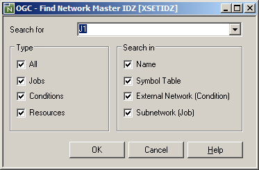
Fill in your search criteria. You can specify the search string, object type where the string is searched as well as the attribute of the object where to be searched. An asterisk ("*") is not interpreted as a wildcard.
Choose OK.