
This document covers the following topics:
Note:
The Active Run subnode of the
Network Master node correlates with the Active
Run subnode of the Network Active node. Both
subnodes control the same active runs. If you use both subnodes to change
active runs during a session, consider refreshing them manually to make sure
that you view the latest status.
Message and Message Recipients - Specifying Recipients for Network Messages
Granting Definition: Authorizing Other Users or Owners to Access a Network
![]() To list all networks defined for an owner
To list all networks defined for an owner
In the object workspace, select the Network Master node of an owner instance and choose List from the context menu.
Or:
Use the direct command
LIST
                                       NETWORKS
as described in the Direct
Commands documentation.
A Network Master List window similar to the example below opens:
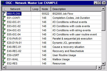
The window lists all networks defined for the selected owner.
For further information, see:
The Network Master List window contains the following columns:
| Column | Description | ||||
|---|---|---|---|---|---|
| Network | User-defined network name. | ||||
| Loop |
|
||||
| Node | Default execution node for the jobs in the network. | ||||
| Description | Short description of the network. |
![]() To list all available functions for the Network Master metanode
To list all available functions for the Network Master metanode
In the object workspace, select a Network Master metanode and open the context menu.
The context menu provides the following functions:
| Function | Shortcut | Description |
|---|---|---|
| List | F8 | See Listing All Network Definitions. |
| New | CTRL+N | Creates a new network master instance: see Adding a Network Definition. |
| Refresh | F5 | See Refreshing Object Lists. |
| Filter | F3 | Selection criteria for listing network masters: see Filtering Objects. |
| Paste data | CTRL+V | See Copying Job Network Definitions; Cloning Network Versions. |
| Export | --- | See Exporting Objects in the Import/Export Functions documentation. |
| Set Drag And Drop Function | --- | See Drag & Drop. |
![]() To list all available functions for a Network Master instance
To list all available functions for a Network Master instance
In the object workspace, select a Network Master instance and open the context menu.
The context menu provides the following functions:
| Function | Shortcut | Description |
|---|---|---|
| Open | CTRL+O | Modifies the selected network definition. |
| Display | CTRL+D | Displays the selected network definition. |
| Diagram | --- | Displays an overview of the job flow within this network. See Viewing and Maintaining a Job Network Diagram. |
| Delete | DELETE | Deletes the selected network, including all jobs and all other definitions for this network. |
| Copy data | CTRL+C | Copies all definitions of the selected network to paste them as a new network: see Copying Job Network Definitions; Cloning Network Versions. |
| Copy Defaults | --- | Copies network attribute definitions of the selected network as the default for all jobs contained in the network: see Applying Network Defaults to Jobs (Mass Update). |
| Activate Network | --- | Activates the selected network manually. |
| History | --- | Displays the execution history (previous network runs). |
| Display schedule | --- | Displays the schedule for a job network. |
| Next Activations | --- | See Displaying Next Network Starts - Next Activations in the section Schedule Maintenance. |
| Usable Symbol Tables | --- | Opens the Usable Symbol Tables window to view or modify all available symbol table definitions. See also Listing Usable Symbol Tables in the section Symbol Table and Symbol Maintenance. |
| Check for loop | --- | Checks for loops in the network. |
| Version Usage | --- | Maintains the usage of network versions. |
| List Active Jobs | --- | Lists active jobs defined for this network: see Listing Active Jobs. |
| Browse Log | --- | See Displaying Logged Information - Browse Log Function. |
| Export | --- | See Exporting Objects in the Import/Export Functions documentation. |
| Add to Workplan | --- | Stores a reference to the currently selected object in a list of activities to be done. See also Add to Workplan. |
| Set Drag And Drop Function | --- | See Drag & Drop Function. |
Displays job value, operating system special, symbol prompting and granting definition information for the currently selected Network Master.
The function invokes a dialog that displays the information for the currently selected network definition. You can only view the information, not edit it. If you want to edit the item, you have to use the function.
![]() To display a network definition
To display a network definition
In the object workspace, select an owner from the Owner node and then a network definition from the Network Master node.
Invoke the context menu and choose the function.
Or:
Press CTRL+D.
A Network Master window opens that displays all available information for the selected network definition.
The fields and tabs of the Network Master window are explained in Fields: Network Definition.
Opens job value, operating system special, symbol prompting and granting definition information for the currently selected network master in editing mode.
![]() To modify a network definition
To modify a network definition
In the object workspace, select a Network Master instance.
Invoke the context menu and choose the function.
Or:
Press CTRL+O.
A Maintenance Network Master window similar to the example below opens:
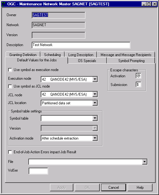
Now you can edit the fields you want to change.
The fields and tabs of the Maintenance Network Master window are explained in Fields: Network Definition.
Select .
Your changes are saved.
If your modification of a network schedule affects any planned starts, you have the option to cancel the starts or to keep them active.
If you select , a dialog similar to the example below appears:
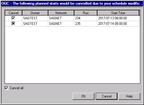
You can select the following functions:
Cancel all starts - by checking the box.
Cancel selected – by selecting certain planned runs in the table.
Do not cancel – by selecting the button. (Keeps all listed starts active, regardless of your schedule modifications).
![]() To create a new network master instance
To create a new network master instance
In the object workspace, select a Network Master instance.
Invoke the context menu and choose the function.
Or:
Press CTRL+N.
A Create new Network Master window similar to the example below opens:
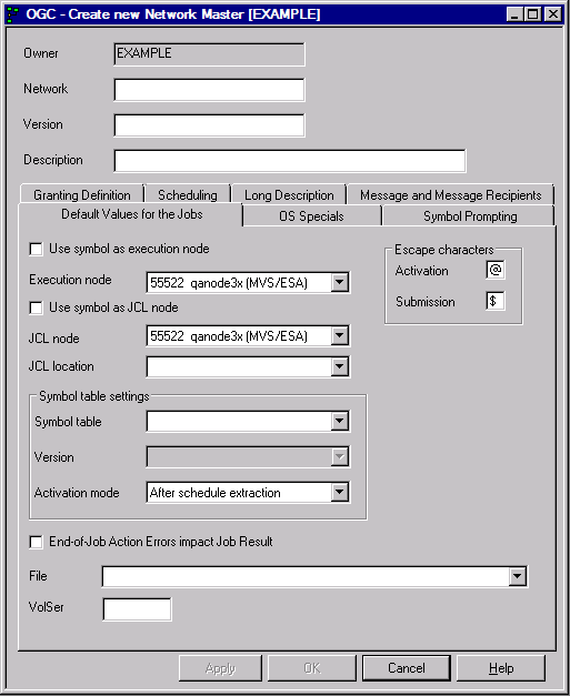
Now, you can insert the missing information into the fields.
The fields and tabs of the Create new Network Master window are explained in Fields: Network Definition.
Select .
Your changes are saved.
The fields and tabs of a Network Master window are described in the following table:
| Field/Tabbed Page | Description | ||||||||
|---|---|---|---|---|---|---|---|---|---|
| Owner | Owner of the network. | ||||||||
| Network | Network name. Together with owner name, uniquely identifies the network in the master database. | ||||||||
| Version | Network version.
You may add a new network with a non-blank version. It is possible to invoke the network addition multiply for the same network, but with different versions. New network versions can be created by cloning too as described in Copying Job Network Definitions; Cloning Network Versions. For further information on network versions, see Object Versioning in the Concepts and Facilities documentation. |
||||||||
| Description | Short description of the network.
This text appears in the list of networks in the Network
List window.
A longer description of the network can be added using the editor (see Documenting Your Networks). |
||||||||
| Default Values for the Jobs | The input fields on this tabbed page are used to specify default values for subsequent new job definitions in the network. Each default value specified here can be overridden at the job level. | ||||||||
| Use symbol as execution node | Mark this option if you want to use a suffix symbol: see the field Suffix symbol in the section Job Maintenance. | ||||||||
| Execution node | Default node ID on which jobs within this network are submitted. This value can be modified here or overridden at the job level. The drop-down list box shows all nodes available for selection. The operating system type appears after a valid node number. | ||||||||
| Use symbol as JCL node | Mark this option if you want to use a suffix symbol: see the field Suffix symbol in the section Job Maintenance. | ||||||||
| JCL node | Node on which JCL can be accessed.
The default is the same as for the Execution
node. The operating system type appears after a valid node
number.
The context menu of the selected node is the same as for Execution node. |
||||||||
| JCL location | Type of storage for the JCL: see
List of JCL
Locations.
The default is used in new job definitions and can be overridden there. |
||||||||
| Symbol table | Default symbol table for those jobs in the network that use the dynamic JCL generation facility. Can be overridden at the job level and is therefore optional here. The drop-down list box shows all symbol tables available for selection. | ||||||||
| Version
(symbol table) |
You can maintain several versions
of a symbol table.
The drop-down list box shows all symbol table
versions available for selection.
Reserved names:
For further information, see Object Versioning in the Concepts and Facilities documentation. |
||||||||
| Activation mode
(symbol table) |
From the drop-down list box you can
choose either of the following:
|
||||||||
| Activation
(escape characters) |
Activation Escape Character =
Network default value
This escape character is the prefix for Natural code lines and symbols to be replaced at activation time. Caution: |
||||||||
| Submission
(escape characters) |
Submission Escape Character =
Network default value
This escape character is the prefix for Natural code lines and symbols to be replaced at submission time. Caution: |
||||||||
| End-of-Job Action Errors impact Job Result | If you select
this check box, output condition(s) are set for the job after all
end-of-job actions are performed. This includes end-of-job action (EJA) exits.
Any errors in the end-of-job action processing will cause the setting of the
conditions for job not ok. If the job was already set to not
ok, it will remain not ok, regardless of the definition
here.
Notes:
If the check box is not selected, errors during end-of-job action processing will have no impact on the job result. Job level: If the field is empty, the network level definition will be inherited at activation time. This is the default. |
||||||||
| File | Name of the file or Natural library
according to the value of the JCL Location field.
For BS2000: The default pubset will be stripped from the file name prior to storing it. This allows easier migration to another default pubset. |
||||||||
| VolSer | Volume serial number of data set (if data set is not cataloged). | ||||||||
| OS Specials | This tabbed page is described in OS Specials - Operating System and Environment Defaults. | ||||||||
| Symbol Prompting | This tabbed page is described in Symbol Prompting during Network or Job Activation in the section Symbol Table and Symbol Maintenance. | ||||||||
| Granting Definition | This tabbed page is described in Granting Definition: Authorizing Other Users or Owners to Access a Network. | ||||||||
| Scheduling | This tabbed page is described in Scheduling a Network in the section Schedule Maintenance. | ||||||||
| Long Description | This tabbed page is described in Long Description - Documenting Your Networks. | ||||||||
| Message and Message Recipients | This tabbed page is described in Message and Message Recipients - Specifying Recipients for Network Messages. | ||||||||
![]() To specify operating system specific defaults
To specify operating system specific defaults
Select the OS Specials tab.
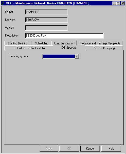
Select the required operating system.
Depending on the operating system/environment selected, different input fields are provided on the page as shown in the example of z/OS below:
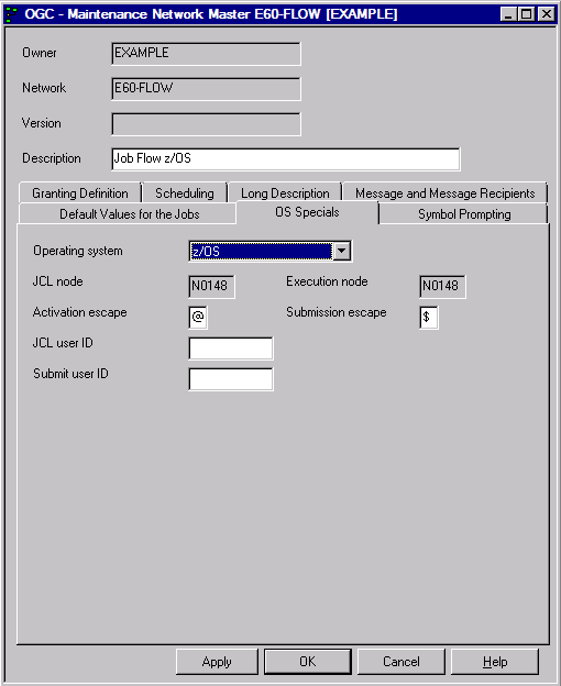
For information on all fields available, see Input Fields: Network Defaults.
Select .
This section covers the following topic:
The input fields available on the tabbed page OS Special depend on the operating system selected as indicated in the following table:
| Field | Description |
|---|---|
| Operating system | Operating system/environment:
BS2000, z/OS, z/VSE, UNIX/Windows or SAP R/3. |
| Activation escape | Activation Escape Character =
Network default value specific for operating system
This escape character is the prefix for Natural code lines and symbols to be replaced at activation time. Caution: |
| Submission escape | Submission Escape Character =
Network default value specific for operating system
This escape character is the prefix for Natural code lines and symbols to be replaced at submission time. Caution: |
| JCL User ID | (Not applicable to z/VSE)
The user ID to be used for JCL loading |
| BS2000:
If this field is not empty, the JCL is loaded with the rights of this BS2000 user ID. It can be overwritten with specific definitions. TSOS may only be defined if the user himself has logged on under TSOS. Default: The user ID from the fully qualified file name. If this field is left empty in a job definition, then the Default User ID will be inserted during the activation of the job. |
|
|
z/OS: JCL in z/OS will be loaded under this user ID by the Entire Operations Monitor. You can define this field only if you are logged on to the JCL node with the same user ID. Default: If this field is left blank, the user ID of the last modification will be used as JCL user ID. |
|
|
UNIX and Windows: With the authorization of this user ID, the Entire Operations Monitor loads the JCL of type TXT. |
|
|
See also the default setting User ID Definition (Defaults for Other Settings, Administration documentation), Operating System User IDs and Default User ID Determination. |
|
| Submit User ID | (Not applicable to z/VSE)
The user ID to be used at job start |
| BS2000:
The Entire Operations Monitor starts jobs in BS2000 under this user ID. In the network definition, this is a default value for the jobs. If this field is left empty in a job definition, then the Default User ID is inserted during the activation of the job. |
|
|
z/OS: The Entire Operations Monitor starts jobs in z/OS under this user ID. You can only define this user ID if you have logged on to the executing node with the same user ID.Default: If this field is empty, the user ID of the last modification is taken as submit user ID. |
|
|
UNIX and Windows: With the authorization of this user ID, the Entire Operations Monitor starts the script or the executable program. |
|
|
See also the default setting User ID Definition (Defaults for Other Settings, Administration documentation), Operating System User IDs and Default User ID Determination. |
|
| Applies to BS2000 only: | |
| Default User ID | This user ID is a default for all objects of this job network or job which are linked to a user ID. |
| Job Class | This job class is a default for all jobs in the network. It can be overridden by specific definitions. |
| Account Number | This account number is a default for the Submit User ID defined for the job network. It can be overridden by specific definitions. |
| Job Priority | If not empty, this job priority will be used during submission and will override a possible setting in the LOGON statement. The default value on network level will be used for new job definitions. |
| Run Priority | If not empty, this run priority will be used during submission and will override a possible setting in the LOGON statement. The default value on network level will be used for new job definitions. |
| SYSOUT User ID | This is the user ID under which
internal SYSOUT files are created by Entire Operations. If you do not enter an
ID here, the Submit User ID is used.
See also the default setting User ID Definition (Defaults for Other Settings, Administration documentation), Operating System User IDs and Default User ID Determination. |
| SYSOUT Cat ID | This is the catalog ID under which internal SYSOUT files are created by Entire Operations. This field is meaningful only if a SYSOUT user ID different from the submit user ID is used. |
| Applies to UNIX and Windows only: | |
| JCL Group |
Applies to UNIX only (optional) If this field is left blank, the standard group of the UNIX user ID is used as defined under/etc/passwd. Otherwise, this field must contain one of the groups
issued by the UNIX command groups.
|
| Submit Group |
Applies to UNIX only (optional) If this field is left blank, the standard group of the UNIX user ID is used as defined under/etc/passwd. Otherwise, this field must contain one of the groups
issued by the UNIX command groups.
|
| Applies to SAT only: | |
| System ID | SAP System ID (SID), as required by jexa4S. |
| System Number | SAP System Number, as required by jexa4S. |
| Client | SAP Client
Symbol replacement is possible (except at logon). |
This function is used to specify single or multiple users to receive network-related messages that are sent when a specified event occurs. This is especially useful for sending information about the abnormal end of a job.
Among the events, which can cause a message to be sent, are:
a calendar not defined for next year;
a network not correctly terminated;
symbol prompting requests.
The specific message text is generated automatically by the Entire Operations Monitor.
![]() To define a message recipient
To define a message recipient
Select the Message and Message Recipients tab.
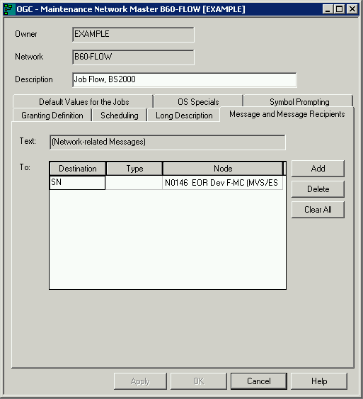
Insert a text and a destination for the message.
For further information, refer to Fields and Columns: Message and Message Recipients in the section Message Sending.
Select .
Entire Operations allows you to authorize other users and owners to access a network that belongs to you.
Users grouped under the owner SYSDBA have unlimited access to all networks in the system. They do not need the authorization described in this section.
Users and linked owners (lower than administrator) have limited access rights to granted networks in accordance with the rights specified in their user profiles and the restrictions specified in their individual network granting definition.
The Owner via Granting metanode lists all owners who granted network access for your user ID: see Listing Granted Owners in the section Using Owners.
![]() To add or modify a granting definition
To add or modify a granting definition
In the Network Master window, open the tabbed page Granting Definition.
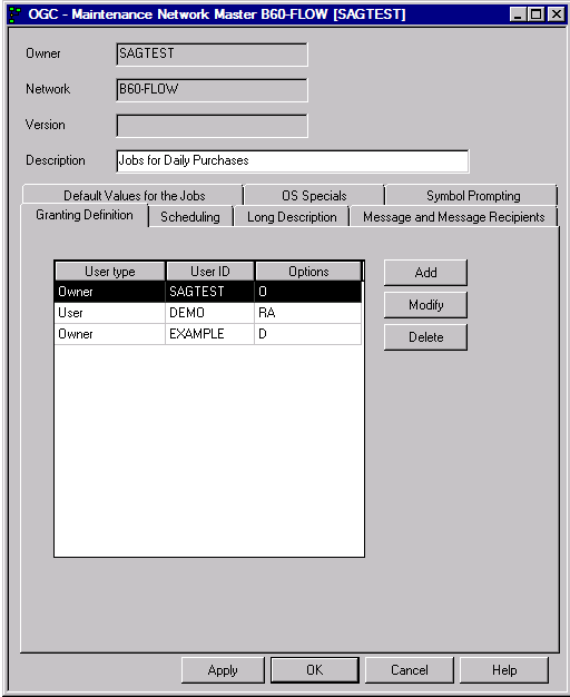
Select a user type.
Select the button.
A Granting Definition window similar to the example below opens:
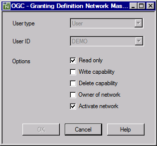
Specify the rights for the previously selected user. The fields and options available are described in Fields: Granting Definition.
Select .
![]() To delete a granting definition
To delete a granting definition
On the Granting Definition page, select the table row that contains the user or owner whose granting definition you want to remove and choose Delete.
A window prompts you to confirm the deletion.
Choose Yes to confirm the deletion (No cancels the action) and close the window.
Choose OK to save your changes.
The users and owners you can remove depend on your user authorization. For the delete restrictions that apply, see Deleting a User/Owner Link in the Administration documentation.
The columns on the Granting Definition page and the corresponding fields and options in the Granting Definition window are described in the following table:
| Column/Field | Description | |
|---|---|---|
| User Type | Specifies the object to be authorized. Possible options: | |
| Owner | All users linked to the Entire Operations owner specified in the User ID field. | |
| User | A defined user. | |
| User ID | The user or owner to be granted
access. If the access rights are given to an owner, all linked users can obtain
these access rights.
You can select a user from the drop-down list box. |
|
| Options | Level of access granted to a user
or owner.
You can select one or more of the following authorization levels: |
|
| Read only | Read access to the network (no maintenance). | |
| Write capability | Read and write access to the network (maintenance allowed except delete network). | |
| Delete capability | Read, write and delete access to the network. | |
| Owner of network | Read, write and delete access to the network. In addition, the specified user or owner can also allow network access to other users and owners. | |
| Activate network | User is allowed to activate the network. | |
You can add a brief description of a job network when defining a network in the Network Master window. This short description appears in the list of networks in the Network Master List window.
If you wish to add more online documentation for a network, you can invoke the Entire Operations editor.
![]() To create or modify a detailed description for a job master
To create or modify a detailed description for a job master
Select the Long Description tab.
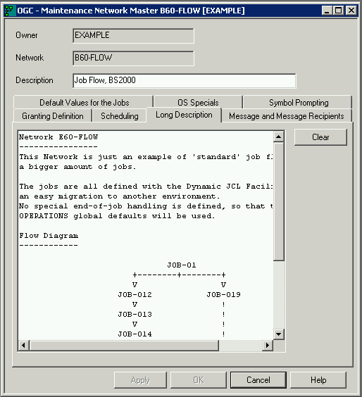
Write an explanation concerning the network master.
Select .
Only authorized users can delete a network. Only networks without active runs and version usage can be deleted.
Deleting a network also deletes all definitions made for the network on lower levels using network and job maintenance functions.
Entire Operations saves the last run number of a deleted network. The first run of a new network under the same name receives the last run number incremented by 1.
![]() To delete a network
To delete a network
In the object workspace, select an owner from the Owner node and then a network definition from the Network Master node.
Invoke the context menu and choose the function.
Or:
Press Delete.
A dialog prompts you to confirm the delete request.
Choose Yes.
If the delete is rejected, you receive an appropriate error message on the reason.