This document describes how to start and shut down the Data Mapping Tool and provides an overview of the Data Mapping Tool interface. It covers the following topics:
![]() To start the Data Mapping Tool in Windows environments, complete the following
steps:
To start the Data Mapping Tool in Windows environments, complete the following
steps:
Select from the Start Programs submenu.
Or:
Locate and run the MappingTool.exe file in the
installation directory.
The Data Mapping Tool starts up and it primary window appears.
![]() To start the Data Mapping Tool in UNIX environments, complete the following
steps:
To start the Data Mapping Tool in UNIX environments, complete the following
steps:
Run the MappingTool.sh file in the installation directory.
The Data Mapping Tool starts up and it primary window appears.
![]() To shut down the Data Mapping Tool:
To shut down the Data Mapping Tool:
Click the button on the Data Mapping Tool window.
The Data Mapping Tool shuts down.
This section describes the Data Mapping Tool window, menus, and buttons. It covers the following topics:
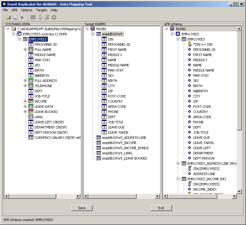
The Data Mapping Tool main window is divided into three columns.
The far left column, SYSTRANS DDMs, lists available DDMs. Once you have identified a directory containing DDMs, the DDMs in that directory get listed in this column. For information on identifying the directory containing your DDMs, read Locating and Selecting a Source DDM.
The middle column, Target RDBMS, lists the target relational database tables to which you will map fields from your DDM. To add and remove target relational databases from this list, read Adding a Target Database.
The right column, GFB Schema, displays the GFB schema that is created when you drag a DDM onto an RDBMS. A GFB and field table (GFFT) can be generated from this schema.
The Data Mapping Tool main window includes five menus. The options available from these menus are described in this section:
The menu consists of the following menu options:
| Menu Option | Description |
|---|---|
| Allows you to specify the directory in which data definition modules (DDMs) can be found. For more information, read Locating and Selecting a Source DDM. | |
| Allows you to save the RDBMS target table and GFB schema listed on the screen. The next time you start up the Data Mapping Tool, this table and GFB schema will automatically appear. | |
| Allows you to shut down the Data Mapping Tool. |
The options on the menu only become available once a GFB schema appears in the GFB Schema column of the screen. It consists of the following menu options:
| Menu Option | Description |
|---|---|
| Allows you to redefine a field in the schema. For more information, read Redefining Schema Fields. | |
| Allows you to specify that a field selected in the schema is the primary key or is part of a composite key. For more information, read Specifying Keys. | |
| Allows you to specify that a field selected in the schema is no longer the primary key or part of a composite key. For more information, read Specifying Keys. | |
| Allows you to generate the GFB and field table, based on the selected GFB schema. For more information, read Generating a GFB and Field Table. |
The menu consists of the following menu options:
| Menu Option | Description |
|---|---|
| Allows you to set the logging level for Data Mapping Tool processing. For more information, read Managing Logging and Log Files. | |
| Allows you to specify the default number of occurrences of repeating elements for each MU or PE field if you want them to be flattened during replication. When you drag a DDM onto an RDBMS target to create a GFB schema, you are presented with a panel on which you can override this default for each MU or PE field. For more information, read Requesting MU and PE Field Flattening During Replication | |
| Allows you to specify the file extensions of the DDMs you want to see in the leftmost column of the Data Mapping Tool main window. |
The menu consists of the following menu options:
| Menu Option | Description |
|---|---|
| Allows you to add and link to a target RDBMS. Once added, the RDBMS is listed in the middle column of the Data Mapping Tool main window. For more information, read Adding a Target Database. |
The menu consists of the following menu options:
| Menu Option | Description |
|---|---|
| Allows you to access the online help for the Data Mapping Tool | |
| Lists version information about this installation of the Data Mapping Tool. |
The Data Mapping Tool main window includes the following buttons:
Note:
Some of these buttons only become useable if specific items are
selected in the Data Mapping Tool screen.
| Button | Description |
|---|---|
 |
Allows you to specify the directory in which data definition modules (DDMs) can be found. For more information, read Locating and Selecting a Source DDM. |
 |
Saves the current mappings shown in the Data Mapping Tool. Target definitions in the target list, GFB schemas, and source DDMs are saved. |
 |
Exits the Data Mapping Tool. |
 |
Allows you to redefine the selected GFB schema field. For more information, read Redefining Schema Fields. |
 |
Allows you to specify that a field selected in the schema is the primary key or is part of a composite key. For more information, read Specifying Keys. |
 |
Allows you to specify that a field selected in the schema is no longer the primary key or part of a composite key. For more information, read Specifying Keys. |
 |
Allows you to generate the GFB and field table, based on the selected GFB schema. For more information, read Generating a GFB and Field Table. |
 |
Exits the Data Mapping Tool. |
 |
Saves the current mappings shown in the Data Mapping Tool. Target definitions in the target list, GFB schemas, and source DDMs are saved. |
The button allows you to save the RDBMS target table and GFB schema listed on the screen. The next time you start up the Data Mapping Tool, this table and GFB schema will automatically appear.
The button allows you to shut down the Data Mapping Tool.
The Data Mapping Tool main window uses the following icons:
| Icon | Description |
|---|---|
 |
Identifies a DDM file in the leftmost pane. |
 |
Identifies a DDM in the leftmost pane, an RDBMS table in the center pane, and a GFB schema table in the rightmost pane. In addition, this icon precedes the and options on the right-click menu of an RDBMS or table in the center pane. |
 |
Identifies a simple field in the leftmost pane and an RDBMS column in the center pane. In addition, this icon precedes the and options on the right-click menu of a table in the center pane. |
 |
Identifies a multiple value (MU) field in the leftmost pane. |
 |
Identifies a flattened multiple value (MU) field in the leftmost pane. |
 |
Identifies a periodic group (PE) field in the leftmost pane. |
 |
Identifies a flattened periodic group (PE) field in the leftmost pane. |
 |
Identifies a simple group field in the leftmost pane. |
 |
Identifies a subfield or superfield with occurrences in the leftmost pane. |
 |
Identifies a flattened subfield or superfield with occurrences in the leftmost pane. |
 |
Identifies a subfield or superfield with MU or PE occurrences in the leftmost pane. |
 |
Identifies a flattened subfield or superfield with MU or PE occurrences in the leftmost pane. |
 |
Identifies an RDBMS database in the center and rightmost panes. This icon also precedes the option on the menu. |
 |
Identifies a GFB schema in the rightmost pane.
In addition, this icon:
For more information, read Generating a GFB and Field Table. |
 |
Identifies a GFB schema field in the rightmost pane. |
|
Identifies a GFB schema key field -- either the
primary key or a field included in a composite key -- in the rightmost pane. In
addition, this icon:
For more information, read Specifying Keys. |
 |
Precedes the option on the right-click menu of a GFB schema composite key field in the rightmost pane. |
|
Precedes the option on the right-click menu of a GFB schema key field in
the rightmost pane. This icon also:
|
 |
Identifies a GFB schema foreign key in the rightmost pane. |
 |
Precedes the option on the right-click menu of a DDM field in the leftmost pane. For more information, read Flattening Fields for Replication. |
 |
Precedes the option on the right-click menu of a DDM field in the leftmost pane. For more information, read Flattening Fields for Replication. |
 |
Precedes the option on the right-click menu of a GFB schema or GFB schema field in the rightmost pane. |
|
Precedes the
option on the right-click menu of a GFB schema field in the rightmost pane.
This icon also:
For more information, read Redefining Schema Fields. |
 |
Identifies a child field of a redefined (split) field in the rightmost pane. |
|
Appears on a button that allows you to save the current mappings shown in the Data Mapping Tool. This icon also precedes the option on the menu. |
|
Appears on a button that allows you to specify the directory in which data definition modules (DDMs) can be found. This icon also precedes the option on the menu. |
 |
Precedes the option on the right-click menu of a screen element. |
|
Appears on a button that allows you to exit the Data Mapping Tool. This icon also precedes the option on the menu. |
 |
Precedes the option on the right-click menu of a screen element. |
 |
Precedes the option on the menu. This option allows you to access the online help for the Data Mapping Tool. |