This document covers the following topics:
Scenario: "I have a Natural server subprogram and want to call this from a REST client."
This scenario uses the tools IDL Extractor for Natural and Integration Server Wrapper of the Designer.

Solution: Take an existing Natural server subprogram  and
generate the integration logic
  to call it from a REST client
  , as shown below.

 |
Extract the interface of the Natural server program. See Using the Software AG IDL Extractor for Natural. |
 |
Generate REST resources, connection and adapter services in Integration Server. |
 |
Execute the call from the REST client to the Natural server program. |
This scenario makes the following important assumptions:
You have a working Natural subprogram, also known as a CALLNAT program.
You have access to the sources of this Natural subprogram. These must be stored either
locally, that is, on the same machine where NaturalONE is running

or remotely and accessed via the Natural RPC Server (1), and either EntireX Broker or Integration Server.

Instead of NaturalONE, you can also use the Designer.

(1) See your Natural documentation for setting up the Natural RPC Server.
You have an Integration Server with EntireX Adapter installed.
You have a REST client.
You can call the Natural server subprogram at runtime using different methods:
For the EntireX RPC connection method you need
EntireX Broker on one of the supported platforms: z/OS | UNIX | Windows | BS2000 | z/VSE
the Natural RPC Server (1)

For the EntireX Direct RPC connection method you need:
the Natural RPC Server (1)

(1) See your Natural documentation for setting up the Natural RPC Server.
Follow the instructions for extracting Natural under Using the Software AG IDL Extractor for Natural:
If your Natural sources are stored locally and you are using NaturalONE, see Extracting IDL from Natural Subprogram Sources in NaturalONE.
If your Natural sources are stored remotely and this is your first extraction, see Extracting Software AG IDL File from a New Natural RPC Environment; for subsequent extractions see Extracting Software AG IDL File from an Existing Natural RPC Environment.
This process creates the following EntireX metafiles:
IDL file. A Software AG IDL file contains definitions of the interface between client and server. See Software AG IDL File in the IDL Editor documentation.
Server mapping file (optional). The mapping file is a Designer file with extension .cvm that contains Natural-specific mapping information. See Server Mapping Files for Natural in the Designer documentation.
The following Natural server is used to illustrate the features of the IDL Extractor for Natural.
Imagine an existing Natural server called EMPLOYEE.
It implements the access logic for a LIST and DETAILS function to a database view EMPLOYEE.
Its parameter data area is shown below:
DEFINE DATA PARAMETER
1 OPERATION        (A1)    /* 'L' => List; 'D' => Details
1 ID               (A10)   /* Input
1 EMPLOYEE                 /* Output
  2 FIRSTNAME      (A20)   /* First name
  2 SURNAME        (A20)   /* Surname
  2 DATE-BIRTH     (D)     /* Date of birth
  2 DETAILS        (A100)
  2 REDEFINE DETAILS
    3 ANNUAL-SALARY(P9)    /* Annual salary
    3 VACATION     (N2)    /* Vacation days per year
    3 LANGUAGE     (A3)    /* Language
1 EMPLOYEES        (1:*)   /* Out
  2 IDENT          (A10)   /* Identification number
  2 FIRSTNAME      (A20)   /* First name
  2 SURNAME        (A20)   /* Surname
  2 DATE-BIRTH     (D)     /* Date of birth
END-DEFINE
Two approaches for extracting the Natural server are described below:
Fast-track
Learn how EntireX helps you to connect the Natural Server with quick results, even without specific Natural knowledge. See
Extracting a Natural Server - Fast-track Method.
User-defined Mapping
With a user-defined mapping, you can shape the interface to your Natural server.
You can minimize the interface by suppressing Natural server fields or by providing constant values.
Renaming interfaces allows you to specify a readable long name.
These two features together - constants and renaming of interfaces - are most powerful when multiple interfaces are implemented
in a single Natural server.
Each function of the Natural server triggered by an operation code or function code can be modelled as a separate REST resource
method/operation.
See Extracting a Natural Server - Modern Method with User-defined Mapping.
 To extract the Natural server
Switch to the EntireX perspective.
Invoke the IDL Extractor for Natural.
Select the Natural server subprogram, in this example EMPLOYEE, and press .
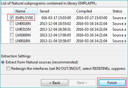
The default extraction settings ensure you get useful results. The outcome is a Software AG IDL file (interface definition language), a Designer file with extension .idl:
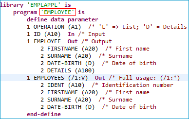
By default, the interface name EMPLOYEE is taken from the Natural server subprogram name.
EntireX allows you to extract all implemented interfaces of the Natural server separately.
Instead of a large EMPLOYEE interface, separate interfaces getListOfEmployees and getDetailsOfEmployee are extracted.
Each interface contains required parameters; obsolete parameters for an interface are suppressed, improving its usability.
 To extract a Natural server with a user-defined mapping
EMPLOYEE, check Redesign the interfaces and press .
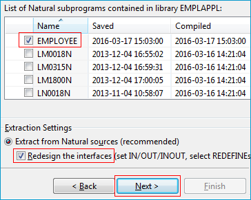
Model the extracted interface to suit your needs by creating a function getListOfEmployees.
Mark the parameter OPERATION in the Natural Subprogram Source view or the Natural Parameters pane
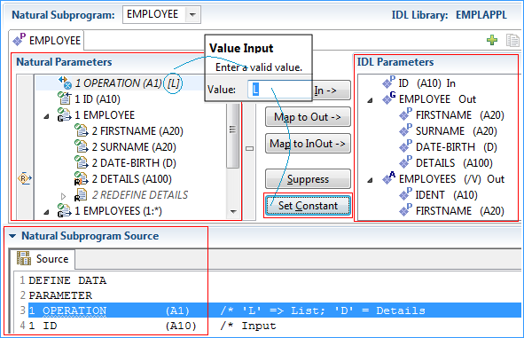
Set Constant 'L' for the parameter OPERATION.
In the Natural Parameters pane, constant [L] is shown in brackets after the Natural parameter.
OPERATION is removed from the IDL Parameters pane.
At runtime, EntireX passes L as the value for the OPERATION parameter.
This forces the EMPLOYEE LIST function to be executed.
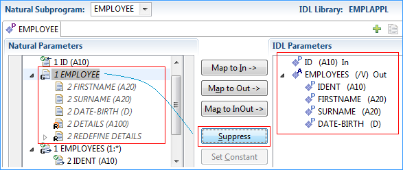
Suppress the Natural group EMPLOYEE, which is unused in the LIST function.
This removes the IDL group EMPLOYEE from the IDL Parameters pane.
The Natural parameter EMPLOYEE remains.
Parameters that are suppressed in the IDL Parameters pane are displayed in italic font in the Natural Parameters pane.
Note:
Parameters set to constant are also displayed in italic font, because Set Constant suppresses them in the IDL Parameters pane too (see Step 2).
Also suppress Natural parameter ID, similar as already done for Natural group EMPLOYEE in the previous step.
Specify a readable name getListOfEmployees for the IDL Parameters,
using the toolbar button ![]() .
The new name appears on the tab.
.
The new name appears on the tab.

Create a getDetailsOfEmployees function for the DETAILS operation.
A new interface is needed for this. Use the toolbar button ![]() and open a new tab.
The IDL parameters are reset to defaults. The previously extracted
and open a new tab.
The IDL parameters are reset to defaults. The previously extracted getListOfEmployees interface still exists in the first tab.
Once you reactivate the first tab, you will see the interface of getListOfEmployees again.

Specify a readable name getDetailsOfEmployee for the IDL Parameters,
using the toolbar button ![]() . The name is displayed on the tab.
. The name is displayed on the tab.

Set constant 'D' for Natural parameter OPERATION to execute the EMPLOYEE DETAILS operation at runtime.
The IDL parameter OPERATION is removed from the IDL Parameters pane
and displayed in the Natural Parameters pane. The italic font indicates suppression.

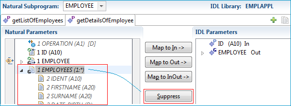
Suppress the Natural X-array EMPLOYEES, which is not needed in the DETAILS interface.
The IDL parameter EMPLOYEES is removed from the IDL Parameters pane and displayed in italic font
in the Natural Parameters pane.
By default, the Natural parameter DETAILS is mapped. In this case, the redefinition of DETAILS
in the Natural Subprogram Source pane contains information of more value.
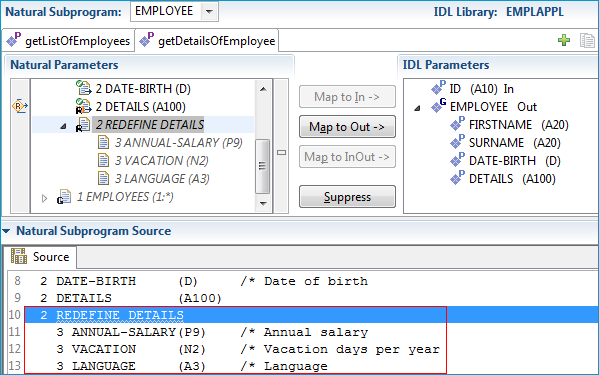
You can map the redefinition of DETAILS in the Natural Subprogram pane if you prefer to use this rather than the DETAILS parameter.
Select REDEFINE DETAILS in the Natural Subprogram pane and press .
The IDL parameter DETAILS is turned into a group containing parameters that match the Natural redefinition.
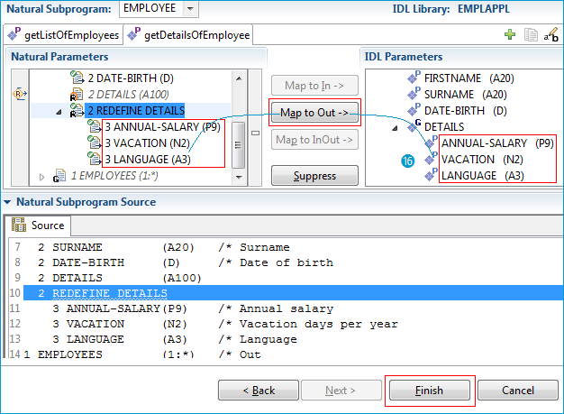
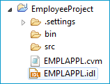
Press to retrieve the extraction result in the form of a Software AG IDL file. At the same time, a Server Mapping Files for Natural (Designer file with extension .cvm) is created. The Software AG IDL File describes the interfaces from the , while the server mapping file contains the mapping to the real Natural server. Both of these files must be kept together and in sync, otherwise a call to the Natural server may fail.
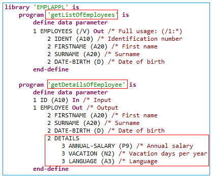
To summarize: We created two IDL interfaces. In the IDL file, these resulted in two IDL programs:
getListOfEmployees and getDetailsOfEmployee.
Both IDL programs were given readable names (Steps 4 and 6). Meaningful fields were kept,
while superfluous fields were suppressed (Steps 3 and 8).
The program getDetailsOfEmployee contains the redefined fields of parameter DETAILS (see below) mapped during extraction (step 9).
Note:
During runtime the RPC client generated with the extracted interface will send data for the redesigned interfaces,
while your Natural server still expects EMPLOYEE data. The EntireX runtime transforms the incoming data stream from the RPC client, using the server mapping file.
The following table highlights the differences when shaping an interface with a user-defined mapping compared with a fast-path extraction.
| Interface Shaping with User-defined Mapping | Fast-path Extraction | |
|---|---|---|
| General | User-defined interface with dedicated mapping. For our example, the interfaces are small and tidy and more self-explanatory
with long, readable interface names. They are easier to use with the hidden OPERATION field and the suppressed Natural fields, which are not needed.
|
Automatic, quick result extraction with Natural-like interfaces on IS. For our example, the IS interface EMPLOYEE matches exactly 1:1, field by field.
|
| IS service(s) | Multiple small and handy IS services; each OPERATION code is mapped to a separate IS service.
|
One big IS service. |
| IS service name | Readable long name. | Short Subprogram name; up to 8 characters. |
| IS fields | Usage of and reduces the message length. This keeps focus on relevant data itmes and keeps the client's interface clean. It may also improve performance. | The IS fields and Natural server subprogram parameters match 1:1. As Natural layout descriptions are sometimes used for many different purposes, irrelevant data items appear and clutter up the IS interface. |
OPERATIONparameter
|
Suppressed: the OPERATION parameter does not exist in the IS service as an IS field.
|
The OPERATION parameter exists in the IS service as an IS field and needs to be filled in by the client endpoint.
|
OPERATION code
|
The OPERATION code is provided internally by EntireX runtime in the OPERATION field.
|
The OPERATION code needs to be specified in the IS service in the OPERATION field by the client endpoint.
|
REDEFINE parameters
|
Either the parameter that is redefined or one of its redefinitions is available as an IS field. | Only the parameter that is redefined is available as an IS field. Redefinitions of the parameter are not available as IS fields. |
A user-defined mapping enables you also to define alternative mappings for Natural paraneters (REDEFINEs, etc.).
These enable scenarios with Natural servers where data exchange is not fully described by the PDA of the Natural subprogram.
For more information refer to the User-defined Mapping under Natural to IDL Mapping in the IDL Extractor for Natural documentation.
The following pictures use the extraction results described under Extracting a Natural Server - Modern Method with User-defined Mapping.
 To test the extraction results (optional)
You can test the results of the extraction operation and the REST server back end, using the EntireX IDL Tester. From the context menu of the IDL file in the Designer, choose .
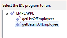
Select getDetailsOfEmployee.
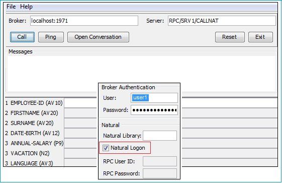
Note that the broker and server parameters contain the explicit route to call the server program, and you can optionally ping the connection from this client. With the > dialog, check Natural Logon. If required set:
User and Password for broker authentication
RPC User ID and RPC Password for server authentication
See EntireX IDL Tester in the Designer documentation.
Check the Integration Server log, the EntireX Adapter log or the RPC logs. Applies to all connection methods.
This section describes your first steps to create a new Integration Server connection. This is described in more detail under Using the Integration Server Wrapper, for example working with existing Integration Server connections. This section covers the following topics:
 To start the Integration Server Wrapper wizard
In the context menu of a Software AG IDL file, choose .
This starts the wizard with a list of existing Integration Server Wrapper connections.
Note:
If the selected IDL file is not valid because of a syntax error,
an error dialog comes up and the wizard does not start.
Continue with Step 2: Create a New Integration Server Connection.
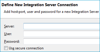
 To create a new Integration Server connection
Define the new Integration Server connection on the wizard page.
Notes:
Choose and continue with Step 3: Select the Connection Type.
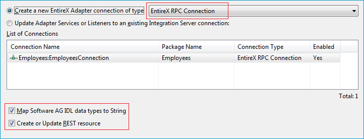
 To create a new connection
Select a connection type from the drop down list. Connection types are described under EntireX Adapter Connections in the EntireX Adapter documentation and Introduction to the Integration Server Wrapper.
Note:
The list of connection types is filtered: connection types that require a license are only shown if a corresponding license
file is available.
Reliable RPC connections are only shown if all IDL programs contain only IN parameters.
Also, if a server mapping file is available, only those connection types that support the interface type specified in the
server mapping file are shown.
Click and continue with Step 4: Define Adapter Services for an RPC Connection.
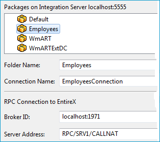
 To create a connection and related adapter services
Select a package for the created objects.
Define a folder name. If the folder does not exist, it will be created.
Define a connection name.
Define the parameters of the connection type. For details, see the EntireX and your webMethods Integration Server Applications.
As a result, the folder will contain the connection and the adapter services (one for each IDL program). The name of a service is the same as the respective IDL program.
The default settings for the adapter services are:
the Default package; if not available, the first package
the IDL library name for the Folder Name
the IDL library name with the suffix "Connection" for the Connection Name
Note:
When creating a connection, a package dependency is added such
that the selected package depends on webMethods EntireX
(the package WmEntireX) with the version currently used.
 To create or update a REST resource
Make sure checkbox Create or Update REST resource is checked.
Select a package.
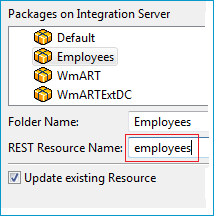
Define a folder name. If the folder does not exist, it will be created.
Define the REST Resource name.
Check Update existing Resource if you want to add additional services to an existing resource.
 To edit the REST resource
Switch to the Service Development perspective of Software AG Designer.
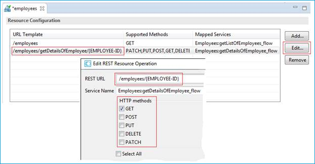
Refresh the package where you generated the REST Resource in the previous step.
Open the REST Resource.
Edit the REST URLs and HTTP Methods to match the functionality of your application.
For more information see:
REST Developer's Guide in the webMethods Integration Server documentation for information on using the generated REST resources
Configuring a REST Resource Using the URL Template-Based Approach in the online help provided under Software AG Designer Guides > webMethods Service Development Help > Working with REST
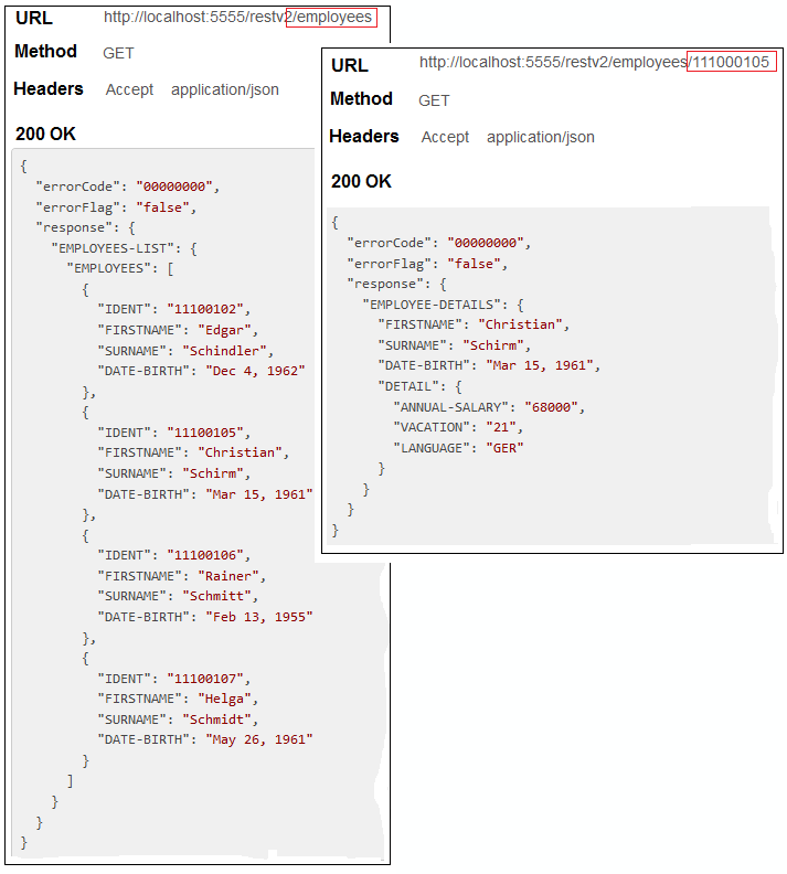
Use an appropriate REST client, specify URL, Method and Headers and invoke your REST resource:
