This document covers the following topics:
The INPUT statement offers the possibility to use
predefined map layouts.
When you create or open a map, the map editor is invoked. The map editor is a multi-page editor which provides the following pages:
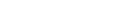
Layout
Shows the graphical representation of the map and provides a
palette for inserting controls into the map.
List
Displays the Natural code corresponding to the current state
of the entire map.
Data
Displays the data definition for the data area that is
currently selected in the Outline view.
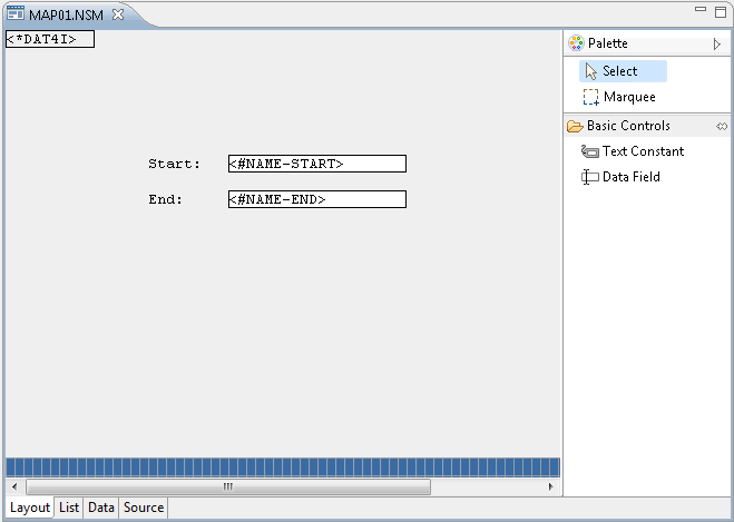
Source
Only shown when at least one processing rule has been defined.
Shows the code for a processing rule.
The behavior of the map editor can be influenced by changing the Natural preferences. See Map Editor in Setting the Preferences.
For further information on maps, see the Programming Guide in the Natural documentation for the appropriate platform.
The map editor uses the following views of the NaturalONE perspective:
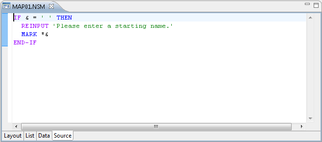
This view shows the various components of the map in a tree. This includes data definitions, field definitions and processing rules (map-based and field-based). If a dynamic layout is present, its components are also shown in a separate hierarchy.
You can invoke a context menu, for example, to delete the selected item or to create a new processing rule.
You can navigate to a particular item in the map by selecting it in the Outline view, and vice versa.
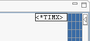
When the definition for an element in the tree has been modified or when a new element is created, a label decoration in the form of an asterisk is shown for this element.
Note:
The label decorations for modifications in the map editor are
controlled by the preferences under General > Appearance >
Label Decorations. If you do not want to have these label
decorations, just go to the above mentioned preference page and deselect
Natural Map Editor Modifications.
Errors and warnings are also displayed in the form of label decorations. See Error Handling in the Map Editor for further information.
This view shows the dependencies between the map which is currently shown in the active editor window and other objects. For example, when the passive cross-references are currently displayed, you can see all Natural objects that reference the map being edited.
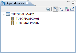
For further information on this view, see Dependencies View in the description of the source editor.
This view shows the properties of the item that is currently selected in the active map editor window or in the Outline view. You can change the values shown in this view. Example for a data field:
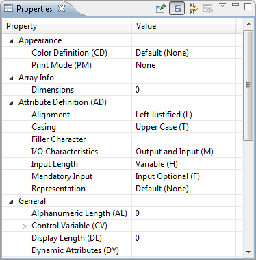
Further information on the different types of properties is provided below.
You can add controls using the palette, by cloning existing controls, or by importing data definitions.
 To add a control to the map
Make sure that the Layout page is shown.
If the palette is currently hidden, display it using its arrow button.
Note:
By default, the palette is shown on the right side of the
map editor. You can also move it to the other side of the map editor.
Click the graphical representation of the required control in the palette.
Click the position in the map where you want to place the control. Do not release the mouse button immediately. Keep it pressed and draw the outline of the control until it has the required size. Then release the mouse button.
The new control is now shown in the Outline view and in the Properties view.
To clone a control
Select one or more controls in the Layout page. These can be text constants or data fields.
Press CTRL and drag the selected control(s) to a different position in the map.
Or:
Use copy and paste. This also works between two different
maps. When controls are pasted into the same map, they overlay the positions of
the copied controls and you have to move them to the desired positions.
To create a control based on an external data definition
(method 1)
Make sure that the Layout page is shown.
Invoke the context menu at the position where you want to place the imported data field(s) and choose .
Or:
Press ALT+SHIFT+I.
The Import Data Fields dialog appears.
From the dialog, select the data definition(s) to be imported as described in Importing Data Fields.
When the selected field already exists on the map as a modifiable field and can be adapted, a message confirmation dialog appears. This behavior can be influenced by changing the Natural preferences. See Map Editor in Setting the Preferences.
The warning does not appear when the field exists as an Output Only field on the map. In this case, the field is imported as a new field at the selected position. To adapt the data definition, perform the following steps before importing the data field:
Select the I/O characteristics in the Properties View.
Change the setting from Output Only to another attribute value.
Switch the I/O characteristics back to the old setting.
To create a control based on an external data definition
(method 2)
Switch to the Data page.
Invoke the context menu at the position where you want to place the imported data field(s) and choose .
Or:
Press ALT+SHIFT+I.
The Import Data Fields dialog appears.
From the dialog, select the data definition(s) to be imported as described in Importing Data Fields.
For each imported data definition, a new field node is created for the current data section in the Outline view.
Move the data definitions to data fields as described in Moving Data Definitions to Data Fields.
You can either select controls in the Layout page or in the Outline view.
The palette that is provided on the Layout page offers different tools for selection purposes: the select tool (default) and the marquee tool.
To select controls using the select tool
Make sure that Select is selected in the palette.
In the Layout page, click the control that you want to select.
Or:
To select more than one control, hold down CTRL
and then click each required control in the Layout
page.
The selection is automatically reflected in the Outline view.
To select controls using the marquee tool
Select Marquee in the palette.
In the Layout page, drag the mouse around all controls that you want to include in your selection.
The selection is automatically reflected in the Outline view.
To select several controls in the Outline
view
Hold down CTRL and then click each required control in the Outline view.
The selection is automatically reflected in the Layout page.
To select a whole array
Press ALT.
In the Layout page, click any one of the array's field elements.
Note:
To perform a clipboard operation
(, ,
) on an array, it is sufficient to select one
or more of its elements. By default, a message dialog appears, prompting you to
confirm the operation. You can suppress this message dialog for the future,
either within the message dialog itself or in the Natural preferences (see
Map
Editor in Setting the Preferences).
This feature allows clipboard operations to work in conjunction with marquee
selection (see above).
Although multiple controls can be selected, only one of these controls at any time is the reference control, and is distinguishable from the other selected controls by having solid drag handles instead of hollow ones. For some operations such as control deletion, the reference control is irrelevant. However, for other operations such as field alignment, one of the selected controls must be taken as the basis for the operation, and this is invariably the reference control.
To change the reference control
In the Layout page, select all required controls.
Press and hold down SHIFT.
Click the new reference control.
Perform the desired action.
To resize or move a control
Select the control in the Layout page of the map.
Use the mouse to resize or move the control.
Or:
Modify the corresponding values in the
Properties view.
Note:
Resizing an array causes the number of array elements to
be changed in preference to the width or height of each element. Since only
whole rows and columns can be displayed, this may result in nothing appearing
to happen if the bounding rectangle for the array was not expanded enough in
either direction to accommodate an additional row or column. See also
Selecting Controls in
the Map for information on how to select a whole array
prior to resizing it.
To rename a text constant
Select the text constant in the Layout page of the map or in the Outline view.
Modify the Label value in the Properties view.
Or:
In the Layout page, click the text
constant once more and then type the new label.
To delete a control
Select the control in the Layout page of the map or in the Outline view.
Press DEL.
Or:
In the Outline view, invoke the context
menu and choose .
To align several controls
Select the controls in the Layout page of the map.
Invoke the context menu and choose .
The controls are aligned relative to the reference control. See also Changing the Reference Control for Selection
You can define processing rules and Predict free rules for data fields. See also Changing the Properties for a Rule.
To create a processing rule
Select a data field in the Outline view.
Or:
Select the top-level node in the
Outline view if you want to create a processing rule for
the entire map.
Invoke the context menu and choose .
Or:
Press CTRL+ALT+R.
A new rule is shown in the Outline view and the Source page of the map editor is automatically opened.
Enter the processing rule on the Source page. For example:
IF & = ' ' THEN
  REINPUT 'Please enter a starting name.'
  MARK *&
END-IF
An ampersand (&) in the processing rule will dynamically be replaced with the name of the field.
Define the rank for the rule in the Properties view.
The rank defines the sequence in which the rules for the different fields are to be processed.
To link Predict free rules
Only available when Predict is available in the corresponding Natural server environment.
Select a data field in the Outline view.
Invoke the context menu and choose .
The following dialog box appears.
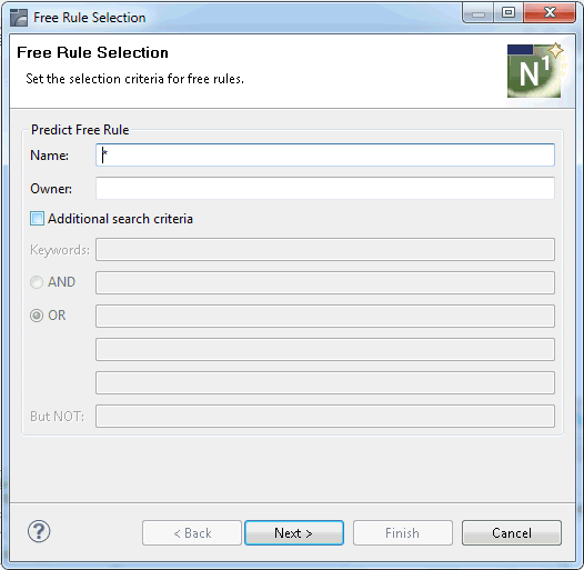
Enter the rule name, the Predict owner and up to five keywords under which the rule is stored in Predict.
Asterisk notation can be used for the rule name, the
keywords can be combined with the Boolean operators AND and
OR, and a BUT NOT keyword can also be specified.
Choose the button.
A list of free rules is shown.
Select the rule(s) you want to link to the field.
Optional. Choose the button to display a preview of the selected rule(s).
Choose the button to link the rule(s) to the field.
To unlink Predict free rules
Select the rule in the Outline view.
Press DEL.
Or:
Invoke the context menu and choose
Delete.
Notes:
You can move a data definition from a local data area or parameter data area which is defined for the map to a data field.
To move a data definition to a data field
Select a data definition in the Outline view (that is, select an entry under Local Data or Parameter Data).
Invoke the context menu and choose .
The data definition is removed under Local Data or Parameter Data.
A new data field is now available on the Layout page. It is initially positioned in the upper left corner of the map (row 1 and column 1) from where you can move it to the required position.
When you invoke the context menu on the List, Data or Source page of the map editor, several standard source editor commands are also available. For detailed information on these commands, see the corresponding descriptions in Using the Source Editor.
When you display the properties for the map itself (for example, by selecting the top-level entry in the Outline view), you can change the following information:
| Property | Description |
|---|---|
| Appearance | |
| Control Variable |
The name of an attribute control variable, the content
of which determines the attribute characteristics of fields and texts that have
the attribute definition Removing an attribute control variable from the map properties implies that the attribute control variable is removed from the map, too, unless it is associated to any other map field. |
| Print Mode (PM) |
The default print mode for variables. This value is copied into the field definition when a new field is created. You can select the required value from the drop-down list box:
None None means that the standard character set is used. For further information, see the description of the
session parameter |
| Filler Characters | |
| Label Filler |
Trailing filler character used for padding text constant labels if the length of the label is less than the width of the text constant. |
| Optional, complete |
Filler character used for fields that are optional but must be completely filled if used. |
| Optional, partial |
Filler character used for fields that are optional and can be partially filled. |
| Required, complete |
Filler character used for fields that are required and must be completely filled. |
| Required, partial |
Filler character used for fields that are required and can be partially filled. |
| General | |
| Auto Rule Rank |
The default rank for any newly created processing rule in the map. (Later on, you can alter ranks individually). |
| Column Shift |
Column shift (0 or 1) to be applied to the map. This feature can be used to address all 80 columns on a 80-column screen (column shift = 1, line size = 80). |
| Decimal Character |
The character to be used as the decimal notation character; the default character is a period (.). |
| Field Sensitive |
When set to true, the consistency check for a map field is made as soon as the field is filled by the user. When set to false, field checking is performed when the map is filled completely. |
| Help Map |
When set to true, the map is marked as help text. When set to false, the map is not marked as help text. |
| Manual Skip |
When set to true, the cursor is not moved automatically to the next field in the map at execution time, even if the current field is completely filled. When set to false, the cursor is moved automatically to the next field in the map at execution time. |
| Output Map |
When set to true, the result of the map definition
process is a When set to false, the result of the map definition
process is an |
| Right Justified |
When set to true, numeric and alphanumeric fields copied from data definitions in other Natural objects are right-justified. When set to false, numeric and alphanumeric fields copied from data definitions in other Natural objects are not right justified. |
| Standard Keys |
When set to true, the last two lines of the map remain empty so that function key specifications can be entered at execution time. When set to false, all lines are used for the map. |
| Upper Case |
When set to true, input is converted to upper case during map execution. When set to false, input is not converted to upper case during map execution. |
| Zero Printing |
When set to true, numeric fields that contain all zeroes (print one zero, right-justified) are printed. When set to false, the printing of numeric fields that contain all zeroes is suppressed. |
| Help | |
| Helproutine Name |
The name of the helproutine or help map that is called at execution time when the help function is invoked for this map (global help for the map). |
| Help Field Default |
Only shown when the name of a helproutine or help map has been defined. When set to true, the helproutine or help map specified for the map applies as the default to each individual field on the map, that is, the name of each field is passed individually to the helproutine or help map. When set to false, the name of the map is passed to the helproutine or help map. |
| Help Parameters |
Only shown when the name of a helproutine or help map has been defined. Enter the name of the parameter(s) that will be called at execution time when the help function is invoked. |
|
The syntax that applies to specifying helproutine names
and parameters corresponds to the syntax of the session parameter
|
|
| Layout | |
| Layout Name |
The name of the map that serves as standard layout for the current map. You can use this property to simplify the creation of many similar maps by creating one map as the basic layout map with a set of fields to be used by the other fields. In all similar maps, you specify the name of the standard layout map and you only add the fields that are specific to the new map. |
| Dynamic Layout |
When set to true, the fields are imported dynamically into the layout at runtime. This means that you can alter your standard layout and this change will automatically be reflected in all similar maps using this layout. When set to false, the standard layout is not used dynamically. |
| RTL Support | |
| Visual Order |
When set to true, the text constants of the map are assumed to be in visual order. When set to false (default), the text constants are assumed to be in logical order. See also Bidirectional Language Support. |
| Size | |
| Columns |
The number of columns which make up the width of the map. |
| Rows |
The number of rows which make up the height of the map. |
When you select a text constant, you can change the following properties:
| Property | Description |
|---|---|
| Appearance | |
| Color Definition (CD) |
Defines the color attribute for the text constant. You can select the required value from the drop-down list box:
Default (None) For further information, see the description of the
session parameter |
| Attribute Definition (AD) | |
| Representation |
Defines how the value is displayed. You can select the required value from the drop-down list box:
Default (None) For further information, see the description of the
session parameter |
| General | |
| Label |
The label that is to appear on the map. |
| Position | |
| Column |
The column in the map in which the text constant starts. When you move the text constant using the mouse, this value is automatically adjusted. |
| Row |
The row in the map which contains the text constant. When you move the text constant using the mouse, this value is automatically adjusted. |
| Size | |
| Width |
The length of the text constant. When you resize the text constant using the mouse, this value is automatically adjusted. |
When you select a data field, you can change the following properties:
| Property | Description |
|---|---|
| Appearance | |
| Color Definition (CD) |
Defines the color attribute for the data field. You can select the required value from the drop-down list box:
Default (None) For further information, see the description of the
session parameter |
| Print Mode (PM) |
Defines the print mode for the data field. You can select the required value from the drop-down list box:
None None means that the standard character set is used. For further information, see the description of the
session parameter |
| Array Info | |
| Dimensions |
You can define an array of up to three dimensions. For further information, see Defining Arrays. |
| Attribute Definition (AD) | |
| Alignment |
Defines how the content of the field is displayed. You can select the required value from the drop-down list box:
None None means that the default alignment is used which depends on the format of a field. Left-justified is the default for alphanumeric fields. Right-justified is the default for numeric fields. Leading zeros can be defined for numeric values which are then displayed right-justified. |
| Casing |
Defines whether the Casing setting is inherited by the Natural session (default), values are translated to upper case, or lower case values are accepted. You can select the required value from the drop-down list box:
Default (None) |
| Filler Character |
You can specify a character that is to be used to fill empty input fields or modifiable output fields. When you edit an input field, which is padded with blanks to its maximum length, it may appear as if the text cannot be edited. In such cases, the blanks must be explicitly deleted from the end of the field. |
| I/O Characteristics |
Defines whether the field is an input field or output field. You can select the required value from the drop-down list box:
Input Only (A) |
| Input Length |
Defines whether the value entered in the field must have same length as the field (fixed length - only relevant for input-only fields) or whether the value entered in the field can be shorter than the field (variable length). You can select the required value from the drop-down list box:
Fixed (G) |
| Mandatory Input |
Defines whether a value must be entered in the field
(only relevant for input-only fields (
Input Mandatory (E) |
| Representation |
Defines how the value is displayed. You can select the required value from the drop-down list box:
Default (None) |
|
For further information, see the description of the
session parameter |
|
| General | |
| Alphanumeric Length (AL) |
Only shown for Natural data formats A (alphanumeric) and U (Unicode). You can specify the default output length for an alphanumeric field; that is, when it is specified shorter than the field length, the field will be right-truncated. For further information, see the description of the
session parameter |
| Control Variable (CV) |
You can enter a dynamic field attribute control variable. This is the control variable that will contain the attributes to be used for the data field. The variable must be defined with Natural data format C (for attribute control) in the program that references the map. The control variable also contains a
For further information, see the description of the
session parameter |
| Display Length (DL) |
Only shown for Natural data formats A (alphanumeric) and U (Unicode). This property can be used to specify the output length for Unicode strings which can require extra space. For further information, see the description of the
session parameter |
| Date Format (DF) |
Only shown for Natural data format D (date). This property determines the length of a date when converted to alphanumeric representation without an edit mask being specified. You can select the required option from the drop-down list box:
Default (none) For further information, see the description of the
session parameter |
| Dynamic Attributes (DY) |
You can assign attributes for dynamic attribute field display. For further information, see the description of the
session parameter |
| Edit Mask (EM) |
You can enter the edit mask to be used for the data field. For further information, see the description of the
session parameters Note: |
| Float Length (FL) |
Only shown for Natural data format F (floating point). You can specify the mantissa length of a floating point variable during input or output. For further information, see the description of the
session parameter |
| Format |
You can select the required Natural data format from the drop-down list box:
Alphanumeric (A) The default format is A. Note: |
| Length |
Only shown for Natural data formats A (alphanumeric), B (binary), F (floating point), I (integer), N (numeric), P (packed numeric) and U (Unicode). You can specify the internal length of the field which is used by a program that references this field. For valid input values, see Format and Length of User-Defined Variables in the Programming Guide in the Natural documentation for the appropriate platform. |
| Name |
The name of the field. Note: |
| Numeric Length (NL) |
Only shown for Natural data formats B (binary), I (integer), N (numeric) and P (packed numeric). You can specify the default input/output length for a
numeric field used in a For further information, see the description of the
session parameter |
| Sign Position (SG) |
Only shown for Natural data formats F (floating point), I (integer), N (numeric) and P (packed numeric). Using the drop-down list box, you can specify whether a sign position is to be allowed for the field. For further information, see the description of the
session parameter |
| Zero Printing (ZP) |
Only shown for Natural data formats F (floating point), I (integer), N (numeric) and P (packed numeric). If set to on, zero values are printed as one zero. If set to off, zero values are suppressed. For further information, see the description of the
session parameter |
| Help | |
| Helproutine Name |
You can enter the name of a helproutine or help map to be assigned to the map field. The helproutine or help map is then invoked for the map field at execution time when a help request is made for this map field. |
| Help Parameters |
Only shown when the name of a helproutine or help map has been defined. Enter the name of the parameter(s) that are to be passed to the helproutine or help map Removing a parameter from this text box implies that the parameter is also removed from the map, unless the parameter is a map field or is associated with any other map field as a help parameter or is a start index for an array. |
|
The syntax that applies to specifying helproutine names
and parameters corresponds to the syntax of the session parameter
In addition to the syntax explanations provided for
operand1:
operand2:
|
|
| Position | |
| Column |
The column in the map in which the field starts. When you move the field using the mouse, this value is automatically adjusted. |
| Row |
The row in the map which contains the field. When you move the field using the mouse, this value is automatically adjusted. |
| Size | |
| Width |
The length of the field. When you resize the field using the mouse, this value is automatically adjusted. |
|
The following attributes determine the width of a field in the following priority sequence: DL > EM > { AL, NL, FL } > [SG] Length
When the width property is changed, the highest priority attribute that is used (i.e., which is non-zero or non-blank) is adjusted. Exception: The edit mask (EM) and length attributes are not automatically adjusted. Examples:
Given field length = 30
|
|
When you select a rule, you can change the following properties:
| Property | Description |
|---|---|
| Type |
Rule type. Can be one of the following values:
A free rule can be converted into an inline rule by selecting the type Inline Rule from the drop-down list box. For all other rule types, this drop-down list box is not available. Note: |
| Rank |
A numeric value (0 - 99) that determines the order in which the rule is executed relative to the others (if any). A field can have up to 100 processing rules, each of which must have a unique rank. At map execution time, the processing rules are executed in ascending order, first by rank, then by screen position of the field. For this purpose, processing rules associated with the map itself are always assumed to have the first screen position. The default rank for automatic rules is defined by the property Auto Rule Rank in the map properties. See also Changing the Properties for the Map. |
Arrays are defined in the properties of a data field. You can define an array of up to three dimensions. The order in which the dimensions of the array are mapped to the map layout is determined by the values you enter.
The number of the shown array-specific properties depends on the dimension that you specify. When you specify, for example, the value 3 in the Dimensions property, the following properties are shown:
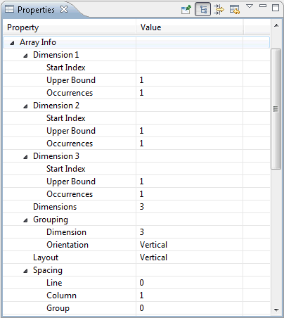
You can change the following array properties:
| Property | Description |
|---|---|
| Dimensions |
When set to 0, dimensions are not used (default) and this is the only property that is shown under Array Info. You can set the value to 1, 2 or 3 to use a one-, two- or three-dimensional array. In this case, additional properties are shown (see below). |
| Layout |
Determines how the array is represented in the map layout (vertically or horizontally). |
| Dimension n | |
| Start Index |
The starting index value for each dimension. You can enter a number or the name of a variable; the actual value is supplied in the program that invokes the map definition. Unless defined otherwise as a field in the map, the variable is assumed to be defined as Natural data format/length N7. Removing a starting index value from an array implies that the variable is removed from the map, too, unless it is a map field or it is associated to any other map field as a starting index value or help parameter. |
| Upper Bound |
The upper bounds of the field. This number is the highest occurrence of the first, second and third dimension. |
| Occurrences |
The number of occurrences that are to be displayed on the map. You can also use the mouse to resize the field vertically; the appropriate value is automatically considered in the properties. This does not apply to the third dimension of a three-dimensional array because only two ranges of occurrences can be displayed on the screen. One-dimensional arrays can be displayed as multi-line/multi-column fields. For these arrays, the second number of occurrences and the layout for the second dimension can be defined. |
| Spacing | |
| Line |
Only shown for arrays that have a dimension with a vertical orientation. This is the number of blank lines to be inserted horizontally between each dimension occurrence in the array. |
| Column |
Only shown for arrays that have a dimension with a horizontal orientation. The number of blank columns to be inserted vertically between each dimension occurrence in the array. |
| Group |
Only shown for arrays with a grouped dimension. The number of blank lines to be inserted vertically or columns to be inserted horizontally between each occurrence of the grouped dimension. |
| Grouping | |
| Dimension |
Only shown for a two- or three-dimensional array. The index of the dimension for which the array elements are grouped within the other dimension with the same orientation. |
| Orientation |
Only shown for a three-dimensional array. The orientation in which the elements corresponding to the grouped dimension are shown. |
For further information on arrays, see the Programming Guide in the Natural documentation for the appropriate platform.
The following properties are available for the map itself and for all controls in the map:
| Property | Description |
|---|---|
| Modified |
Modification status (read-only). When set to true, the selected item has been modified since the last time the map was saved. |
| Error Status |
Error and warning status (read-only). Can be one of the following values:
Errors and warnings are displayed in the form of label decorations in the Outline view. For information on the severity of an error or warning, see Error Handling in the Map Editor. |
Maps are saved using the standard Eclipse functionality.
However, when a dynamic layout is present, the following applies. When you save a map, only the so-called host map is saved. The layout map is only saved when you close the editor; in this case, a dialog appears asking whether you want to save the layout map.
If you want to save the layout map at an earlier point in time, proceed as described below.
To save the layout map (dynamic layout only)
In the Outline View, select the layout map.
Invoke the context menu for the map and choose .
Or:
Press CTRL+S.
Or:
From the menu, choose
.
When you have opened a map from the Natural Server view, you can stow the map directly from within the map editor.
To stow the map (Natural Server view
only)
Make sure that the Layout page is shown.
Invoke the context menu for the map and choose .
Or:
Press CTRL+T.
When you save a map, the following consistency checks are automatically performed in order to determine the validity of the map:
| Consistency Check | Description |
|---|---|
| Critical Errors | Detects whether the map contains one or
more critical errors, indicating that the map could not be loaded successfully.
If so, an error message is displayed. This condition is usually caused by
syntax errors within the DEFINE DATA or
INPUT/WRITE statements, which can be inspected by
opening the map with the source editor.
|
| Invalid Data Definitions | Detects whether one or more of the data sections in the map contain errors. If so, an error message is displayed. This condition is usually caused by one or more of the entered data definitions having a syntax error. |
| Empty Map | Checks whether the map contains no
fields. If so, a warning message is displayed. Note that empty maps are not
syntactically valid in Natural, because the underlying INPUT or
WRITE statements require at least one operand to be present. In
addition, maps containing one or more processing rules but no fields cannot be
opened correctly due to this restriction. To minimize the risk of this
situation arising, the saving of such maps is not allowed.
|
| Overlapping Fields | Detects whether the map contains one or more overlapping fields (thus making it syntactically invalid). If so, an error message is displayed. In addition, the overlapping fields are automatically selected in order to assist you in locating the source of the error. |
If you want to validate the map at an earlier point in time, proceed as described below.
To validate the map
Make sure that the Layout page is shown.
Invoke the context menu for the map and choose .
Or:
Press CTRL+ALT+V.
In the case of an error, a message dialog appears providing information about the error.
By default, a message dialog is shown even if the validation was successful. This behavior can be changed in the Natural preferences. See Map Editor in Setting the Preferences.
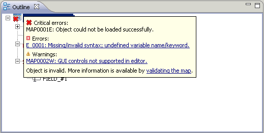
In the Outline view, errors and warnings are displayed in the form of label decorations (see also Viewing the Status Properties). The image used depends on the severity as follows:
| Image | Description |
|---|---|
| Critical error. This decoration is displayed for the top-level node if one or more components of the map (such as field or data definitions) could not be loaded correctly, typically due to a syntax error. Critical errors cannot be corrected within the current editor session. The exact location of the error(s) can be determined by opening the map using the source editor. | |
| Error. This decoration is displayed to represent errors that are fixable in the current editor session. | |
| Warning. This decoration alerts the user to conflicts that are not clearly serious enough to be regarded as errors. |
When you move the mouse over an item in the Outline view which causes an error or warning, a tooltip appears. This tooltip may contain one or more links. You can navigate to an error in a map by clicking the corresponding link. In specific cases, a link is also available which allows you to validate the map and thus display information about the error in a message box (see also Validating Maps).
You can also navigate to an error in a map using the Problems view (see the description under Problems in Your Natural Sources). The preferences for the source editor, especially the Show error list option, also apply to the List, Data and Source pages of the map editor.
When you navigate to an error, the map editor responds to such a request by trying to find the first map component (data definition, text constant, data field, array element or processing rule) that contains (or partially contains) the line represented by the chosen error marker, and (if such a component is found) selects it on the List page of the map editor, or in the case of a processing rule, selects it on the Source page. If no component is found, or the navigation fails for any other reason, a message dialog is displayed.
It is important to recognize that the errors shown in the Outline view tooltip relate to the current state of the map within the editor, whereas the resource markers shown in the Problems view relate to the map as stored in the workspace.
Information relating to the error or warning may also be written to the Error Log view.
Notes: