This section describes how to use the Natural Construct client generation wizards to generate Natural modules, as well as how to define user exits for additional processing that is preserved during regeneration. The following topics are covered:
Note:
The following description refers to the generation of a new
Construct model on the NaturalONE client based on Construct installed on the
Natural server.
 To access the client generation wizards
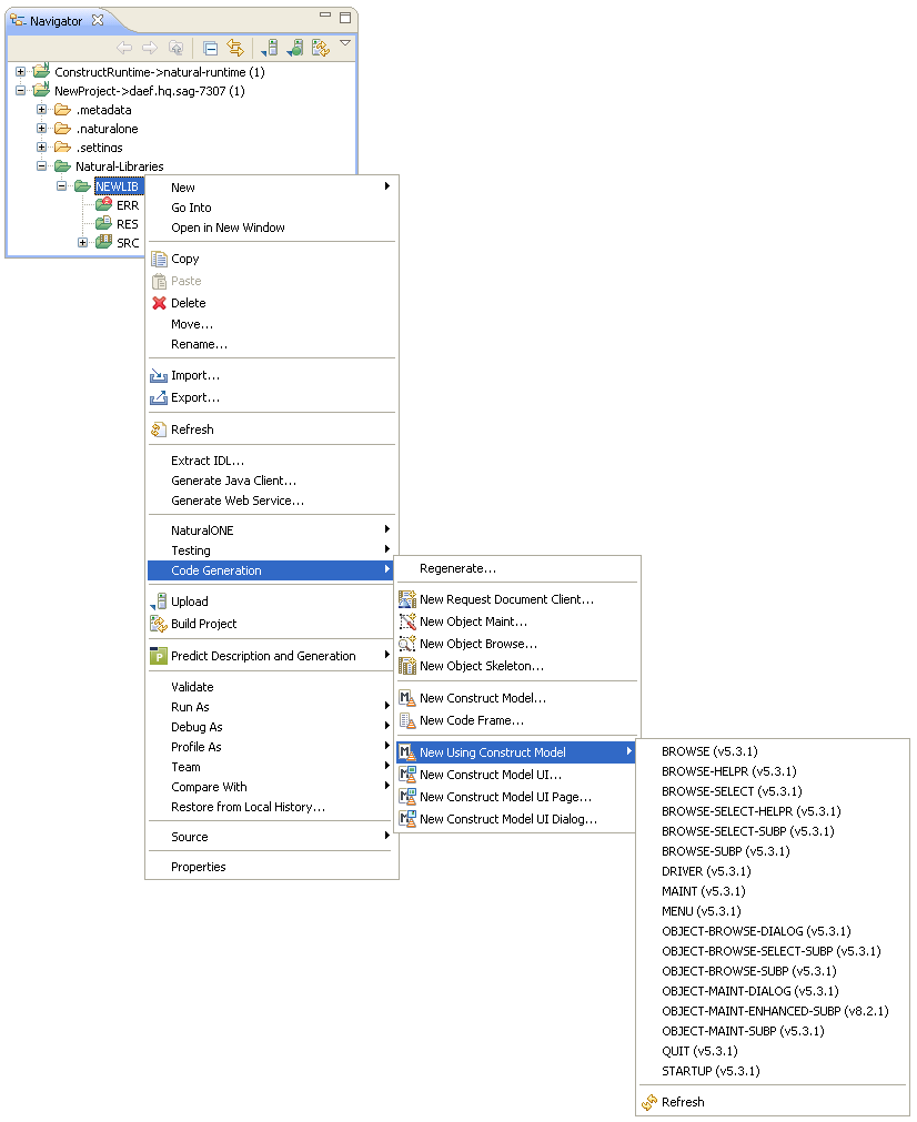
Open the context menu in the Navigator view for the NaturalONE project in which you want to generate the modules.
Or:
Open the context menu in the Navigator
view for the library in which you want to generate the modules.
Note:
You can also access the wizards using standard NaturalONE
functionality (i.e., through the File menu or using the
toolbar option.
Select .
A list of the supplied client generation wizards is displayed. For example:
Note:
The list of wizards displayed in this menu is based on
which Construct version is installed on the target server. For example,
Construct V8.2 wizards will not be available if the project is attached to a
Construct V5.3 server.
Select the wizard you want to use.
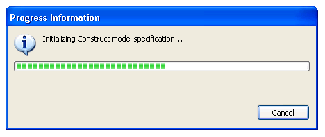
The Progress Information window is displayed, indicating progress as the model specification PDA is initialized by the model's clear subprogram on the server to set the model defaults (the same process initiated when you enter "NCSTG" from a character-based Natural connection). For example:
The clear subprogram will only be called when all the following conditions are true:
The selected target project is valid and connected to a remote Natural environment.
The generation mode is set to "New" (not regeneration).
The clear subprogram has never been called or the last successful call to the clear subprogram targeted a different project.
When initialization is complete, the first specification panel for the selected client generation wizard is displayed. For example:
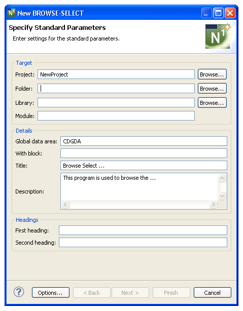
The module parameters are grouped by topic and buttons are available when selecting existing resources. After specifying the first parameter on a panel, messages are displayed indicating the next required parameter. The button will only be enabled when all required parameters have been specified on the current panel have been specified; the button will only be enabled when all required parameters have been specified for the current wizard.
To generate a module
Specify all required parameters and any optional parameters on the first panel for the selected wizard.
Select .
Or:
Select .
The generation process begins. By default, progress is detailed in messages displayed near the bottom of the panel. Once generation is complete, the code is downloaded to the client. The generated source is displayed in the editor and the available user exits are displayed in the Outline view.
Save the generated module(s).
Use standard NaturalONE functionality to upload the generated module(s) to the server.
The following table lists the supplied Natural Construct client generation wizards and where you can find information on the specification parameters for each wizard:
| Wizard | Information |
|---|---|
| BROWSE | Browse/Browse-Select Wizards |
| BROWSE-SELECT | Browse/Browse-Select Wizards |
| BROWSE-SELECT-HELPR | Browse/Browse-Select Wizards |
| BROWSE-SELECT-SUBP | Browse/Browse-Select Wizards |
| BROWSE-SUBP | Browse/Browse-Select Wizards |
| DRIVER | Driver Wizard |
| MAINT | Maint Wizard |
| MENU | Menu Wizard |
| OBJECT-BROWSE-DIALOG | Object-Browse-Dialog Wizard |
| OBJECT-BROWSE-SELECT-SUBP | Object-Browse-Select-Subp Wizard |
| OBJECT-BROWSE-SUBP | Object-Browse-Subp Wizard |
| OBJECT-MAINT-DIALOG | Object-Maint-Dialog Wizard |
| OBJECT-MAINT-ENHANCED-SUBP | Object-Maint-Enhanced-Subp Wizard |
| OBJECT-MAINT-SUBP | Object-Maint-Subp Wizard |
| QUIT | Quit Wizard |
| STARTUP | Startup Wizard |
Notes:
In addition to the standard navigation buttons available at the bottom of the wizard panels, an Options button is available to define generation options.
To define generation options
Select on the wizard specification panel.
The Generation Options window is displayed. For example:
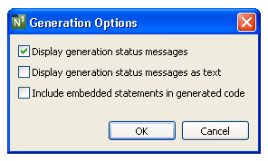
Using this window, you can:
| Task | Procedure |
|---|---|
| Disable the display of generation status messages. | Deselect Display generation status messages. The generation status messages indicate which module is being invoked at each stage of the generation process. |
| Display the generation status messages as text (for example, "starting" and "ending"). | Select Display generation status messages as text. By default, the messages are displayed with arrows "-->" (starting) and "<--" (ending). |
| Write embedded statements to the source buffer as part of the generated module. | Select Include embedded statements in generated code. Embedded statements indicate where the lines of code being written originated and the name of the code frame, generation subprogram, or sample subprogram that produced the code. |
Select to save the generation options.
The specification parameters listed on the wizard panels correspond with those on panels for the Natural Construct models on the server. This section describes the common specifications for the Natural Construct wizards and how to perform common development tasks.
Notes:
This section covers the following topics:
This section describes the specification parameters for the Browse and Browse-Select series of wizards. The following topics are covered:
Note:
The Browse-Select series of wizards is used for screen
examples throughout this section.
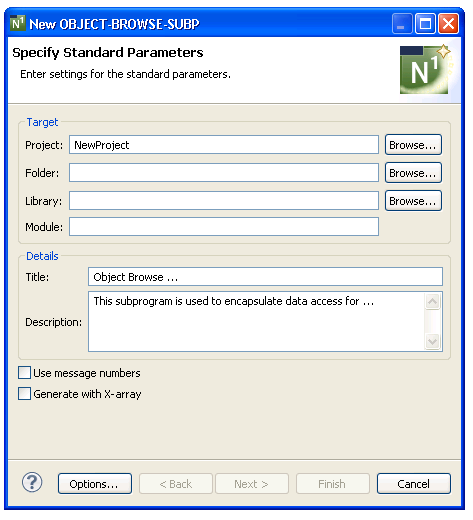
The Specify Standard Parameters panel is displayed when the wizard is invoked; it is similar for all Browse and Browse-Select wizards. For information about these parameters, see Specify Standard Parameters.
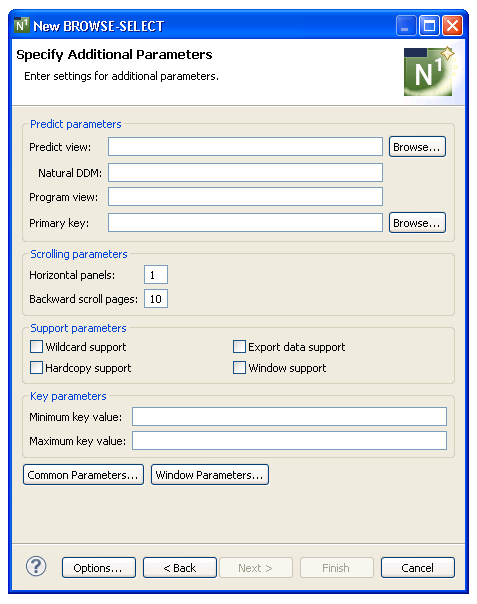
After specifying the standard parameters, select to display the Specify Additional Parameters panel. For example:
To specify additional parameters
Define the following parameters:
| Parameter | Description |
|---|---|
| Predict view | Name of the Predict view used by the generated browse module. Either type the name or select to display the available views for selection. The view must be defined in Predict. |
| Primary key | Name of the primary key by
which scrolling takes place. Either type the name or select
to display the available primary keys for
selection. This key must be defined as a descriptor, superdescriptor, or
subdescriptor in the Predict file definition. Keys
containing MUs (multiple-valued fields) and PEs (periodic groups) are
supported. If this key does not exist in the corresponding
Predict file, a message is displayed.
Note: |
Optionally, you can:
| Task | Procedure |
|---|---|
| Define the name of the data definition module (DDM) corresponding to the primary file. | Type the DDM name in
Natural DDM. If this field is not specified, the DDM name
defaults to the primary file name. The Predict
definition of the primary file determines which fields are included in the
DEFINE DATA section of your generated code. The format of the generated code in
the DEFINE DATA section has the following structure:
1 Primary-file-name VIEW OF Data-definition-module 2 fields pulled from Predict of Primary-file-name |
| Define the name of the view for the primary file for the generated module. | Type the primary file view
name in Program view. This view must be defined in the
LOCAL-DATA user exit or a local data area (LDA).
If this field is not specified, a view is generated containing all fields in the Predict view. The MAX.OCCURS value in Predict determines how many occurrences of MU/PE fields are included on the panel. |
| Change the number of panels used for the generated module. | Type the number of panels in Horizontal panels. The default is 1 panel. |
| Change the maximum number of pages the generated module can scroll. | Type the maximum number of
pages in Backward scroll pages. The default is 10, which
indicates that users can scroll forward and backward within a 10-page range. If
they scroll forward 11 pages, page 1 is forced out of the range and they cannot
scroll back to it.
Note: |
| Enable wildcard processing in the generated module. | Select Wildcard support. Numeric key values are input into an alphanumeric field, which allows the user to enter "*", ">", or "<" |
| Enable records to be exported to a work file in addition to, or instead of, the screen. | Select Export data
support. The work file can then be used in other environments and on
other platforms (for example, in a PC spreadsheet application). To write data
from the generated report to a work file, select the EXPORT-DATA user exit and
define the parameters to export to the work file. The work file number and
delimiter character (used to delimit fields on the report) can be customized
for your site.
Note: |
| Enable the hardcopy facility in the generated module. | Select Hardcopy support. |
| Enable the module output to be displayed in a window, rather than a panel. | Select Window support. By default, the window size is adjusted to its content. The window is placed on the screen so that the field from which the user invoked it remains visible. |
| Define a starting value for the browse. | Type the starting value in
Minimum key value. The combination of the minimum and
maximum key values creates a logical window within the file. The program will
not browse before or after these values.
The minimum key value must be a constant. The specified constant is placed into a variable called #MIN-KEY-VALUE, which can be overridden in the START-OF-PROGRAM user exit. |
| Define an ending value for the browse. | Type the ending value in
Maximum key value. The maximum key value must be a
constant and greater than or equal to the minimum key value. The specified
constant is placed into a variable called #MAX-KEY-VALUE, which can be
overridden in the START-OF-PROGRAM exit.
Note: |
| Define common parameters for the generated module, such as support for direct command processing, message numbers, and password checking. | Select . For information, see Specify Common Parameters. |
| Define window parameters for the generated module. | Select . For information, see Change the Window Settings. |
| Select generation options for the module(s). | Select . For information, see Generation Options. |
Select .
The module is generated using the current specifications. When generation is complete, the available user exits are displayed in the Outline view.
Or:
Select .
The Specify Map Details panel is displayed. For example:
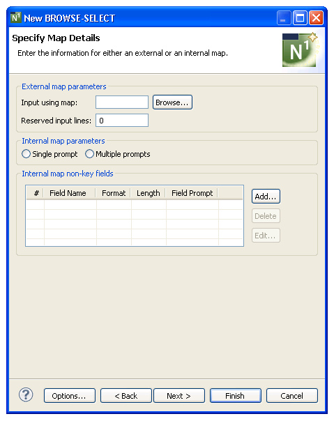
Optionally, you can define details for either an external or internal map.
To specify map details
Define the following optional parameters:
| Parameter | Description |
|---|---|
| Input using map | Name of the layout map used
for the generated module. Either type the name or select
to display the available maps for selection. If a
map is specified, it should be a short map that is displayed at the bottom of
the panel. The CDLAYSC1 layout map is supplied for Browse models. If you do not
specify a layout map, Natural Construct places the
input fields sequentially at the bottom of the panel.
The map is included as part of the END OF PAGE processing to input values that control scrolling. The map must adhere to the following conventions:
When more than one horizontal panel is required, use a different map for each panel. Include an asterisk (*) in the map name (for example, MYMAP*) and the asterisk will be replaced by the panel number during generation (for example, MYMAP1, MYMAP2, MYMAP3). If more than nine horizontal panels are used, the map name cannot exceed six bytes. To support an action/selection column for browse-select modules, include the column on the map as an array called #ACTIONS. Attach the #ACTION-CV control variable to #ACTIONS. To display a list of available actions on the generated panel, include the CDDIALDA.#KD-LINE1 and CDDIALDA.#KD-LINE2 variables on the map. |
| Reserved input lines | Number of lines reserved for input prompts (typically 1, 2, or 3). |
| Single prompt | Enables/disables a single prompt to be displayed for all fields (for example, Date:____ __ __). This option applies when the key is a superdescriptor or redefined in Predict. |
| Multiple prompts | Enables/disables one prompt to be displayed for each field (for example, Year:____ Month:__ Day:__). This option applies when the key is a superdescriptor or redefined in Predict. |
| Internal map non-key fields | Up to eight additional input fields for the browse module. For information, see Specify Field Details. |
Select .
The module is generated using the current specifications. When generation is complete, the available user exits are displayed in the Outline view.
Or:
Select .
The following panel is displayed:
| Wizard | Panel Displayed |
|---|---|
| Browse | Specify Restriction Parameters |
| Browse-Helpr and Browse-Subp | Specify Additional Subprogram Parameters |
| Browse-Select, Browse-Select-Helpr, and Browse-Select-Subp | Specify #ACTION Parameters |
Optionally, you can specify up to eight additional input fields for a browse module. These fields are displayed at the bottom of the generated panel and allow the user to display more information. For example, you can create an additional input field called Detail (format L) to display additional record details. Users can select the Detail field to display the information.
Note:
The additional input fields do not have to be in the
Predict file definition.
This section covers the following topics:
To add a non-key field
Select on the Specify Map Details panel.
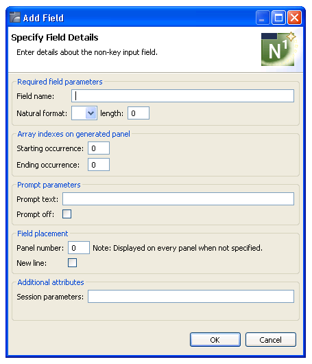
The Specify Field Details window is displayed. For example:
Define the following parameters for the additional field:
| Parameter | Description |
|---|---|
| Field name | Name of the additional input field. |
| Natural format/length | Natural format and length for the field. |
| Starting occurrence | Starting occurrence of an
array variable to place on the generated panel.
Note: |
| Ending occurrence | Ending occurrence of an array variable to place on the generated panel. |
| Prompt text | Text displayed for the field on the generated browse panel. Intensified text must be enclosed within angle (<>) brackets (or whatever attribute character is set for intensify).If you do not specify a field prompt, Natural Construct creates a prompt using the internal name of the input field. |
| Prompt off | Enables/disables the display of the prompt text. |
| Dynamic Attributes | Change the default dynamic attribute characters. For information, see Change the Dynamic Attribute Characters. |
| Panel number | Panel number for the field for the first dimension. If a panel number is not specified, the prompt is displayed on all panels. |
| New line | Enables/disables the display of the input field on a new line. |
| Session parameters | One or more session
parameters for the additional input field, such as Attribute Definition (AD) or
Edit Mask (EM). For example:
AD=I SG=ON EM='>'X HE='HELPR' |
Select to add the field.
To delete a non-key field
Select the field you want to delete on the Specify Map Details panel.
Select .
The field is removed from the Internal map non-key fields table.
To edit a non-key field
Select the field you want to edit on the Specify Map Details panel.
Select .
Or:
Double-click on the row in the Internal map
non-key fields section.
The Specify Field Details window is displayed, showing the current settings for the field.
Edit the field settings.
Select to save the changes.
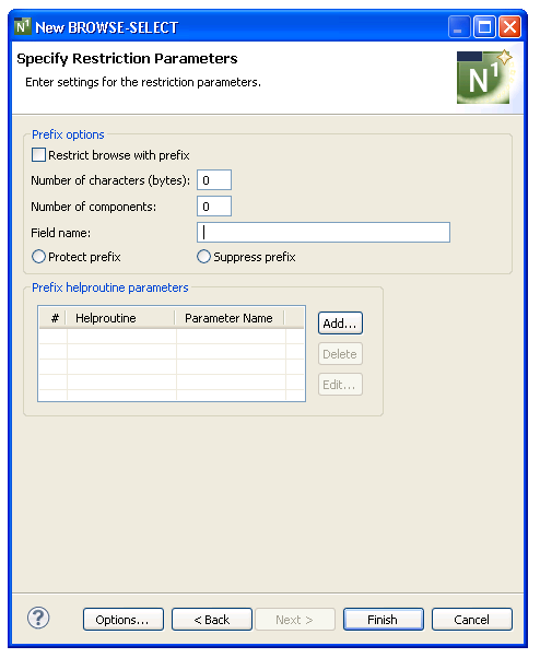
For a browse program, you can optionally limit the generated module to only browse records prefixed by a global variable. If the prefix is a department code, for example, you can restrict the browse to only those orders prefixed by a particular department code by setting the value of the code as a function of a user ID and storing the value in the global data area.
For a browse helproutine or subprogram, you can limit the browse by passing the prefix portion of the key. To display only the lines for a particular order, for example, you can pass the order number (N6) to the subprogram and enter "N6" in the Natural format field on the Specify Additional Subprogram Parameters panel. On the Specify Restriction Parameters panel, mark the Restrict browse with prefix field and enter "6" in the Number of characters (bytes) field.
The following example displays the Specify Restriction Parameters panel for the Browse-Select wizard:
To specify restriction parameters
Define the following optional parameters:
| Parameter | Description |
|---|---|
| Restrict browse with prefix | Enables/disables the
restriction of the browse by prefix. When this option is selected, the browse
is limited to values for which the primary key is prefixed by or equal to the
specified value.
Note: |
| Number of characters (bytes) | Number of bytes of the
primary key to use as the prefix..
Note: |
| Number of components | Number of compound key
components to use as the prefix. You can then use the Prefix
helproutine parameters options to assign the helproutine parameters.
Note: |
| Field name | Name of the field containing
the prefix value. The value must be a valid Natural field name.
When generating a browse helproutine or subprogram, the prefix portion of the key is assumed to be equal to #PDA-KEY (i.e., the value of the key passed to the helproutine or subprogram). To override this default:
The assigned value (instead of #PDA-KEY) will then be used as the value for the prefix portion of the key. |
| Protect prefix | Enables/disables the
protection of the prefix portion of the primary key for the input field. When
this option is selected, the prefix is displayed but cannot be changed.
Note: |
| Suppress prefix | Enables/disables the display
of the prefix portion of the primary key. When this option is selected, the
prefix portion of the primary key is not displayed.
Note: |
| Helproutine parameters | Up to two restriction
helproutine parameters. For information, see
Specify
Prefix Helproutine Parameters.
Note: |
Select .
The modules are generated using the current specifications. When generation is complete, the available user exits are displayed in the Outline view.
Save the generated modules.
At this point, you can:
Use the NaturalONE Testing option to test a subprogram. For information, see Test a Subprogram Directly in Application Testing.
Define user exits for the subprogram. For information, see Defining User Exits.
Use NaturalONE functionality to upload all generated modules to the server.
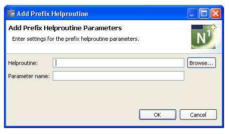
When Number of components is specified on the Specify Restriction Parameters panel, you can optionally attach a helproutine to the prefix of the primary key. This section covers the following topics:
To add a prefix helproutine parameter
Select on the Specify Restriction Parameters panel.
The Add Prefix Helproutine Parameters window is displayed. For example:
Define the following parameters for the additional field:
| Parameter | Description |
|---|---|
| Helproutine | Name of the helproutine for the prefix. To attach a helproutine to the prefix of the primary key, enter the name of the helproutine in this field. You can specify a helproutine for each component. |
| Parameter name | Parameter for the helproutine for each component. Define the help parameters in the LOCAL-DATA user exit. |
Select to add the helproutine.
To delete a prefix helproutine parameter
Select the helproutine you want to delete on the Specify Restriction Parameters panel.
Select .
The helproutine is removed from the Prefix helproutine parameters table.
To edit a prefix helproutine parameter
Select the helproutine you want to delete on the Specify Restriction Parameters panel.
Select .
The Edit Prefix Helproutine window is displayed, showing the current settings for the helproutine.
Or:
Double-click on the row in the Prefix
helproutine parameters section.
Edit the helproutine settings.
Select to save the changes.
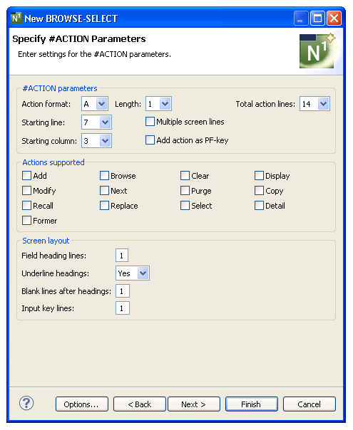
For Browse-Select, Browse-Select-Helpr, and Browse-Select-Subp wizards, theSpecify #ACTION Parameters panel is displayed after the Specify Map Details panel. This panel defines the characteristics of the action/selection field. For example:
To specify #ACTION parameters
Define the following optional parameters:
| Parameter | Description |
|---|---|
| Action format/length | Natural format and length of the action/selection field. The default is A1. |
| Total action lines | Total number of action lines displayed on the generated panel. This number corresponds to the maximum number of database records. The default is 14 lines. |
| Starting line | Line number on which the action column begins. This number corresponds to the first line containing database information (after the panel and field heading lines). The default is 7. |
| Multiple screen lines | Determines whether each
record requires more than one line. For example:
Address: Number-Street City, Province Country, Postal Code |
| Starting column | Number of the column in which the action/selection fields are displayed (when not using an external map). This number determines the placement of the action/selection entries. The default is 3. |
| Add action as PF-key | Enables a PF-key for the Add
action (by default, PF4).
When generating a browse-select panel, you must decide how users will add records to a file: by entering "A" in the Action field or by pressing an Add PF-key. The first method is effective when adding records to existing files containing one or more records; the second method allows the user to select the Add PF-key while the cursor is positioned anywhere on the screen and add a record to an empty file. |
| Actions supported | Actions enabled for the generated browse-select panel. By default, no actions are supported. |
| Screen layout | The parameters in this section are used to build the screen layout when not using a predefined map. |
| Field heading lines | Number of field heading lines. The default is one line. |
| Underline headings | Determines whether field headings are displayed with a line under them. By default, field headings are underlined. |
| Blank lines after headings | Number of blank lines between the field headings and the data region. The default is one line. |
| Input key lines | Number of lines reserved at
the bottom of the panel for input keys and additional fields. The default is
one for input keys, plus the number of lines for additional input fields that
begin on new lines.
Note: |
Select .
The module is generated using the current specifications. When generation is complete, the available user exits are displayed in the Outline view.
Or:
Select .
The following panel is displayed:
| Wizard | Panel Displayed |
|---|---|
| Browse-Select | Specify Restriction Parameters |
| Browse-Select-Helpr or Browse-Select-Subp | Specify Additional Subprogram Parameters |
The Specify Additional Subprogram Parameters panel is displayed after the Specify Map Details panel for Browse-Helpr and Browse-Subp wizards and after the Specify #ACTION Parameters panel for Browse-Select-Helpr and Browse-Select-Subp wizards.
When generating a helproutine, the following information is displayed on the Specify Additional Subprogram Parameters panel:
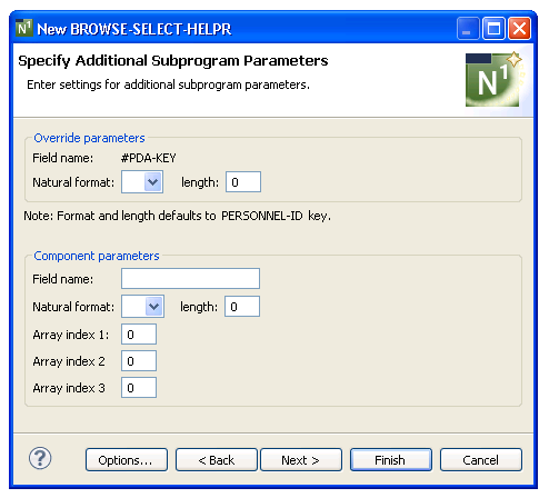
When generating a subprogram, the following information is displayed on the Specify Additional Subprogram Parameters panel:
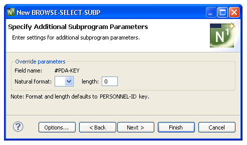
Use this panel to override the format and/or length of the passed parameter or pass an additional parameter to the helproutine. The key for the browse-select may differ from the key for the calling program. If the key differs, indicate the format and length of the passed key on this panel. Also indicate the name of any additional helproutine parameter, as well as its format and length.
Use the top portion of this panel to specify the format and length of the help field (if it is different from that of the primary browse key).
When generating a helproutine, use the bottom portion of this panel to specify additional parameters. If no additional parameters are specified, the generated helproutine only has one parameter (#PDA-KEY), which contains the contents of the input field to which the helproutine is attached. If the helproutine changes the value of #PDA-KEY, the altered value is displayed in the input field when the helproutine returns control to the INPUT statement.
To specify additional subprogram parameters
Define the following parameters:
| Parameter | Description |
|---|---|
| Field name | Name of the primary key. By default, #PDA-KEY is displayed. |
| Natural format and length | Natural format and length of the passed field (if it is different from that of the key being browsed). This format becomes the format for the #PDA-KEY field. |
| Component parameters | |
| Field name | Name of the additional parameter. |
| Natural format and length | Natural format and length of the additional parameter. Any valid combination of format, length, and decimal positions under Natural is allowed. |
| Array index 1, 2, and 3 | Array dimensions. To declare the additional parameter as an array, enter the array dimensions in the 1, 2, and 3 fields. |
Select .
The module is generated using the current specifications. When generation is complete, the available user exits are displayed in the Outline view.
Or:
Select .
The Specify Restriction Parameters panel is displayed. For information, see Specify Restriction Parameters.
This section describes the specification parameters for the Driver wizard. This wizard generates a module that executes a helproutine or subprogram for testing purposes. The Driver wizard generates an INPUT statement — you supply the parameters to execute the helproutine or subprogram. The wizard also generates headings and PF-key names according to the value of *Language.
This section covers the following topics:
Notes:
The Specify Standard Parameters panel is the only specification panel for the Driver wizard.
To specify standard parameters
Open the context menu in the Navigator view for the NaturalONE project in which you want to generate the modules.
Or:
Open the context menu in the
Navigator view for the library in which you want to
generate the modules.
Select .
The Specify Standard Parameters panel is displayed. For example:
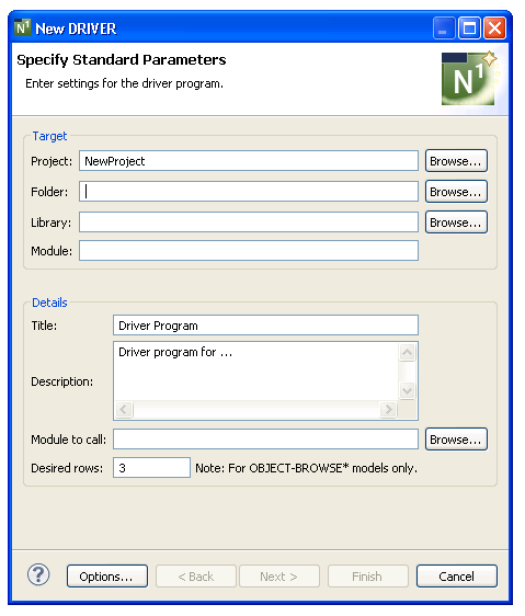
Many of the parameters on this panel are common to most wizards. For information, see Specify Standard Parameters.
Define the following parameter:
| Parameter | Description |
|---|---|
| Module to call | Name of the helproutine or subprogram you want to execute using this driver program. Either type the name or select to display the available modules for selection. A compiled version of the module must exist in the current library or in the steplib chain. |
Optionally, you can:
| Task | Procedure |
|---|---|
| Change the number of rows defined in the row array in the generated data PDA. | Type the new number in
Desired rows. By default, three rows are defined.
Note: |
Select .
The driver program is generated using the current specifications. When generation is complete, the available user exits are displayed in the Outline view.
Save the generated module.
At this point, you can:
Define user exits for the driver program. For information, see Defining User Exits.
Use NaturalONE functionality to upload all generated modules to the server.
Natural Construct provides two alternatives to generate a maintenance process:
Use the Maint wizard. This wizard creates fast prototypes or simple maintenance processes that are temporary. The process is faster to implement because you need only create one or two Natural objects: the maintenance program generated by the Maint wizard and, optionally, a map. Conversely, because dialog and data are combined, the generated maintenance program is not as easy to modify as the subprograms generated by the Object wizards.
Use the Object wizards: Object-Maint-Subp or Object-Maint-Enhanced-Subp (which also generates the object PDA and restricted PDA) and, optionally, the Object-Maint-Dialog wizard. These wizards generate all the functionality needed for application development at the production level. The separation of dialog and data makes future changes to the maintenance process easier to implement.
The differences between the code generated by the two wizards include:
| Maint Wizard | Object Wizards |
|---|---|
| Maintains one or two levels of files: primary and secondary. | Maintain up to four levels of files: primary, secondary, tertiary, and quaternary. |
| Supports one scrolling region. | Support multiple scrolling regions. |
| Does not support a link between scrolling regions on multiple panels. | Support a link between scrolling regions on multiple panels. |
| Does not provide automatic cursor repositioning after an error. (This functionality is available within user exits.) | Provide automatic cursor repositioning after an error. |
This section describes the Maint wizard, which generates a program that maintains a file using a unique key and, optionally, a related secondary file. The Maint wizard generates the code necessary to maintain all the fields for an object, as well as scroll through the MU/PE fields of a primary file or the records of a secondary file. The following topics are covered:
Note:
By default, a maintenance program generated using the Maint
wizard prompts users to press the Enter key to confirm a Purge action. If you
specify a confirmation key other than Enter, the program will force
confirmation of Add, Modify, and Purge actions. For a description of how to
change the confirmation key, see Confirmation Key Setup,
Natural Construct Generation.
The Specify Standard Parameters panel is displayed when the wizard is invoked; it is similar for most wizards.
To specify standard parameters
Open the context menu in the Navigator view for the NaturalONE project in which you want to generate the modules.
Or:
Open the context menu in the
Navigator view for the library in which you want to
generate the modules.
Select .
The Specify Standard Parameters panel is displayed. For example:
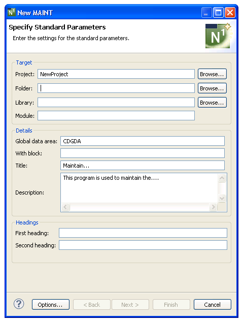
For information about these parameters, see Specify Standard Parameters. After specifying the standard parameters, select to display the Specify Additional Parameters panel. For example:
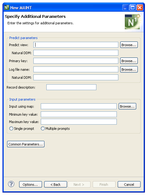
Use this panel to define additional parameters for your maintenance program.
To specify additional parameters
Define the following parameters:
| Parameter | Description |
|---|---|
| Predict view | Name of the Predict view used by the generated browse module. Either type the name or select to display the available views for selection. The view must be defined in Predict. |
| Primary key | Name of the primary key by
which scrolling takes place. Either type the name or select
to display the available primary keys for
selection. This key must be defined as a descriptor, superdescriptor, or
subdescriptor in the Predict file definition. Keys
containing MUs (multiple-valued fields) and PEs (periodic groups) are
supported. If this key does not exist in the corresponding
Predict file, a message is displayed.
Note: |
Optionally, you can:
| Task | Procedure |
|---|---|
| Define the name of the data definition module (DDM) corresponding to the primary file. | Type the DDM name in
Natural DDM. If this field is not specified, the DDM name
defaults to the primary file name. The Predict
definition of the primary file determines which fields are included in the
DEFINE DATA section of your generated code. The format of the generated code in
the DEFINE DATA section has the following structure:
1 Primary-file-name VIEW OF Data-definition-module 2 fields pulled from Predict of Primary-file-name |
| Provide the name of a log file to perform update logging for the generated maintenance program. | Type a view name in Log file name or select to display the available views for selection. All fields in the primary file that have matching fields in the log file are written to the log records. Other fields, such as LOG-DATE and LOG-USER, must also appear in the log view. |
| Define the name of the data definition module (DDM) corresponding to the log file (when it is not the same as the log file name). | Type the DDM name in Natural DDM. If this field is not specified, the DDM name defaults to the log file name. The update log file must be a view of the log file DDM. |
| Provide a description of the record to be used in messages. | Type the description used in messages in Record description. By default, "Record" is displayed and messages are displayed in the form: "Record not found" and "Record displayed". |
| Provide the name of the layout map used for the generated maintenance program. | Type the name of the map in Input using map or select to display the available maps for selection. |
| Define a starting value for the browse. | Type the starting value in
Minimum key value. The combination of the minimum and
maximum key values creates a logical window within the file. The program will
not browse before or after these values.
The minimum key value must be a constant. The specified constant is placed into a variable called #MIN-KEY-VALUE, which can be overridden in the START-OF-PROGRAM user exit. |
| Define an ending value for the browse. | Type the ending value in
Maximum key value. The maximum key value must be a
constant and greater than or equal to the minimum key value. The specified
constant is placed into a variable called #MAX-KEY-VALUE, which can be
overridden in the START-OF-PROGRAM exit.
Note: |
| Display a single prompt for all fields on the generated panel. | Select Single prompt. This option enables/disables a single prompt to be displayed for all fields (for example, Date:____ __ __). It applies when the key is a superdescriptor or redefined in Predict. |
| Display multiple prompts for all fields on the generated panel. | Select Multiple prompts. This option enables/disables one prompt to be displayed for each field (for example, Year:____ Month:__ Day:__). It applies when the key is a superdescriptor or redefined in Predict. |
| Define common parameters for the generated module, such as support for direct command processing, message numbers, and password checking. | Select . For information, see Specify Common Parameters. |
| Select generation options for the module(s). | Select . For information, see Generation Options. |
Select .
The Specify Additional Input Parameters panel is displayed. For example:
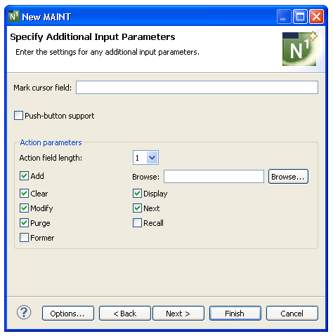
Use this panel to define any additional input parameters for your maintenance program.
To specify additional input parameters
Define any or none of the additional parameters.
Using this panel, you can:
| Task | Procedure |
|---|---|
| Define the field marked by default on the generated maintenance panel when an error occurs. | Type the name in Mark cursor field. To avoid ambiguity, fully qualify the field name with a structure name. |
| Present actions as cursor-sensitive push buttons. | Select Push-button support. Users can press the Tab key to move from action to action. For more information about implementing actions as push buttons, see the description of the #KD-LINES(*) variable in Variables You Can Use with a Maint Model Map, Natural Construct Generation. |
| Change the length of the field used for #ACTION names. By default, the field is 1 character in length. | Select another length in Action field length (possible lengths are 1, 2, or 3). For example, to use "DI" for the Display action, select "2" in this field. |
| Change the default actions generated for the maintenance program. By default, all actions except Recall and Former are selected. | Select or deselect any of the
following actions:
|
| Provide the name of the module used to perform the Browse action. | Select for the Browse action field and select the name of the module. |
| Select generation options for the module(s). | Select . For information, see Generation Options. |
Select .
The maintenance program is generated using the current specifications. When generation is complete, the available user exits are displayed in the Outline view.
Or:
Select .
The Specify Secondary File Parameters panel is displayed. For example:
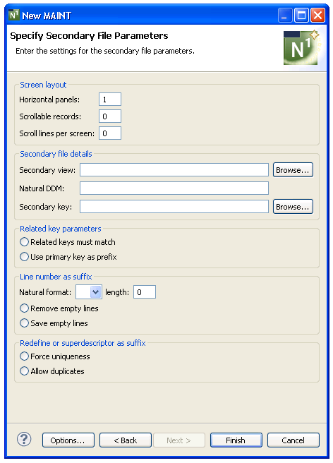
Use this panel to define secondary parameters when the program maintains two files, periodic groups (PEs), multiple-valued fields (MUs), or uses more than one panel of input data.
To specify secondary file parameters
Define any or none of the secondary file parameters.
Using this panel, you can:
| Task | Procedure |
|---|---|
| Define the number of panels required to specify all data in the view. By default, "1" is displayed. | Type the number of panels in Horizontal panels. (The view may involve either one or two files.) The #PANEL value ranges from 1 to the number specified in this field. This option is used in conjunction with the Input using map field. |
| Define the maximum number of secondary file records that can be read or saved. By default, "0" is displayed. | Type the number of secondary
file records in Scrollable records. If scrolling MU/PE
fields in the primary file is supported, this value represents the highest
value that may be scrolled.
Notes:
|
| Define the number of MU/PE elements or secondary file records that can be displayed on the panel at one time. By default, "0" is displayed. | Type the number of elements
or records in Scroll lines per screen.
Note: |
| Specify the name of a Predict view that is coupled with the primary file for the maintenance program. | Type the name of the file in
Secondary view or select to
display a window listing the existing files for selection. A file definition
for the file must exist in Predict.
If you specify a secondary view, you must also specify the maximum number of secondary file records that can be read or saved in Scrollable records, the number of scroll lines per panel in Scroll lines per screen, and select a secondary key in Secondary key. |
| Specify the name of the DDM (data definition module) for the secondary file. | Type the name of the DDM in
Natural DDM. All fields in the secondary file must be in
this DDM.
Note: |
| Specify the name of the key in the secondary file that is related to the key in the primary file. | Type the name of the key in Secondary key or select to display a window listing the existing keys for selection. The key can be a descriptor, superdescriptor, or subdescriptor. |
| Specify that the secondary file key must be identical to the primary file key. | Select Related keys must match. |
| Specify that the key of the primary file is a prefix of the secondary file key (secondary file records are always displayed in the secondary key order). | Select Use primary
key as prefix. If the primary file key is a prefix of the secondary
file key, specify how the relationship between the two files is established by
using either the Line number as suffix options (Remove empty
lines and Save empty lines) or the Redefine or
superdescriptor as suffix options (Force uniqueness and
Allow duplicates). The biggest difference between the two
options is that for the Line number as suffix options, you do not need to enter
the suffix value for the secondary key. Because the suffix value is a line
number, the suffix is determined during each update session within the
generated program. For all four options, the secondary file key can be either a
descriptor or a superdescriptor.
Note: |
| Specify the Natural format and length of the line number (N4, I2, for example). | Select the format in Natural format and type the length in length. The generated program assumes the secondary file key is made up of the primary file key value, plus a line number. The value of the suffix can be displayed on the panel, but cannot be modified. |
| Specify that the suffix components of the secondary file keys are renumbered (starting at 1) after an occurrence of the view is saved. | Select Remove empty lines. |
| Specify that the suffix components of the secondary file keys are not renumbered after an occurrence of the view is saved. | Select Save empty lines. |
| Use the redefinition of the secondary key field in Predict to determine the suffix (when the secondary key suffix is more than a line number). | Select Force uniqueness. The secondary key suffixes for each secondary file record should be modifiable when displayed on the map. The generated program also ensures a unique secondary file key. If the secondary key is a superdescriptor, place the trailing fields (beyond the primary key length) on the map. |
| Specify that the generated program does not check the secondary key for duplicates. | Select Allow duplicates. |
| Select generation options for the module(s). | Select . For information, see Generation Options. |
Select .
The maintenance program is generated using the current specifications. When generation is complete, the available user exits are displayed in the Outline view.
Save the generated module.
At this point, you can:
Define user exits for the maintenance program. For information, see Defining User Exits.
Use the NaturalONE functionality to test the program.
Use NaturalONE functionality to upload the generated program to the server.
This section describes the specification parameters for the Menu wizard. This wizard generates a program that presents users with several choices in the form of a menu. The user enters a code for one of the choices to invoke a predefined function. You can also include additional fields on a menu, which may or may not require input.
This section covers the following topics:
To specify standard parameters
Open the context menu in the Navigator view for the NaturalONE project in which you want to generate the modules.
Or:
Open the context menu in the
Navigator view for the library in which you want to
generate the modules.
Select .
The Specify Standard Parameters panel is displayed. For example:
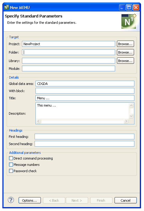
Many of the parameters on this panel are common to most wizards. For information, see Specify Standard Parameters. For information about the Additional parameters options, see Specify Common Parameters.
After specifying the standard parameters, select to display the Specify Additional Parameters panel. For example:
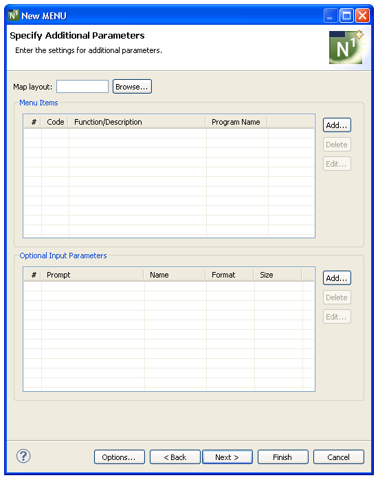
Use this panel to define parameters for the menu, such as the name of a map layout, the available codes and functions, and the names of the programs to FETCH (if entering a menu code invokes a program). Optionally, you can link up to four additional parameters to their associated menu functions.
Tip:
Although a map layout is not required for a menu program, it
can give a consistent, tailored appearance to your applications.
To specify additional parameters
Select for Menu items.
The Add Row window is displayed. For information, see Add a Row of Menu Items.
Optionally, you can:
| Task | Procedure |
|---|---|
| Provide the name of the layout map used for the generated menu program. | Type the name of the map in Map layout or select to display the available maps for selection (.NSM file extension). |
| Link up to four additional parameters to their associated menu functions. | Select for Optional input parameters. For information, see Define Optional Input Parameters. |
Select .
The menu program is generated using the current specifications. When generation is complete, the available user exits are displayed in the Outline view.
Save the generated module.
At this point, you can:
Define user exits for the menu program. For information, see Defining User Exits.
Use NaturalONE functionality to upload all generated modules to the server.
This section describes how to define details for each row on your menu. The following topics are covered:
To add a row of menu items
Select for the Menu items table on the Specify Additional Parameters panel.
Add Row window is displayed. For example:
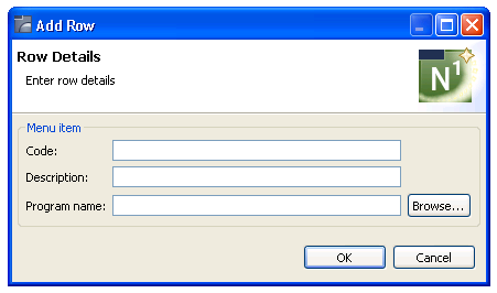
Define the following parameters for the menu row:
| Field | Description |
|---|---|
| Code | One or two-character code users must enter to invoke the menu function. |
| Description | Function code descriptions displayed on the generated menu. If you are not using a layout map, you must provide a description for all codes specified in the Code field. The descriptions can be up to 45 characters in length. |
Optionally, you can:
| Task | Procedure |
|---|---|
| Provide the name of a program to FETCH (if entering a menu code invokes a program). | Type the name of the program
in Program name or select to
display the available programs for selection (.NSP file extension).
Note: |
Select to add the row.
Perform steps 1, 2, and 3 until all menu rows have been added.
To delete a row of menu items
Select the menu option you want to delete in Menu items on the Specify Additional Parameters panel.
Select .
The row is removed from the Menu items table.
To edit a row of menu items
Select the menu option you want to edit in Menu items on the Specify Additional Parameters panel.
Select .
Or:
Double-click on the row in the Menu
items table.
The Edit Row window is displayed, showing the current settings for the panel.
Edit the row settings.
Select to save the changes.
This section describes how to define optional input parameters, as well as how to link up to four parameters to their associated menu functions. (The majority of the menus will not use this feature.) The following topics are covered:
To add an optional input parameter
Select for the Optional input parameters table on the Specify Additional Parameters panel.
Add Optional Parameter window is displayed. For example:
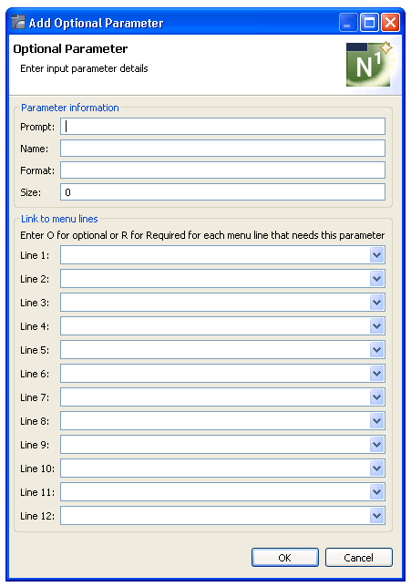
Define the following fields for the optional parameter:
| Field | Description |
|---|---|
| Prompt | Prompt displayed on the menu for the parameter. |
| Name | Name of a Natural internal variable to associate with the prompt. This variable checks the Required/Optional field to ensure that valid data is entered. |
| Format | Single-character alphabetical abbreviation for the Natural format of the specified variable (for example, N). |
| Size | Numeric length of the prompt. |
Optionally, you can:
| Task | Procedure |
|---|---|
| Provide the names of menu functions to be linked to the additional field. | Type the name of the field in Line n and select "R" (required) or "O" (optional). This link will provide a cross reference between the optional parameter and the menu functions. |
Select to add the parameter.
To delete an optional input parameter
Select the parameter you want to delete in Optional input parameters on the Specify Additional Parameters panel.
Select .
The row is removed from the Optional input parameters table.
To edit an optional input parameter
Select the parameter you want to edit in Optional input parameters on the Specify Additional Parameters panel.
Select .
Or:
Double-click on the row in the Optional input
parameters table.
The Edit Optional Parameter window is displayed, showing the current settings for the parameter.
Edit the parameter settings.
Select to save the changes.
This section describes the specification parameters for the Object-Browse-Dialog wizard. This wizard generates a character-based user interface to use with object-browse subprograms.
Because a browse module can be transformed into an object-browse subprogram and object-browse dialog program, and because the browse module has different PF-keys and actions and contains both UI and data access, you must consider how the Object-Browse-Dialog wizard works with a transformed object-browse subprogram versus one that was not transformed. If a browse module was transformed, the object-browse dialog program was generated automatically and there is no need to create one (but you can regenerate the dialog program). To differentiate between the two types in this section, these modules are referred to as a transformed object-browse dialog program versus an object-browse dialog program.
This section covers the following topics:
Note:
For more information, refer to Object-Browse-Dialog
Model, Natural Construct Object
Models.
The Specify Standard Parameters panel is displayed when the wizard is invoked; it is similar for all Object-Browse wizards.
To specify standard parameters
Open the context menu in the Navigator view for the NaturalONE project in which you want to generate the modules.
Or:
Open the context menu in the
Navigator view for the library in which you want to
generate the modules.
Select .
The Specify Standard Parameters panel is displayed. For example:
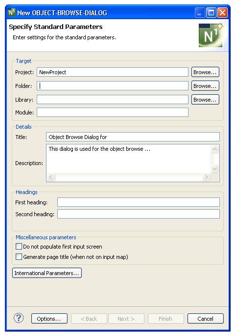
Many of the parameters on this panel are common to most wizards. For information, see Specify Standard Parameters. Optionally, you can use this panel to:
| Task | Procedure |
|---|---|
| Suppress the population of fields with default data on the first input screen. | Select Do not populate first input screen. This option indicates whether default data is automatically entered into fields on the first input screen. It can be used to provide consistency between Natural Construct-generated browse and object-browse modules. By default, the first input screen is not populated for a transformed object-browse dialog program and is populated for a generated object-browse dialog program. |
| Generate a page title when it is not on the input map. | Select Generate a page title (when not on input map). This option indicates whether to automatically code the page title when a map is not being used. By default, the page title is coded for a transformed object-browse dialog program and is not coded for a generated object-browse dialog program. |
| Define the language in which to display text on the generated panel(s). | Select . For information, see Specify International Parameters. |
Select .
The Specify Additional Parameters panel is displayed. For example:
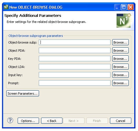
Use this panel to define parameters for the related object-browse subprogram and, optionally, to define screen parameters. The generated object-browse dialog uses this subprogram to retrieve records for display.
To specify additional parameters
Type the name of the subprogram used to retrieve records for display in Object-browse subp or select to display the available subprograms for selection.
Type the name of the logical key by which scrolling takes place in Input key or select to display the available logical keys for selection.
The specified key must be defined in the key PDA. For a transformed object-browse dialog program, the input key begins with A- (Ascending). To preserve the browse ascending and descending functionality, two keys are generated for the primary browse key: one that begins with A- and another that begins with D- (Descending). To expose this functionality to the end user, variables must be set in the START-OF-PROGRAM user exit.
Optionally, you can define the following parameters:
| Parameter | Description |
|---|---|
| Object PDA | Object parameter data area (PDA) used by the specified object-browse subprogram. By default, the wizard will determine the name of the PDA based on the subprogram name. Alternatively, you can type the name or select to display the available data areas for selection (.NSA file extension). |
| Key PDA | Name of the key PDA used by the specified object-browse subprogram. The key PDA is comprised of all fields that are components of the logical keys supported by the subprogram. By default, the wizard will determine the name of the PDA based on the subprogram name. Alternatively, you can type the name or select to display the available data areas for selection (.NSA file extension). |
| Object LDA | Name of the object local data area (LDA) used by the generated dialog program. The object LDA contains the default field headings used when generating user exits. Either type the name or select to display the available data areas for selection (.NSL file extension). |
| Prompt | Field name displayed for the input key on the generated panel. If a field name is not provided, the default name will be used. Either type the name or select to display the available SYSERR numbers for selection. For information, see Select a Message Number. |
| Screen Parameters | Specify the language used to display text on the generated panels. See Specify Screen Parameters. |
Select .
The modules are generated using the current specifications. When generation is complete, the available user exits are displayed in the Outline view.
Or:
Select .
The Specify Specific Parameters panel is displayed. For example:
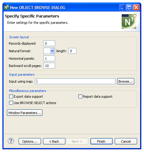
Use this panel to define the screen layout, map name, and support for exporting records to a work file or printer. You can also use this panel to change the style of actions used and the window settings.
To specify specific parameters
Define the following optional parameters:
| Parameter | Description |
|---|---|
| Records displayed | Number of records displayed on the screen at one time (by default, the generated dialog program displays 10 records at one time). |
| Natural format/length | Natural format and length for the selection column (for example, A1). |
| Horizontal panels | Number of horizontal panels used for the generated dialog program (by default, one panel is used). |
| Backward scroll pages | Maximum number of scroll pages within which users can scroll forward and backward (by default, 10 scroll pages). |
| Input using map | Name of the layout map used by the generated dialog program. Either type the name or select to display the available maps for selection (.NSM file extension). |
| Export data support | If this option is selected, records are exported to a work file (instead of the screen). |
| Report data support | If this option is selected, records are exported to a local printer (instead of the screen). |
| Use BROWSE-SELECT actions | If this option is selected,
the generated dialog program uses the same actions as those used by a
BROWSE-SELECT-generated module.
Note: |
| Window Parameters | Specify window parameters. For information, see Change the Window Settings. |
Select .
The modules are generated using the current specifications. When generation is complete, the available user exits are displayed in the Outline view.
Save the generated modules.
At this point, you can:
Define user exits for the dialog program. For information, see Defining User Exits.
Use NaturalONE functionality to upload all generated modules to the server.
This section describes the specification parameters for the Object-Browse-Select-Subp wizard. This wizard generates a subprogram similar in functionality to a subprogram generated by the Browse-Select-Subp model. Both subprograms allow users to update multiple rows at one time. The primary difference between the two is that an object-browse-select subprogram can accommodate a client/server environment and you can use a subprogram proxy to access the generated code as a business service.
This section covers the following topics:
Note:
For more information, refer to
Object-Browse-Select-Subp Model, Natural Construct
Object Models.
The Specify Standard Parameters panel is displayed when the wizard is invoked; it is similar for all Object-Browse wizards.
To specify standard parameters
Open the context menu in the Navigator view for the NaturalONE project in which you want to generate the modules.
Or:
Open the context menu in the
Navigator view for the library in which you want to
generate the modules.
Select .
The Specify Standard Parameters panel is displayed. For example:
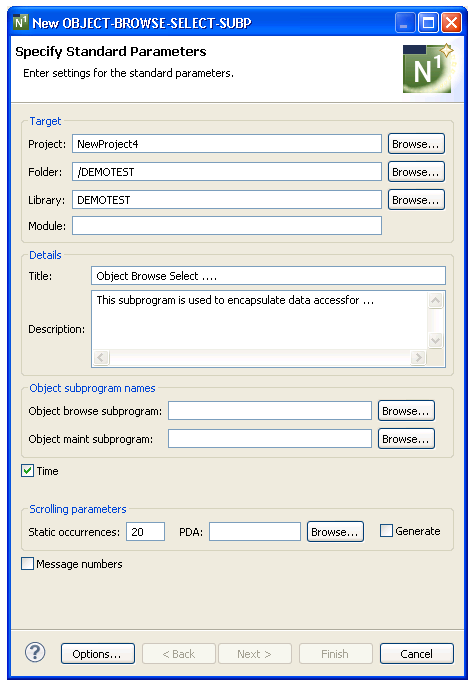
Many of the parameters on this panel are common to most wizards. For information, see Specify Standard Parameters.
Define the following parameters:
| Parameter | Description |
|---|---|
| Object-browse | Name of the subprogram used
to browse this object. Either type the name of the subprogram or select
to display the available subprograms for
selection.
Note: |
| PDA | Name of the parameter data
area associated with the static occurrences value for scrolling parameters. By
default, the PDA name contains the first five characters of the module name and
the number of static occurrences (for example, BCUSTS20). Either type the name
or select to display the available data areas for
selection.
Note: |
Optionally, you can:
| Task | Procedure |
|---|---|
| Define an object-maintenance subprogram that will be used to maintain the object. | Type the name of the
object-maint subprogram in Object-maint or select
to display a window listing the existing
subprograms for selection. The subprogram must currently exist.
The object-maintenance subprogram cannot process intra-object relationships. This allows the data presented to the client to be manageable and all data to be modifiable. Note: |
| Restrict the generation of code to time how long a business service takes to execute. | De-select
Time.
By default, this option is selected and code is generated to time how long a business service takes to execute. The result is returned in the business service message. |
| Change the number of rows processed and sent across the network at one time (by default, 20, unless the rows are extremely large). | Type the new number in
Static occurrences. The PDA (parameter data area)
associated with the static occurrences hard codes this value (which is used to
identify the V value in the object-browse
subprogram) in the object-browse-select subprogram.
To identify the number of occurrences in this PDA, the default PDA name contains the first five characters of the module name and the number of static occurrences (for example, "BCUSTS20" when the static occurrences value is "20"). Note: |
| Use message numbers for all REINPUT and INPUT messages. | Select Use message
numbers. When this option is selected, message numbers rather than
message text will be used for all REINPUT and INPUT messages.
Note: |
Select .
The Specify Additional Parameters panel is displayed. For example:
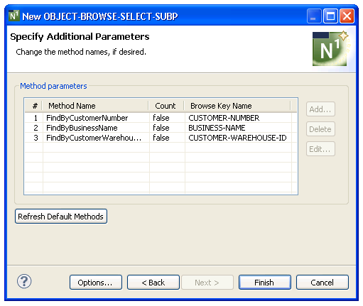
This panel displays the names of the methods and browse keys used to determine the sort order for records returned by the object-browse subprogram (specified on the first wizard panel).
Use this panel to rename the default methods, if desired.
To rename the default methods
Select the method you want to rename in the Method parameters section.
Select .
The Edit Method Name window is displayed. For example:
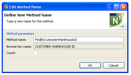
Change the name of the method in Method name.
Select .
The new name is displayed in the Method parameters section.
Select .
The modules are generated using the current specifications. When generation is complete, the available user exits are displayed in the Outline view.
Save the generated modules.
At this point, you can:
Use the NaturalONE Testing option to test a subprogram. For information, see Test a Subprogram Directly in Application Testing.
Define user exits for the subprogram. For information, see Defining User Exits.
Use NaturalONE functionality to upload all generated modules to the server.
This section describes the specification parameters for the Object-Browse-Subp wizard. This wizard generates the browse subprogram for an object, as well as three parameter data areas:
Object PDA (defines the returned row data)
Key PDA (defines the search key values)
Restricted PDA (defines private data used internally by the browse object to maintain context)
This section covers the following topics:
Note:
For more information, refer to Object-Browse-Subp
Model, Natural Construct Object
Models.
The Specify Standard Parameters panel is displayed when the wizard is invoked; it is similar for all Object-Browse wizards.
To specify standard parameters
Open the context menu in the Navigator view for the NaturalONE project in which you want to generate the modules.
Or:
Open the context menu in the
Navigator view for the library in which you want to
generate the modules.
Select .
The Specify Standard Parameters panel is displayed. For example:
Many of the parameters on this panel are common to most wizards. For information, see Specify Standard Parameters. Optionally, you can:
| Task | Procedure |
|---|---|
| Use message numbers for all REINPUT and INPUT messages. | Select Use message
numbers. When this option is selected, message numbers rather than
message text will be used for all REINPUT and INPUT messages.
Note: |
| Generate the object (row) PDA with X-array support. | Select Generate with X-array. When this option is selected, the object PDA will be generated with (1:*) declarations instead of (1:V) for top-level rows; any arrays nested within top-level rows will be generated as defined in Predict. |
Select .
The Specify Additional Parameters panel is displayed. For example:
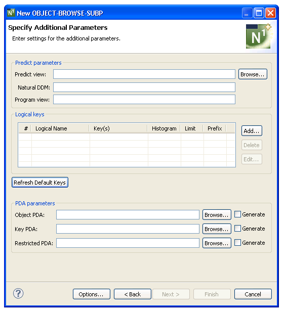
Use this panel to define additional parameters for your object-browse subprogram.
To specify additional parameters
Define the following parameters:
| Parameter | Description | Required/Optional/Conditional |
|---|---|---|
| Predict view | Name of the Predict view used by the generated subprogram. The view must be defined in Predict. Either type the name or select to display the available views for selection. | Required |
| Natural DDM | Name of the data definition
module (DDM) corresponding to the primary file. If this field is not specified,
the DDM name defaults to the primary file name. The
Predict definition of the primary file determines
which fields are included in the DEFINE DATA section of the generated code. The
format of the generated code in the DEFINE DATA section has the following
structure:
1 primary-file-name VIEW OF data-definition-module 2 fields pulled from Predict of primary-file-name |
Optional |
| Program view | View name of the primary file
for the generated subprogram. This view must be defined in the LOCAL-DATA user
exit or a local data area (LDA).
If this field is not specified, a view is generated containing all fields in the Predict view. The MAX.OCCURS value in Predict determines how many occurrences of MU/PE fields are included on the panel. |
Optional |
| Logical keys | Up to six logical keys to determine the sort order for records returned by the object-browse subprogram. For information, see Specify Key Details. | Optional |
| Refresh Default Keys | Retrieves the default key parameters for the specified Predict view and lists them in the Logical keys table. | Optional |
| Object PDA | Object parameter data area
(PDA) that defines the rows returned to the object-browse subprogram and the
columns within each row. Either type the name or select
to display the available PDAs for selection.
Alternatively, you can select Generate to have the data
area generated by the wizard.
The generated object PDA contains one column for each field defined in the specified Predict view (as well as additional columns). You can remove any fields that are not components of the primary key. Note: |
Required |
| Key PDA | Key PDA that contains all of
the components contained in the logical keys, as well as a unique ID field.
Either type the name or select to display the
available PDAs for selection. Alternatively, you can select
Generate to have the data area generated by the wizard.
Note: |
Required |
| Restricted PDA | Restricted PDA that stores
data, such as the last sort key, the last starting value, the last row
returned, etc. so that the next set of consecutive records is returned to the
caller. Either type the name or select to display
the available PDAs for selection. Alternatively, you can select
Generate to have the data area generated by the wizard.
Notes:
|
Required |
Select .
The modules are generated using the current specifications. When generation is complete, the available user exits are displayed in the Outline view.
Save the generated modules.
At this point, you can:
Use the NaturalONE Testing option to test a subprogram. For information, see Test a Subprogram Directly in Application Testing.
Define user exits for the subprogram. For information, see Defining User Exits.
Use NaturalONE functionality to upload all generated modules to the server.
Optionally, you can specify up to six logical keys to determine the sort order for records returned by the object-browse subprogram. The calling program indicates the sort order by assigning CDBRPDA.SORT-KEY. If a sort key value is not assigned, the first logical key is used as the default.
The logical key names can map to as many as five components. If a logical key contains only one component, the logical key name is optional. If you do not specify a logical key name, this field defaults to the name of the key component.
If the key field contains MU or PE fields, the rows returned also contain an index value that identifies which occurrence of the MU/PE field satisfies the Read condition.
This section covers the following topics:
To add a logical key
Select on the Specify Additional Parameters panel.
The Specify Key Details window is displayed. For example:
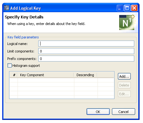
Define the following parameters for the additional key field:
| Parameter | Description |
|---|---|
| Logical name | Name of the logical key for which you are defining details. |
| Limit components | Number of components of a
superdescriptor (compound key) to use in the logical key. Use this option when
the relational database table contains a superdescriptor with many components.
To restrict the number of components, specify the limit in this field. For example, to use the first two components of the superdescriptor, enter "2". Tip: |
| Prefix components | Prefix to use for components
of a superdescriptor (compound key), which optimizes the generated SELECT
statements when browsing by compound keys that have many components. You can
use this option to define a browse object that requires specific values as the
leading components.
Note: |
| Histogram support | If this parameter is
selected, the object-browse subprogram contains an additional histogram version
of one or more logical key values. This allows the calling program to request a
histogram be returned. Rather than returning all of the predefined columns for
the object-browse subprogram, only the specific key column is returned along
with a count of the number of records containing the key value.
Note: |
| Key Component | Up to five components for a logical key that maps to more than one component. For information, see Specify Logical Key Components. |
Select to add the field.
To delete a logical key
Select the field you want to delete on the Specify Additional Parameters panel.
Select .
The key is removed from the Logical keys table.
To edit a logical key
Select the field you want to edit on the Specify Additional Parameters panel.
Select .
Or:
Double-click on the row in the Key
Component section.
The Specify Field Details window is displayed, showing the current settings for the field.
Edit the field settings.
Select to save the changes.
Optionally, you can add up to five components for a logical key that maps to more than one component.
To add a logical key component
Select on the Specify Additional Parameters panel.
The Specify Logical Key Components window is displayed. For example:
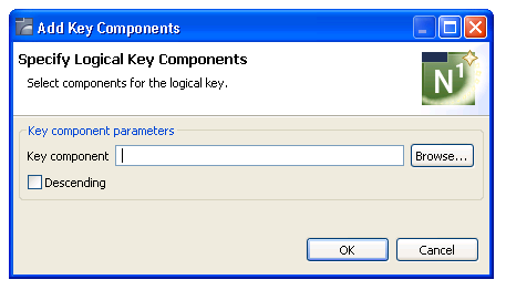
Define the following parameters for the key component:
| Parameter | Description |
|---|---|
| Key component | Type the name of the key
component in Key component or select
to display a list of components for selection.
For example:
You can specify either one superdescriptor or multiple individual descriptors. Note: |
| Descending | Indicates whether key
component values are listed in ascending or descending sequence in the
generated subprogram. To have the key component values listed in descending
sequence, select this parameter. Otherwise, values are sorted in ascending
sequence.
Note: |
Select to save the settings.
This section describes the specification parameters for the Object-Maint-Dialog wizard. This wizard generates a character-based user interface (Natural program) for an object-maintenance process. The dialog component communicates with the user and invokes methods (data actions) implemented by the object-maintenance subprogram. To generate a complete maintenance process using Natural Construct’s object-oriented approach, use this wizard in conjunction with the Object-Maint-Subp or Object-Maint-Enhanced-Subp wizard (which also generates the object PDA and restricted PDA).
This section covers the following topics:
Note:
For more information, refer to Object-Maint-Dialog
Model, Natural Construct Object
Models.
The Specify Standard Parameters panel is displayed when the wizard is invoked; it is similar for all Object-Maint wizards.
To specify standard parameters
Open the context menu in the Navigator view for the NaturalONE project in which you want to generate the modules.
Or:
Open the context menu in the
Navigator view for the library in which you want to
generate the modules.
Select .
The Specify Standard Parameters panel is displayed. For example:
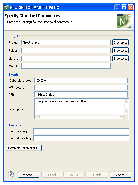
Many of the parameters on this panel are common to most wizards. For information, see Specify Standard Parameters. Optionally, you can:
| Task | Procedure |
|---|---|
| Define common parameters, such as support for direct command processing, message numbers, and password checking. | Select . For information, see Specify Common Parameters. |
Select .
The Specify Additional Parameters panel is displayed. For example:
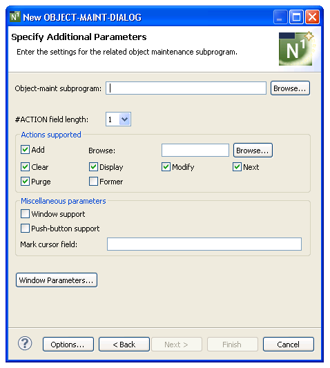
Use this panel to define parameters for the related object-maint subprogram and, optionally, to define screen parameters.
To specify additional parameters
Define the following parameters:
| Field | Description |
|---|---|
| Object maint subprogram | Name of the subprogram invoked by the generated dialog program. The specified subprogram must exist in the current library. Name of the object-maintenance subprogram used by the generated dialog program. Either type the name or select to display the available subprograms for selection. |
| #ACTION field length | Length of the action field.
By default, the length is "1" and all action fields
except Former are marked. If you do not want the generated dialog program to
perform a particular action, deselect the corresponding action field. At least
one action must be selected.
The available actions are:
Notes:
|
| Window support | Indicates whether the output from the generated object-maintenance dialog program is displayed in a window instead of on a panel. |
| Push button support | Indicates whether actions can be selected by cursor. |
| Mark cursor field | Name of the field on the map where the cursor is automatically placed by the generated dialog program. |
| Window Parameters | Change the default window parameters. For information, see Change the Window Settings. |
Select .
The Specify Input Map(s) for Horizontal Panel(s) panel is displayed. For example:

Use this panel to define horizontal panels and layout maps and, optionally, add scroll regions for the horizontal panels.
By default, the generated dialog program uses one panel and you must specify a layout map for that panel.
To specify the layout map for panel 1
Select the "1" row in Add Horizontal.
The and buttons are enabled.
Select .
The Define Horizontal Panel Details window is displayed. For information, see Define Horizontal Panel Details.
Note:
You can also use the Define Horizontal
Panel Details window to add additional horizontal panels. For
information, see Add a
Horizontal Panel.
Either type the name of the layout map in Map or select to display a list of available maps for selection.
The Specify Input Maps for Horizontal Panels panel is redisplayed, showing the name of the layout map in Input Map for panel 1.
Select .
The modules are generated using the current specifications. When generation is complete, the available user exits are displayed in the Outline view.
Save the generated modules.
At this point, you can:
Define user exits for the dialog program. For information, see Defining User Exits.
Use NaturalONE functionality to upload all generated modules to the server.
Optionally, you specify up to nine horizontal panels for the generated dialog (you must specify a minimum of one panel). If more than one panel is specified, the left and right PF-keys are activated in the generated program to allow left and right scrolling between panels.
This section covers the following topics:
To add a horizontal panel
Select on the Specify Input Maps for Horizontal Panels panel.
Define Horizontal Panel Details window is displayed. For example:
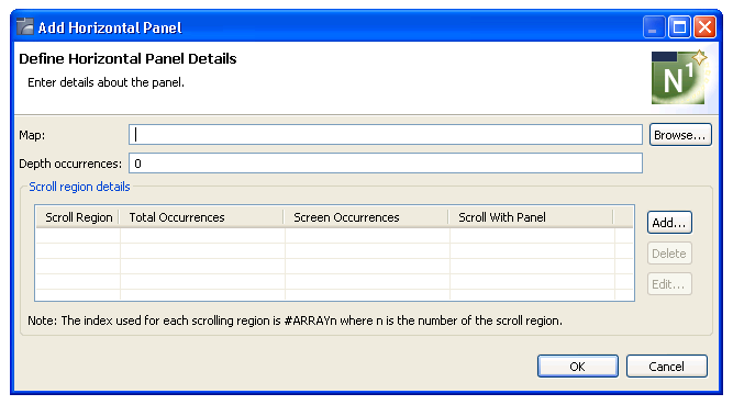
Define the following parameters for the horizontal panel:
| Field | Description |
|---|---|
| Map | Name of the layout map used for the corresponding panel. Either type the name of the layout map or select to display a list of available maps for selection. |
| Depth occurrences | To create a scroll region
with a third dimension, specify the maximum depth occurrences value. For
example, for a calendar with the months and days forming the first two
dimensions (horizontal and vertical) and the year forming the third dimension
(depth), you can specify "3" to scroll up to three
yearly tables of calendar months and days, and within each yearly table, scroll
vertically through the days.
The Depth occurrences value applies to the 3rd dimension on a panel, which means that it applies to all 3-dimension arrays on the map when using the #DEPTH index variable. To allow the value of the #DEPTH variable to be changed, you can either place the #NEXT-DEPTH (P3) variable on the specified map or use PF-keys that you process in the AFTER-INPUT user exit. |
| Scroll region details | Information for up to four vertical scroll regions for each horizontal panel. To define a scroll region, select . For information, see Define Scroll Region Details. |
Select to add the panel.
To delete a horizontal panel
Select the panel you want to delete on the Specify Input Maps for Horizontal Panels panel.
Select .
The panel is removed from the Scroll region details table.
To edit a horizontal panel
Select the panel you want to edit on the Specify Input Maps for Horizontal Panels panel.
Select .
Or:
Double-click on the row in the Scroll region
details table.
The Define Horizontal Panel Details window is displayed, showing the current settings for the panel.
Edit the panel settings.
Select to save the changes.
Optionally, you can define up to four vertical scroll regions (consisting of vertical arrays) for each horizontal panel. Scroll regions are only required for array fields. For example, assume you have an array field called #YEAR and each occurrence contains one month, but there is only enough space on the screen to display three months. In this case, a scroll region with a screen occurrences value of "3" is required.
In addition to scrolling through the months, you may also want to display the revenue for each month and have the revenue data change when the month changes. To do this, the starting index for #YEAR and #REVENUE must be the same. For example, assume the following:
#YEAR (A4/12)
#REVENUE (N5.1/12)
On the specified layout map, there should be three occurrences of both #YEAR and #REVENUE. For example, if these fields are in the first scroll region, use #ARRAY1 as the starting index for both fields. The object-maint dialog program will generate the appropriate code based on the values defined for the scroll region (for example, top left and bottom right). If the cursor is in the area defined by the upper left and bottom right coordinates, then #ARRAY1 will be incremented appropriately when the forward or backward PF-keys are selected.
Tip:
You can think of a two-dimensional (2D) array as a
collection of many one-dimensional (1D) arrays. And you can think of a fixed
instance of a third dimension of a three-dimensional (3D) array as a 2D array.
Therefore, a vertical scroll region on a generated panel can consist of 1D, 2D,
or 3D arrays.
This section covers the following topics:
Note:
If you add scroll regions, the specified map should
contain array fields that match the specified values.
To add a scroll region
Select on the Define Horizontal Panel Details panel.
Define Scroll Region Details window is displayed. For example:
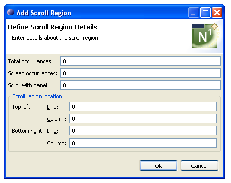
Define the following parameters for the scroll region:
| Field | Description |
|---|---|
| Total occurrences | Total number of scrollable
lines required for the scroll region. This value applies when the generated
dialog program includes a line scroll feature to scroll:
The generated program ensures that the values assigned to the array index values (#ARRAY1 through #ARRAY4) do not exceed the total occurrences value for each array. |
| Screen occurrences | Total number of lines displayed on the panel at one time (used when the Total occurrences value is specified). |
| Scroll with panel | Panel number to force a particular starting from value for a scroll region on a panel (so it has the same value as another panel). Each panel maintains its own current values for #ARRAYn, where n is 1, 2, 3, or 4. |
| Scroll region location
Top left |
Location of the top left
corner of the scroll region. A scroll region is always rectangular and is
defined by specifying the panel coordinates of the top left and bottom right
corners. Users can press the bkwrd and frwrd PF-keys to position the scroll
regions backward and forward.
The values for the top left corner are:
|
| Scroll region location
Bottom right |
Location of the bottom right
corner of the scroll region. These values are:
|
Select to add the scroll region.
To delete a scroll region
Select the scroll region you want to delete on the Define Horizontal Panel Details panel.
Select .
The scroll region is removed from the Scroll region details table.
To edit a scroll region
Select the scroll region you want to edit on the Define Horizontal Panel Details panel.
Select .
Or:
Double-click on the row in the Scroll region
details table.
The Define Scroll Region Details window is displayed, showing the current settings for the panel.
Edit the scroll region settings.
Select to save the changes.
This section describes the Object-Maint-Enhanced-Subp wizard, which generates an object-maintenance subprogram and corresponding PDAs. The generated subprogram updates all entities within an object and contains a full range of integrity checks (as defined by Predict relationships) and object semantics (in the form of Predict automatic rules or object manipulation within user exits). This wizard is similar to the Object-Maint-Subp wizard. The main difference between these wizards is that the Object-Maint-Enhanced-Subp wizard can generate large fields in the object PDA as dynamic fields. This allows long fields to occupy only the space required to pass the data to the database view. For example, one customer may require 1000 characters for delivery instructions and another customer only requires 50 characters. In the first case, 1000 characters will be placed in the parameter data area (PDA) and in the second case only 50 characters will be placed in the PDA.
The Object-Maint-Enhanced-Subp wizard allows you to take advantage of larger field sizes available in Natural and in the databases. In the past, an alphanumeric field in Natural was restricted to a length of 253 characters. To accommodate larger fields, you had to create an array of strings with a length of less than 254 characters each. This meant that words in a note, for example, may have been split across strings. Using this wizard, you can specify larger string sizes in the files and in Natural to allow the entire note to fit in one string. The wizard can also generate code to truncate trailing blanks, which can needlessly increase the amount of data going into the PDA, and generate an error message when a user enters data into a field that is longer than what the database expects.
This section covers the following topics:
Notes:
The Specify Standard Parameters panel is displayed when the wizard is invoked; it is similar for all Object-Maint wizards.
Note:
To access this wizard, the specified project must be mapped
to a version 8.2 or higher server environment.
To specify standard parameters
Open the context menu in the Navigator view for the NaturalONE project in which you want to generate the modules.
Or:
Open the context menu in the
Navigator view for the library in which you want to
generate the modules.
Select .
The Specify Standard Parameters panel is displayed. For example:
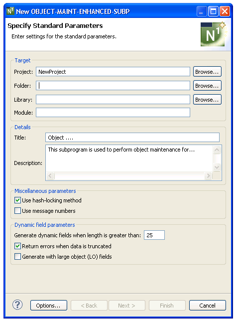
Many of the parameters on this panel are common to most wizards. For information, see Specify Standard Parameters. The Miscellaneous parameters are identical to those for the Object-Maint-Subp wizard. For information about these fields, see Object-Maint-Subp Wizard.
Optionally, you can:
| Task | Procedure |
|---|---|
| Generate dynamic fields into the object PDA when the size of the source field is larger than the number of characters specified in the Generate dynamic fields when length is greater than nnn field. | Select Generate
dynamic fields when length is greater than
nnn, where nnn
is a number less than 1000 and 0 indicates the data PDA contains the same
lengths as the DDM. For example, if the specified cutoff length is 50 and a
field is defined in the DDM as alphanumeric 100, an (A) DYNAMIC field will be
generated into the object PDA instead of an (A100).
Notes:
|
| Return an error message when the data in a dynamic field is larger than its source database field and the data will be truncated by the subprogram (i.e., dynamic fields in the PDA but not in the file view). | Select Return
errors when data is truncated to have the generated maintenance
subprogram return an error message when data is truncated.
For example, you may have a text field with a variable length for descriptive information that you want to set to 1000 characters. Since a dynamic field can handle more than 1000 characters, you must decide what happens if the user enters more. One option is to let the user enter whatever they want and the subprogram will truncate any data over the limit when it stores it in the database. Another option is to generate error messages when the user exceeds the limit and/or to stop the processing. When the subprogram is generated with the truncation option, Construct will provide error messages and a user exit to define how to handle the error. Within this user exit, Construct generates a list of all affected fields (i.e., are dynamic fields in the PDA but not in the file view) and allows you to change the value for ##RETURN-CODE or add an ESCAPE ROUTINE to continue with processing when an error occurs. Note: |
| Maintain large object (LO) fields with the generated maintenance subprogram. | Select Generate with large object (LO) fields. |
Select .
The Specify Additional Parameters panel is displayed. For example:
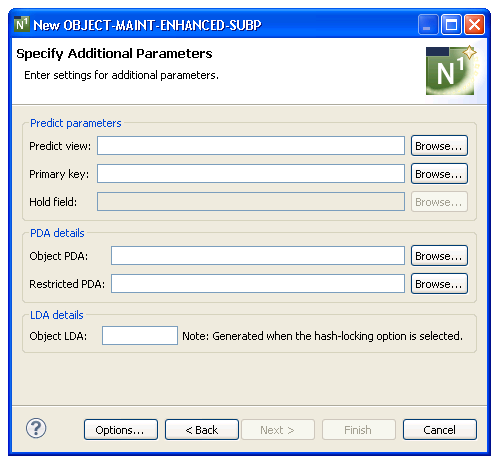
Use this panel to define additional parameters for your object-maint-enhanced subprogram.
The fields on this panel are identical to the fields on the Specify Additional Parameters panel for the Object-Maint-Subp wizard. The only difference is that the Generate options have been removed for the Object PDA and Restricted PDA fields. These parameter data areas will always be generated or regenerated with the Object-Maint-Enhanced-Subp wizard, since the field definitions may change when dynamic fields are processed.
To define additional parameters
Specify the additional parameters for the object-maint-enhanced subprogram.
For more information, see Specify Additional Parameters.
Select .
The Specify Input Parameters panel is displayed. For example:
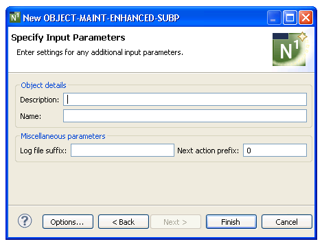
Use this panel to define additional input parameters for your object-maint-enhanced subprogram.
The fields on this panel are identical to the fields on the Specify Input Parameters panel for the Object-Maint-Subp wizard.
To define additional input parameters
Specify the additional input parameters for the object-maint-enhanced subprogram.
For more information, see Specify Input Parameters.
Select .
The modules are generated using the current specifications. When generation is complete, the available user exits are displayed in the Outline view.
Save the generated modules.
At this point, you can:
Use the NaturalONE Testing option to test the subprogram. For information, see Test a Subprogram Directly in Application Testing.
Define user exits for the subprogram. For information, see Defining User Exits.
Use NaturalONE functionality to upload all generated modules to the server.
This user exit can be used in the generated subprogram to define truncation routines and error messages for dynamic fields. It is a Conditional exit and available when the PDA for the subprogram contains dynamic fields in the object PDA that represent fixed-length fields in the database.
When you select the PROCESS-TRUNCATION-ROUTINE user exit, the following code is generated into the exit:
 Module ............. ModName
 Title .............. Object ....
 >                                              > + ABS: X X-Y: _ S    5 L    1
   All  ....+....1....+....2....+....3....+....4....+....5....+....6....+....7..
   0010 DEFINE EXIT PROCESS-TRUNCATION-ROUTINE
   0020 /* Start of PROCESS-TRUNCATION-ROUTINE user exit
   0030 /* note that the ##RETURN-CODE can be changed or
   0040 /* ESCAPE ROUTINE can be added so that one doesn't stop the program.
   0050 END-EXIT
To allow processing to continue when a truncation error occurs, you can change the value for ##RETURN-CODE or add an ESCAPE ROUTINE.
This section describes the Object-Maint-Subp wizard, which generates a subprogram that maintains complex data objects. The subprogram updates all entities within an object and contains a full range of integrity checks (as defined by Predict relationships) and object semantics (in the form of Predict automatic rules or object manipulation within user exits).
This section covers the following topics:
Notes:
The Specify Standard Parameters panel is displayed when the wizard is invoked; it is similar for all Object-Maint wizards.
To specify standard parameters
Open the context menu in the Navigator view for the NaturalONE project in which you want to generate the modules.
Or:
Open the context menu in the
Navigator view for the library in which you want to
generate the modules.
Select .
The Specify Standard Parameters panel is displayed. For example:
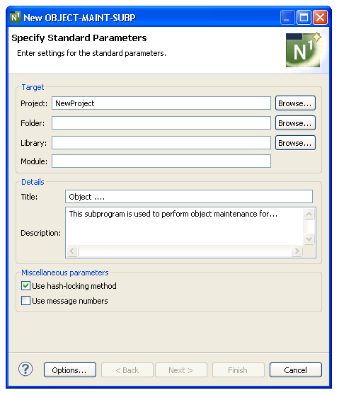
Many of the parameters on this panel are common to most wizards. For information, see Specify Standard Parameters. Optionally, you can:
| Task | Procedure |
|---|---|
| Use the hash-locking method of optimistic record locking (instead of the timestamp method). | Select Use hash-locking method. When this method is selected, the Hold field parameter is disabled on the second specification panel and the Object LDA parameter is enabled. To enable the Hold field, deselect Use hash-locking method. |
| Use message numbers for all REINPUT and INPUT messages (instead of message text). | Select Use message
numbers. When this option is selected, message numbers rather than
message text will be used for all REINPUT and INPUT messages.
Note: |
Select .
The Specify Additional Parameters panel is displayed. For example:
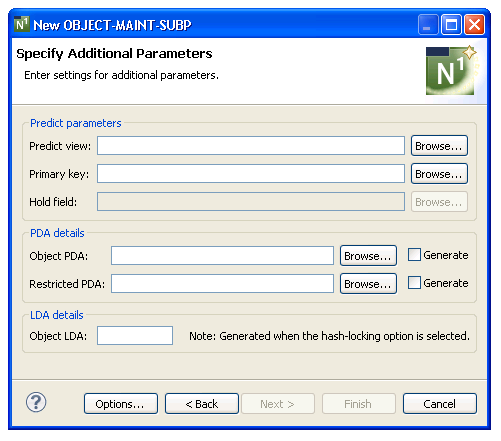
Use this panel to define additional parameters for your object-maintenance subprogram.
To specify additional parameters
Define the following parameters:
| Parameter | Description |
|---|---|
| Predict view | Name of the Predict view used by the generated subprogram. The view must be defined in Predict. Either type the name or select to display the available views for selection. |
| Primary key | Name of the key in
Predict for the primary file. This key becomes the
primary key to access the view for maintenance. The key can be a descriptor,
superdescriptor, or subdescriptor. If the key does not exist in the specified
Predict file, an error message is displayed.
Note: |
| Hold field | Name of the field used to
logically protect the record against intervening update or delete actions.
Because an object-maintenance subprogram does not use the record-holding
facilities of the DBMS to lock records during a GET operation, a hold
field must exist in the primary file for the object. Valid data types are:
Note: |
| Object PDA | Name of the object parameter
data area (PDA) that defines the rows returned to the object-maint subprogram
and the columns within each row. Either type the name or select
to display the available PDAs for selection.
Alternatively, you can select Generate to have the data
area generated by the wizard.
The generated object PDA contains one column for each field defined in the specified Predict view (as well as additional columns). You can remove any fields that are not components of the primary key. Note: |
| Restricted PDA | Name of the restricted PDA
that stores data, such as the last sort key, the last starting value, the last
row returned, etc. so that the next set of consecutive records is returned to
the caller. Either type the name or select to
display the available PDAs for selection. Alternatively, you can select
Generate to have the data area generated by the wizard.
Notes:
|
| Generate | Indicates whether an existing object PDA or restricted PDA is regenerated. Regeneration is required when fields have changed in the file. If the PDAs do not exist, they will be automatically generated by the wizard. |
| Object LDA | Name of the object local data
area generated for the object-maintenance subprogram.
Note: |
Select .
The Specify Input Parameters panel is displayed. For example:
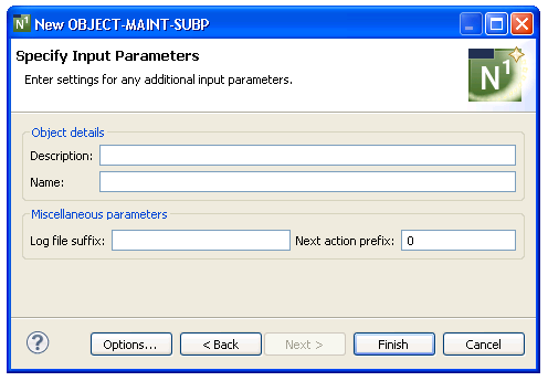
Use this panel to define additional input parameters for your object-maintenance subprogram.
To specify input parameters
Define the following parameters:
| Parameter | Description |
|---|---|
| Description | Object description used in messages. If you specify "Person", for example, messages are displayed as "Person not found" and "Person displayed". |
| Name | Name of the level 1 structure
used to qualify the fields in the object PDA. (It is easier to identify the
source of these attributes when the PDA name is used for this purpose.) The
object name should be kept to a reasonable length.
Note: |
| Log file suffix | If you want to log objects,
you have to create a log file corresponding to each entity within the object.
The name of the log file is the name of the object file concatenated with the
suffix specified here. For example, if the object consists of the
NCST-ORDER-HEADER and NCST-ORDER-LINES entities and you specify
"-LOG", the log file names are NCST-ORDER-HEADER-LOG
and NCST-ORDER-LINES-LOG.
The following fields are required in the log file that corresponds to the header entity in the object:
In the log files corresponding to the sub-entities in the object, only the LOG-ACTION field is required. Note: |
| Next action prefix | If the primary key is
compound or redefined into various components, supply a value to limit the
number of prefixed components confined on the Next action. This allows the
subprogram to maintain objects with a common prefix value.
For example, if the primary key is made up of Company + Account + Division and you do not want the Next action to span the Division values, specify "2". Specify "1" if the Next action is to be limited to the current Company value. |
Select .
The modules are generated using the current specifications. When generation is complete, the available user exits are displayed in the Outline view.
Save the generated modules.
At this point, you can:
Use the NaturalONE Testing option to test the subprogram. For information, see Test a Subprogram Directly in Application Testing.
Define user exits for the subprogram. For information, see Defining User Exits.
Use NaturalONE functionality to upload all generated modules to the server.
This section describes the specification parameters for the Quit wizard. This wizard generates a quit program that releases resources used by an application. It displays a confirmation window that overlays the host panel and gives users the option of quitting an application entirely or resuming where they left off. The name of the quit program is assigned to the DIALOG-INFO.##QUIT global variable in a Natural Construct-generated startup program.
This section describes the Specify Standard Parameters panel for the Quit wizard. This panel is the only specification panel for the wizard.
To specify standard parameters
Open the context menu in the Navigator view for the NaturalONE project in which you want to generate the modules.
Or:
Open the context menu in the
Navigator view for the library in which you want to
generate the modules.
Select .
The Specify Standard Parameters panel is displayed. For example:
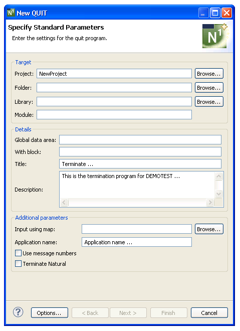
Many of the parameters on this panel are common to most wizards. For information, see Specify Standard Parameters. Optionally, you can use this panel to:
| Task | Procedure |
|---|---|
| Provide the name of the layout map used for the generated quit program. | Type the name of the map in Input using map or select to display the available maps for selection. |
| Provide a name for the application that will be used in confirmation messages. | Type the name in Application name. |
| Use message numbers for all REINPUT and INPUT messages. | Select Use message
numbers. When this option is selected, message numbers rather than
message text will be used for all REINPUT and INPUT messages.
Note: |
| Have the quit program issue a Natural terminate command. | Select Terminate
Natural. By default, the generated quit program:
|
Select .
The quit program is generated using the current specifications. When generation is complete, the available user exits are displayed in the Outline view.
Save the generated module.
At this point, you can:
Define user exits for the quit program. For information, see Defining User Exits.
Use NaturalONE functionality to upload all generated modules to the server.
This section describes the specification parameters for the Startup wizard, which generates a startup program for an application. These programs (often named Menu) initialize global variables and invoke the main menu program.
This section covers the following topics:
This section describes the Specify Standard Parameters panel for the Startup wizard. This panel is the only specification panel for the wizard.
To specify standard parameters
Open the context menu in the Navigator view for the NaturalONE project in which you want to generate the modules.
Or:
Open the context menu in the
Navigator view for the library in which you want to
generate the modules.
Select .
The Specify Standard Parameters panel is displayed. For example:
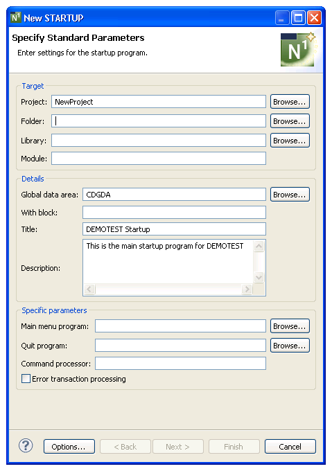
Many of the parameters on this panel are common to most wizards. For information, see Specify Standard Parameters.
Define the following parameters:
| Parameter | Description |
|---|---|
| Main menu program | Name of the program invoked by the startup program. This is usually the first panel displayed when a user issues the Natural MENU command. |
| Quit program | Name of the program invoked
when a user ends a session.
Tip: |
Optionally, you can:
| Task | Procedure |
|---|---|
| Provide the name of a Natural command processor to process commands entered on the direct command line. | Type the name in Command processor. The specified command processor must have been created using the Natural SYSNCP systems utility. |
| Assign Natural Construct’s default error transaction program (CDERRTA) to the *ERRORTA system variable. | Select Error transaction processing. For information about *ERRORTA, see the Natural documentation. |
Select .
The startup program is generated using the current specifications. When generation is complete, the available user exits are displayed in the Outline view.
Save the generated module.
At this point, you can:
Define user exits for the startup program. For information, see Defining User Exits.
Use NaturalONE functionality to upload all generated modules to the server.
This section describes the Specify the Dynamic Attribute Parameters window, which allows you to define up to four attributes, one of which must be the return to default display attribute (Default return field).
Notes:
To change the dynamic attribute characters
Select .
The Specify the Dynamic Attribute Parameters window is displayed. For example:
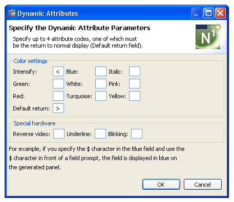
Define up to four dynamic attributes, one of which must be the return to default display attribute (Default return field).
Select to save the settings.
This section describes the Specify Window Parameters window, which defines window parameters such as the height, width and position of the generated window, as well as whether it has a frame or not.
To change the window settings
Select .
The Specify Window Parameters window is displayed. For example:
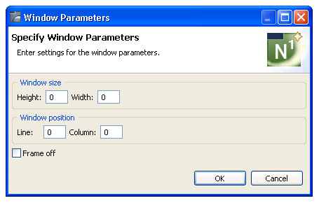
Define the following parameters:
| Parameter | Description |
|---|---|
| Height | Number of lines the window will span. |
| Width | Number of columns the window will span. |
| Line | Number of lines from the top of the panel to the top of the window. |
| Column | Number of columns from the left side of the panel to the left side of the window. The line and column values form the top left corner of the window. |
| Frame off | Determines whether the window is displayed with or without a border. Select this option to display the window without a border (frame). |
| Title | Title used for the window. |
Select to save the settings.
This section describes the Select Message Number window, which displays the available SYSERR numbers for selection.
To select a SYSERR number
Select for Prompt on the Specify Additional Parameters panel.
The Select Message Number window is displayed. For example:
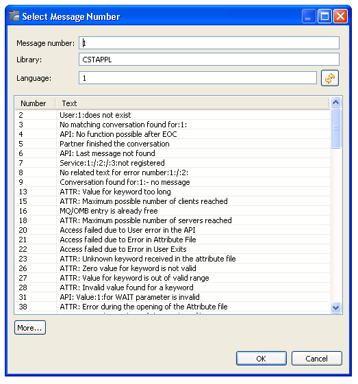
This window displays the available SYSERR numbers for selection.
Define the following parameters:
| Parameter | Description |
|---|---|
| Message number | Number of the SYSERR listing in
the specified library (by default, "1"). To display
a different SYSERR listing, type a new number and select
|
| Library | Name of the library containing
the SYSERR numbers (by default, "CSTAPPL"). To
change the library, type a new library name and select
|
| Language | Code for the language number
(by default, "1" for English). To change the
language, type a new language code and select
|
| More | Displays additional SYSERR numbers (when more than 100 numbers are available). To display the next 100 SYSERR numbers, select . Once all numbers have been displayed, the button is disabled. |
Select the SYSERR number you want to use in the table.
Select .
This section describes the Specify Common Parameters window, which defines common parameters such as support for direct command processing, message numbers, or password checking.
To define common parameters
Select .
The Specify Common Parameters window is displayed. For example:
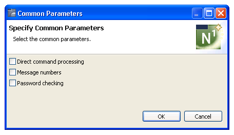
Select one or more of the following options:
| Option | Description |
|---|---|
| Direct command processing | Select this option to enable direct command processing. |
| Message numbers | Select this option to use
message numbers rather than message text for all REINPUT and INPUT messages.
Note: |
| Password checking | Select this option to enable password checking. To include password checking, you must also set up a password file. For information, see Set Up a Password File. |
Select to save the settings.
You can specify password checking for many of the generated modules. Natural Construct builds the mechanism for password checking into your modules by including the CCPASSW copycode member. Within this copycode, the CDPASSW subprogram is invoked and passed the module and library names.
To include password checking, you must set up a password file. The file is keyed on the module name used to catalog the module and the library name used to generate the module.
The password file can be a view of any file with Natural-Construct-Password as the data definition module (DDM) name. The view must contain the following fields:
| Field | Format |
|---|---|
| PASSWORD-KEY | A40 (32-character library name, plus an 8-character module name) |
| PASSWORD | A8 (8-character password) |
When a user attempts to invoke the module, the CDPASSW subprogram reads the password file. If the module/library name combination exists in the file and does not have a password, the user can invoke the module. If the module/library name combination exists and has a password, the user must enter the correct password before the module is invoked. If a user enters five incorrect passwords, execution is aborted.
If you specify password checking, you must modify the CDPASSW subprogram to include a valid password view and any final processing you want to perform and then catalog the modified subprogram. For more specific password checking, you can modify the CCPASSW copycode member (to call a different subprogram) or modify the CDPASSW subprogram (to refine your security standards).
This section describes the Specify International Parameters window, which defines the language used to display text on generated panels. You can define international parameters for modules generated using the Object-Browse-Dialog and user exit models.
To specify international parameters
Select .
The Specify International Parameters window is displayed. For example:
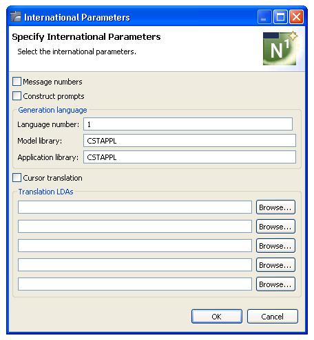
Define the following parameters:
| Parameter | Description |
|---|---|
| Message numbers | Type of messages used. When this option is selected, the generated code uses message numbers rather than message text. |
| Construct prompts | Type of prompts used. When this option is selected, the model generates Natural Construct-style prompts (for example, 1 of 2). |
| Language number | Code for the language used when generating message text. The default is 1 (English). |
| Model library | Name of the SYSERR message library used to retrieve common message text. The default is CSTAPPL. |
| Application library | Name of the SYSERR library used to retrieve message text for user-defined SYSERR references. This parameter is only applicable to modules generated using the Object-Browse-Dialog wizard. If you do not specify an application library, the Model library value is used. |
| Cursor translation | When this option is selected, the generated code supports cursor-sensitive translation (users can modify or translate panel text dynamically in translation mode). |
| Translation LDAs | Names of the translation local data areas (LDAs) used by generated modules. You can specify up to five translation LDAs. Either type the name or select to display the available data areas for selection. |
Select to save the settings.
This section describes the Specify Screen Parameters window, which defines how information is displayed on the generated screen.
To specify screen parameters
Select .
The Specify Screen Parameters window is displayed. For example:
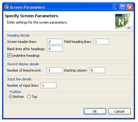
Define the following parameters:
| Parameter | Description |
|---|---|
| Screen header lines | Number of screen heading lines displayed on the generated screen (by default, two panels). |
| Field heading lines | Number of field heading lines displayed on the generated screen (by default, one line is reserved for each field heading line). |
| Blank lines after headings | Number of blank lines inserted after the field heading lines. For example, if you specify "1", one blank line is inserted below each field heading line. |
| Underline headings | Indicates whether field headings are underlined. By default, this option is marked and field headings are underlined on the generated screen. |
| Number of lines/record | Number of screen lines required to display each record and its attributes (by default, one line is reserved for each record). |
| Starting column | Number of the screen column in which the selection column begins. |
| Number of input lines | Number of screen lines required to display the input keys (by default, one line is reserved for each input key). |
| Position Bottom | Indicates whether the input key lines are displayed at the bottom of the generated screen (by default, this option is selected and the input key lines are displayed at the bottom). |
| Position Top | Indicates whether the input key lines are displayed at the top of the generated screen. To have the input key lines displayed at the top of the screen, select this option. |
Select to save the settings.
The Specify Standard Parameters panel is displayed when a wizard is invoked; it is similar for all wizards. This section describes parameters on this panel that are common to multiple wizards. For information about parameters that are specific to individual wizards, see the applicable wizard section.
To specify standard parameters
Open the context menu in the Navigator view for the NaturalONE project in which you want to generate the modules.
Or:
Open the context menu in the
Navigator view for the library in which you want to
generate the modules.
Select .
The Specify Standard Parameters panel for the selected wizard is displayed. The following example shows the panel for the Browse-Select wizard:
Define the following parameters:
| Parameter | Description |
|---|---|
| Library | Name of the library in which to store the generated modules. Either type the name or select to display the available libraries for selection. |
| Module | Name of the module to be generated. This name must follow standard Natural naming conventions. |
| Global data area | Name of the global data area (GDA) used by the module to be generated. To allow inter-program communication, generated modules require a small number of global variables. The supplied CDGDA global data area contains the global variables required to test a generated module. Before creating a new application, copy this GDA from the SYSTEM library and rename it to match your naming conventions. Then add any additional global variables your application may require. |
| Title | Title for the module to be generated. You can customize the title for your application. |
| Description | Brief description of what the generated module will do. This field is used internally for documentation purposes. |
| First heading | First heading displayed on the generated panel. This heading is centered at the top of the generated panel and intensified. |
Optionally, you can:
| Task | Procedure |
|---|---|
| Define a different NaturalONE project in which to generate the module(s). | Type the name of the project in Project or select to display a window listing the existing projects for selection. The project must currently exist. |
| Define a folder in which to generate the module(s). | Type the name of the folder in
Folder or select to display
a window listing the existing folders for selection. The folder must currently
exist within the selected NaturalONE project.
Note: |
| Define a GDA block for use with the specified GDA. | Type the name of the GDA block in With block. You need only specify the lowest level block name; the corresponding path name is determined automatically. For more information about GDA blocks, see the Natural documentation. |
| Define a second heading for display on the generated panel(s). | Type the heading in Second heading. This heading is centered under the first heading and intensified. |
| Select generation options for the module(s). | Select . For information, see Generation Options. |
Select .
The next panel for the specified wizard is displayed. For information, see the applicable wizard section.
This section provides an example of using the QUIT wizard to generate a quit program.
To generate a quit program
Open the context menu in the Navigator view for the NaturalONE project into which you want to generate the quit program.
Or:
Open the context menu in the Navigator
view for the library into which you want to generate the quit program.
Select .
First the Progress Information window is displayed, showing progress as the model specifications are initialized, and then the wizard panel is displayed. For example:
The names of the project and library from which this panel was invoked are displayed (you can change these if desired).
Type "MYQUIT" in Module.
Type "CDGDA" in Global data area.
The CDGDA global data area contains the global variables required to test a generated module.
Select Finish.
The generation progress is displayed at the bottom of the panel. For example:
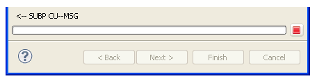
When generation is complete, the quit program is displayed in the Navigator view. For example:
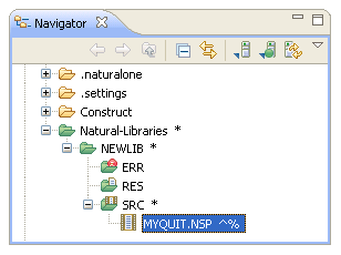
The quit program is also displayed in the editor. For example:
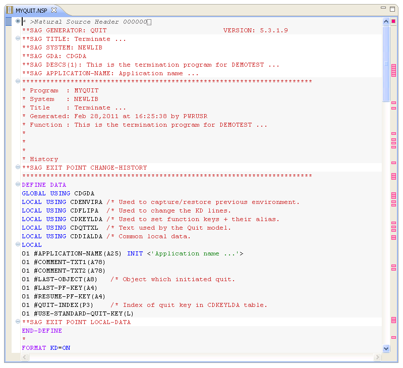
At this point, you can define additional processing within user exits. User exit code is preserved during regeneration. For information, see Defining User Exits.
You can regenerate any module that was generated using a Natural Construct or client generation wizard. You can also select more than one project, folder, or object to regenerate multiple modules. When regenerating multiple modules, a selection window is first displayed to select the resources to be regenerated.
To regenerate Natural Construct-generated modules
Open the context menu for one or more projects, folders, or modules in the Navigator view.
You can use standard selection techniques.
Select .
The model PDA is uploaded to the mainframe to be populated and then downloaded to the local Eclipse environment to populate the PDA values before displaying the first wizard specification panel. You can then edit the specifications and select .
Or:
Select .
A progress window is displayed as the wizard locates and loads the regeneratable resources. Next, a selection window is displayed to choose the resources you want to regenerate. For example:
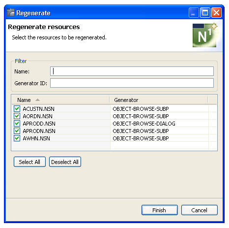
Using this panel, you can:
| Task | Procedure |
|---|---|
| Filter the list of resources for selection. | Type a prefix in Filter. For example, if you type "AP", only the resources beginning with AP are selected. |
| Use a different code generator to regenerate the resource. | Type the generator ID in Generator ID. |
| Deselect all resources. | Select Deselect All. |
After selecting the resources, select . The modules are generated without displaying the wizard panels.
When regenerating a resource that was generated using a Natural Construct client generation wizard, the following process occurs:
The original generated source code is uploaded to the Natural server.
This allows the **SAG lines to be parsed into the
model PDA (and user exits to be processed later).
The Read program is executed to populate the model PDA.
The generation process begins, using the downloaded model PDA data.
User exits are merged on the server.
All generated modules are downloaded from the server to the client.