
As a system administrator, you can set system-wide defaults for various objects and functions.
This section covers the following topics:
This section covers the following topics:
 To modify the system defaults:
Select the System Administration > Defaults > System node in the object workspace.
Invoke the context menu and choose .
The System Defaults are displayed, and you can change them. The fields are described under Components of System Defaults.
Choose to save your changes.
To display the system defaults:
Select the System Administration > Defaults > System node in the object workspace.
Invoke the context menu and choose .
The System Defaults are displayed. The fields are described under Components of System Defaults.
Select to close the window.
| Field | Explanation | |||
|---|---|---|---|---|
| NOM definition-data file (DBID/FNR) | The Adabas database ID and file number of the Entire Output Management definition-data file (logical file 206). | |||
| NOM active-data file (DBID/FNR) | The Adabas database ID and file number of the Entire Output Management active-data file (logical file 91). | |||
| NOM trigger container file | See Trigger Container File. | |||
| Use owner ID |
If selected: Operating-system resources should be accessed with the user ID of the report owner or bundle coordinator. This allows users whose ID is not defined externally (RACF, BS2000 user ID, etc.) to use Entire Output Management. If not selected: The Entire Output Management user must have authorization to access operating-system resources. |
|||
|
Use Owner ID
|
User ID is ESY
User
|
Browse
|
Submit Job
|
|
| Selected | Yes | Report Owner | User ID | |
| No | Report Owner | |||
| Not selected | Yes | User ID | User ID | |
| No | - | Monitor | ||
| Support long names |
|
|||
| Date format | Select the format to be
used for date information in Entire Output Management:
|
|||
| Automatic user definition |
|
|||
| Daily cleanup |
Once a day, cleanup processing is performed which deletes: active reports (or marks them for archiving), expired active reports from archive/revival, log records, printout records, and active bundles. If you run the monitor as a single task, it will be
unable to process any reports, bundles or printouts while performing daily
cleanup. To avoid this, you can define multiple tasks (daily cleanup is done by
task 1) or execute the daily, report and spool cleanup as a stand-alone batch
job. To achieve the latter, execute the program Time = The time when you want to execute the cleanup process. Next run = The date and time of the next cleanup run. |
|||
See Integrating Natural Applications below.
| Field | Explanation | |
|---|---|---|
| Log | ||
| Types |
Select the types of information to be logged. You can log maintenance information for reports, bundles, logical printers, distribution lists, and information about logon/logoff activities of users. |
|
| Retention |
Enter the default retention period for log records. This is the period of time that log records are kept in the Entire Output Management database. You set this period by specifying a number and a unit of time (days, weeks or months). |
|
| Printouts | ||
| Types |
Specify the type(s) of printouts to be deleted automatically at the end of the printout Retention period:
|
|
| Retention |
Specify the default retention period for printouts. This is the period of time that printouts are kept in the Entire Output Management database. You set this period by specifying a number and a unit of time (days, weeks or months). |
|
| Type: Print on hold |
Specify the default retention period for held printouts. This is the period of time that printouts in Hold status are kept in the Entire Output Management database. You set this period by specifying a number and a unit of time (days, weeks or months). |
|
These settings apply to the expansion of the treeview. If a treeview node is expanded and the number of records to be listed is very large, the expansion may take very long. In this case, you can expand a treeview node not all at once but in intervals (portions). This form of treeview expansion is controlled by the following fields.
| Field | Explanation | |
|---|---|---|
| Use standard interval settings for all users |
If selected, these settings apply to all users and cannot be changed by a user individually. If not selected, every user can set his/her own treeview intervals (via Options in the Menu Bar). |
|
|
Use intervals to display large amounts of
data:
If selected, intervals are used for treeview expansion; if not selected, intervals are not used. If intervals are used, they are controlled by the following options:
|
||
| Use standard timeout settings for all users |
If selected, the timeout setting specified in the field below applies to all users and cannot be changed by a user individually. If not selected, every user can set his/her own timeout interval (via Options in the Menu Bar).
|
|
| Perform search in advance when opening the search dialog |
This option applies to the search for active reports in a folder. If this option is not selected, the Search dialog initially displays an empty result list. This prevents a search with unknown search criteria, as this might cause a system time-out in environments with a large number of active reports. If this option is selected, the Search dialog initially displays the result list of active reports based on the current search criteria. |
|
You can specify Natural applications which are to be displayed on the Main Menu of Entire Output Management, from where the users can invoke them (not available in the Output Management GUI client).
To integrate applications in the Main Menu:
In the Applications section of the System Defaults window, you specify each application as follows:
| Field | Explanation |
|---|---|
| Title | The text which is to be displayed on the Main Menu. |
| Library | The Natural library in which the application is contained. |
| Program | The name of the Natural program which is to be executed as startup transaction. |
| Parameters | The application-specific startup parameters. |
The defined applications are displayed for all users on the Main Menu of Entire Output Management. Under Natural Security, only users with the appropriate access rights will be able to log on to an application.
To return from an application to the Entire Output Management
Main Menu, the application must finish with
RETURN.
If Entire Operations, Entire Event Management or Natural NSPF are installed at your site, these products are automatically displayed on the Main Menu of Entire Output Management. In this way, it is easy for users to "toggle" between them and Entire Output Management.
Under Natural Security, only users with the appropriate access rights will be able to log on to a product.
This section covers the following topics:
The Monitor runs as one or more subtasks under Entire System Server or as one or more batch jobs and controls the generation, printing and distribution of reports and bundles.
Before you specify several Monitor tasks or allow several Natural
tasks, you should check the value of NATNUMSUB in the Entire
System Server startup parameters:
NATNUMSUB=subtask-maximum
subtask-maximum is the
maximum number of subtasks (recommended: 20).
In z/OS and z/VSE, subtasks run under the Monitor Entire System Server node. In BS2000, one batch job is run for each Monitor task. In UNIX, each Monitor task uses a separate process.
To modify the monitor defaults:
Select the System Administration > Defaults > Monitor node in the object workspace.
Invoke the context menu and choose .
The Monitor Defaults are displayed, and you can change them.
The fields available vary depending on the spool type. They are described under Components of Monitor Defaults.
When you have made you changes, choose to save them.
To display the monitor defaults:
Select the System Administration > Defaults > Monitor node in the object workspace.
Invoke the context menu and choose .
The monitor defaults are displayed. The fields are described under Components of Monitor Defaults.
Select to close the window.
| Field | Explanation | |
|---|---|---|
| Node | Displays the name/number of the Entire System Server node under which the Entire Output Management Monitor is run as a subtask or batch job. | |
| System | Displays the system type (e.g. z/OS, z/VSE). | |
| Spool type | Displays the spool type (POWER, JES2, JES3, SPOOL/BS2000 or UNIX). | |
| Batch module |
This field is only available for POWER/JES2 and JES3. Enter the name of the Natural batch module to be used by the Monitor. The module must reside in the Entire System Server load library or in one of the Entire System Server steplib libraries defined for the Natural task that is started. For information on creating the batch module, see the Installation and Customization documentation. |
|
| System server job name |
This field is only available for POWER/JES2 and JES3. Enter the name of the Entire System Server job. |
|
|
The number of tasks attached to print reports and bundles (maximum 32). See also the recommendations under Monitor Tasks. |
||
| Wait factor | These fields are used to adjust monitoring to the load in your installation. It is the time in seconds the Monitor waits between two consecutive monitoring cycles. During each cycle, the Monitor performs all the work accumulated since the end of the last cycle. | |
| Minimum | Enter the minimum time in seconds the Monitor is to wait between two consecutive monitoring cycles. | |
| Maximum | Enter the maximum time in seconds the Monitor is to wait between two consecutive monitoring cycles. | |
| Increment | If there is no activity during the minimum wait time, the wait time is increased by the value you enter here, until the maximum is reached. When activity occurs, the wait time returns to the minimum. Enter the number of seconds by which the wait time should increase. | |
| Error handling | Retries | The number of retries for a failed Monitor operation. The action in error will not cause an error message, but it will be tried again after the time specified in the Interval field. |
| Interval | The time in seconds after which a failed Monitor operation is tried again. | |
| Emergency emails | You can specify one or more email addresses. In the case of severe errors, the Monitor will send error information to these addresses. See Email Message Definitions for details. | |
| Jobcards |
Enter a job card to be used as a default when no other job card is specified. The following substitution variable can be used:
Trace:
Tracing requires a huge amount of database space and deteriorates performance considerably; therefore, the trace function should only be used if requested by Software AG Support. If the text In addition, the Monitor trace switches on the tracing facilities of Entire System Server and the Natural Data Collection trace function if required by the specified program level.
Note: |
|
| Field | Explanation | |
|---|---|---|
| SPOOL/BS2000 | ||
| Rename files |
Select this option to rename files, or deselect it to not rename them. Entire Output Management renames the print files during processing by adding an internal ID to make them unique. If renaming is deactivated, the option Copy files (see below) must be selected to copy the source to a container file. To avoid inconsistencies with reports resulting from BS2000 input files with changing contents, they should be stored in the NOM database; that is, the reports should be defined with the general attribute Copy report content to NOM database. |
|
| Copy files |
Select this option to copy BS2000 files to an Entire Output Management container file; or deselect it to not copy them. At least one destination has to be defined; see Container Files below. When this option is active, the original BS2000 files will not be processed by Entire Output Management after being copied, in particular cleanup processing will not delete them. |
|
| Virtual printer |
Enter the names of virtual printers (RSO) defined in BS2000. The printouts for this device are processed by Entire Output Management. (The printers must be virtual and must not be enabled for the spooling system). If the type of carriage control is not contained in the RECFORM attribute, the printout must be routed to the printer assigned to the corresponding carriage control. As of BS2000 spool version 3.0 B, exactly one virtual
printer (not RSO), which can be addressed with the
|
|
| POWER/JES2 and JES3 | ||
| These fíelds are used to define the SYSOUT classes dedicated to Entire Output Management. | ||
| Execution (JES3 only) |
Enter a list of execution classes to be processed by Entire Output Management. This method creates considerable performance overhead and should only be used for compatibility reasons. In future, only SYSOUT classes should be used for processing by Entire Output Management. If, however, you still need this method during a transitional period: in addition to searching SYSOUT classes for output, execution classes can also be searched. In this case, the following limitations apply:
|
|
| Sysout | Enter a list of SYSOUT classes to be processed by Entire Output Management. Only those jobs with SYSOUT files in these classes are processed. | |
| Internal | Define one SYSOUT class to hold temporary SYSOUT files. This class must not be one of the classes defined in the Sysout field above. | |
| Enter the class in which reports and bundles are to be printed. | ||
| Error | Define one SYSOUT class to hold the SYSOUT files which cause an error during processing. This class must not be one of the classes defined in the Sysout field above. | |
For information on the use of container files, see Container Files and Active-Data File in the Concepts and Facilities documentation.
To define a container file for the Monitor:
On the Monitor Defaults screen, select .
A window is displayed, in which you specify:
| Field | Explanation | |
|---|---|---|
| Destination | The destination of the
container file, as specified in the DEST=(,...) parameter of the
$$LST (POWER) or of the DD statement (JES).
|
|
| DBID / FNR | The database ID and file number of the container file. | |
This function is used to define subtask processing for the Entire Output Management Monitor.
You can split the workload of the Monitor between different tasks, each with its own wait factors.
The management functions of the Monitor (for example, cleanup, active bundle flushing) are always performed by Task 1. In addition, Task 1 will take over the work for any other task that fails.
To define subtasks:
In the Monitor Defaults window, select .
The list of tasks is displayed:
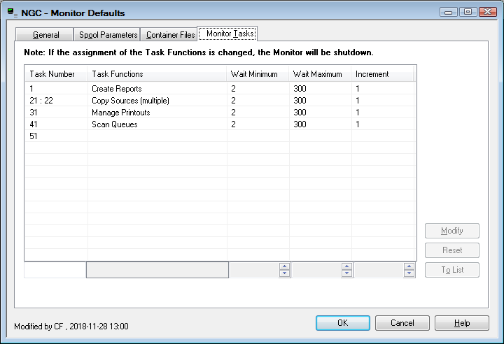
Make the task specifications as desired.
If you change the assignment of the task functions, the Monitor will be shut down.
The number of additional Monitor tasks depends on your execution environment. The following table gives some recommendations:
| Environment | Total Number of Monitor Tasks | Additional Tasks for Functions | Wait Factors (in seconds) | Number of Printer Tasks | |||
|---|---|---|---|---|---|---|---|
| Minimum | Maximum | Increment | |||||
| General recommendation | 2 | Manage Printouts/Special | 5 | 30 | 1 | 2 | |
| Many short printouts | 2 | Manage Printouts/Special | 1 | 20 | 1 | 4 - 10 | |
| Few large printouts | 3 | Manage Printouts/Special, Copy Sources | 10 | 30 | 1 | 2 - 4 | |
| Many short printouts plus a few large printouts | 3 | Manage Printouts/Special, Copy Sources | 1 | 20 | 1 | 4 - 10 | |
In a multi-node environment, the workload of copying sources may be too great for a single task to handle. In this case, you can split this workload between up to 9 tasks.
If the copying of sources is handled by multiple tasks, each of the tasks dedicated to copying sources cannot perform any other function.
To define multiple tasks for copying sources:
In the Monitor Task Profile window, select as task function .
Next to it, specify the number of tasks for copying sources.
You can define default parameters for report processing. These defaults apply to newly-created reports and can be modified for each report.
This section covers the following topics:
To modify the report defaults:
Select the System Administration > Defaults > Report node in the object workspace.
Invoke the context menu and choose .
The Report Processing Defaults are displayed, and you can change them.
The fields are described under Components of Report Defaults.
The Action options correspond to those described in the General Attributes of a report.
Choose to save your changes.
To display the report defaults:
Select the System Administration > Defaults > Report node in the object workspace.
Invoke the context menu and choose .
The Report Processing Defaults are displayed.
The fields are described under Components of Report Defaults.
The Action options correspond to those described in the General Attributes of a report.
Select to close the window.
| Field | Explanation | ||
|---|---|---|---|
| Report Retention | These fields determine
how long reports are stored in the Entire Output Management database. When this
retention period expires, the reports are purged and/or archived, depending on
the selected Action.
The default retention period is the system-wide period defined by the system administrator. |
||
| Action |
Possible actions:
When an active report is archived, its content is no longer available online. After this, it only exists in the archive data set and has to be revived before it can be viewed or printed again. |
||
| Number | Specify the number of days/weeks/months the report is to be stored in the Entire Output Management database. | ||
| Unit |
Possible values:
If you select "working days", you have to specify a calendar which distinguishes between working and non-working days. |
||
| Calendar | If you specify "working days" as the Unit of time, you have to specify the name of the calendar which determines which days are considered to be working days. See also Calendars. | ||
Example: If you want
reports to be kept for two working days, you specify Number 2 and
Unit working days. Assuming that in the calendar referenced,
Saturday and Sunday are defined as non-working days, this means that if a
report is created on a Friday evening, it will be retained until Tuesday
evening.
|
|||
| Copy report content to NOM database | You can use this option
to take the report contents from the spool and store them in the Entire Output
Management directory file for later viewing or archiving.
To set no default for new reports, select (none). |
||
| Create report definitions for active reports by separation | With this option, you
can have report definitions created automatically for reports produced as a
result of separation.
To set no default for new reports, select (none). |
||
| Jobcards |
Enter the job cards to be used for printing with batch jobs. The following substitution variables can be used:
|
||
| Separator Pages | Start | Enter the name of the separator page to be printed at the beginning of the report. | |
| End | Enter the name of the separator page to be printed at the end of the report. | ||
| Copies | Specify how many times each separator page is to be printed. | ||
| See Separator Pages for further information. | |||
You can define default parameters for bundle processing. These defaults apply to newly-created bundles. They can be modified for each bundle.
For further information, see Adding a Bundle Definition in the User's Guide.
To modify the bundle defaults:
Select the System Administration > Defaults > Bundle node in the object workspace.
Invoke the context menu and choose .
The Bundle Processing Defaults are displayed, and you can change them.
The fields are described under Components of Bundle Defaults.
Choose to save your changes.
To display the bundle defaults:
Select the System Administration > Defaults > Bundle node in the object workspace.
Invoke the context menu and choose .
The Bundle Processing Defaults are displayed.
The fields are described under Components of Bundle Defaults.
Select to close the window.
| Field | Explanation | |
|---|---|---|
| Retention | Period | Enter the number of absolute days, working days, weeks or months the bundles are to be kept in the Entire Output Management database. See the Retention field description under Attributes of a Bundle in the User's Guide. |
| Unit | Possible values:
If you select "working days", you have to select a calendar which distinguishes between working and non-working days. |
|
| Calendar | Select a
calendar, if "working days" is the unit for the retention period.
For more information, see Attributes of a Bundle in the User's Guide. See also Calendars. |
|
|
Example: You have defined a calendar in which Saturday and Sunday are marked as holidays. If have specified "2" as the Period, and "working days" as the Unit and the bundle is created on Friday evening, it will be retained until Tuesday evening. |
||
| Bundle separator pages | Start | Enter the name of the separator page to be printed at the beginning of the bundle. |
| End | Enter the name of the separator page to be printed at the end of the bundle. | |
| Copies | Specify how many times each separator page is to be printed for the bundle. | |
| See Separator Pages for further information. | ||
| Printers | Printer |
You can enter up to 5 logical printer names. These are the printers on which the bundle will be printed. The select a printer, use the Select button on the right. For further information, see Selecting Printers for a Bundle. |
| Copies | Specify the number of copies to be printed on the respective printer. | |
| Report separator pages |
The number of separator pages can be defined for each report in the bundle. See Attributes of a Bundle in the User's Guide. |
|
| Hold before print |
|
|
| Print job card |
Enter the job card to be used for printing on system
printers. The following substitution variables can be used: |
|
You can set default parameters for archiving. These parameters enable you to create archive data sets and schedule automatic archiving.
For further information on archiving, see the sections Archive Administration and Archiving Task.
This section covers the following topics:
To modify the archiving parameters:
Select the System Administration > Defaults > Archiving node in the object workspace.
Invoke the context menu and choose .
The Archiving Parameters window is displayed, and you change the data.
The fields are described under Archiving Parameters below.
Choose to save your changes.
To display the archiving parameters defaults:
Select the System Administration > Defaults > Archiving node in the object workspace.
Invoke the context menu and choose .
The archiving defaults are displayed. The fields are described under Archiving Parameters below.
Select to close the window.
| Field | Explanation | |
|---|---|---|
| Parameters for All Operating Systems | ||
| Default Retention |
The parameters entered in the following two fields determine where the archive data sets are to be created, their prefix and how long they are to be retained. Enter the default Retention Period for archive records. This is the period of time that reports are kept in the Entire Output Management database. When this period expires, the reports are marked for deletion in the archive catalog. |
|
| Number | Enter the number of units the reports are to be kept. | |
| Unit |
D = days, W = weeks, M = months, Y = years. For example 3D (3days), 5M (5 months) etc. |
|
| Schedule | These two fields define automatic scheduling of the archiving process: | |
| Time scheduled | Enter Y to
activate the automatic time schedule, which you define below.
|
|
| Next run |
Date and time for which the next archive run is scheduled. Note: |
|
| Skeleton | The name of the job
skeleton used for the archive task on mainframes is JARCSKEL. You
can edit this member by pressing PF11 (Edit). JARCSKEL
must be located in the library SYSNOMU.
The job skeleton used for condensing has to be saved in
library |
|
| Data Set Prefix | Archive | Enter a prefix to be used for creating
archive data set names. A sequential number is added automatically to this
prefix to create a name for an archive data set.
In BS2000 environments, archive data set prefixes will
be automatically preceded by user ID |
| Condense | You may enter a different prefix for archive data sets created by the condense job, so that these can be distinguished from normal archive data sets. | |
|
EXPDT (z/OS) RETPD (BS2000) DATE (z/VSE) |
Enter "N" (or leave blank) to provide an expiry date (or output file retention period) only on the final condense step. This is the default and is compatible with earlier versions of Entire Output Management. Enter "Y" to provide the expiry date on every condense step. Entering "Y" here will cause operating-system messages to be issued for the second and subsequent steps and these might require operator intervention. |
|
| Condense Threshold | Numbers of active reports in an archive that will cause automatic condense marking of this archive. | |
| Delete empty | Automatic deletion of empty archive data sets. Enter "Y" or "N". | |
| Jobcards | Enter the job cards to be
used for archiving with a batch job.
See also Limiting the Amount of Archiving and Condensing below. |
|
| Parameters for z/OS only | ||
| Generic Name | Enter the generic name
for tapes used in your installation. This parameter is used for archiving to
tapes. The default is TAPE (UNIT=TAPE in
JCL).
|
|
| Storage Class (SMS) | Enter the name of the storage class for the storage management system. | |
| Archive to disk | GDG |
Enter "Y" to use a generation data set. For information on generation data sets, see the appropriate IBM documentation. |
| Max. generations | Maximum generations. This field is taken from the definition of the generation data set and cannot be modified. | |
| Parameter for z/VSE only | ||
| SYS(nnn) | Enter a number to specify the z/VSE system file to be used for archiving. | |
| Parameter for BS2000 only | ||
| Device | The medium to which archiving is performed (tape, cassette, e.g. T9P, T9G, T-C1 ...). | |
In some cases, the number of active reports to be
archived/condensed may be too high for one archiving/condensing run and should
therefore be split. With the parameters ARCHMAX and
CONDMAX, you can limit the number of active reports to be archived
and condensed respectively. They are specified in one of the lines for the
jobcards (see above) in the form of a comment for the job entry; for example:
//* ARCHMAX=20000.
ARCHMAX can be used on all operating systems,
CONDMAX can only be used on mainframes, but not on UNIX.
ARCHMAX=nnnnnn -
Archiving will stop when the specified number of archived active reports is
reached. Message NOM0494 will be issued as a reminder that
archiving has to performed again for the remaining active reports.
CONDMAX=nnnnnn -
Condensing will stop when the specified number of condensed active reports is
reached. The source archive dataset will continue to have the status
"condense". Message NOM0487 will be issued as a reminder that
condensing has to performed again for the remaining active reports. Repeated
condense jobs will create new condense datasets.
| Field | Explanation |
|---|---|
| Next run | Date and time for which the next archive run is scheduled. This field is write-protected. The values are calculated automatically if the archiving parameter Time scheduled is set to "Y". |
| Start Time |
If archiving is to be performed automatically according to a schedule, enter the time at which the archiving should start. The default is 24:00, midnight. The format is hh:ii (hours:minutes), for example: 18:00. The archiving process can be scheduled for days in the week or days in the month. Enter data either for Weekdays or for Monthly days, but not for both. |
| Weekdays |
Enter the day(s) in the week on which to perform archiving:
|
| Or Monthly Days | Enter the dates in the month on which to perform
archiving, for example: 01, 05, 23, etc. Or enter ALL for all days
in the month or LD for the last day of the month.
|
| Calendar |
If you specify a calendar, archiving is performed only on days defined as working days in the calendar, but not on days defined as holidays. To select a calendar from a list of defined calendars, enter an asterisk (*). See also Calendars. |
| Before/After Holiday(s) | Should an archiving date fall on a calendar holiday, enter "A" to archive on the first workday after the holiday, enter "B" to archive on the last workday before the holiday. |
You can define up to 9 custom archive types in addition to the standard archive. This enables you to:
create multiple hierarchies for archived reports. For example, reports which need to be revived quickly can be archived to disk, with all other reports being archived to tape.
archive to non-standard data sets (that is, data sets which cannot be accessed as a Natural work file) such as optical disks.
The Entire Output Management Monitor submits an archive job for each type which has active reports to be archived. It also submits a condense job for each type which has archive data sets to be condensed. It submits a revive job for each data set/volume containing reports to be revived.
Notes:
NOMUDA to all user-defined archives.
This section covers the following topics:
To list the archives:
Select the System Administration > Defaults > Archiving node in the object workspace.
Invoke the context menu and choose .
A list of all user-defined archives is displayed.
To create a new user-defined archive:
Select the folder in the object workspace.
Invoke the context menu and choose .
The New User-Defined Archive window is displayed in the content pane. The fields are described under Components of User-Defined Archives.
Choose to save your data.
| Field | Explanation |
|---|---|
| Name | Enter an archive name (must be unique). |
| Number | The internally allocated type number. |
| Description | Enter a description. |
| DSN Prefix | The prefix used for data sets created for this
archive type.
If you leave this field blank, the value is taken from Automatic Archiving Defaults. |
| Job Skeletons | The name of the member in SYSNOMU to be
used for submitting archive, revive and condense jobs.
|
| Default Retention | The archive retention value to be used for any report
which does not have its own retention value.
If you leave this field blank, the value is taken from the Automatic Archiving Defaults. |
| User Routine | The user routine library and member to be invoked for
this archive type.
If you leave this field blank, the archive will be handled as a standard batch Natural work file. |
| Archive/Revive Jobcards | Jobcards to be used for archive/condense and revive
jobs.
If you leave these blank, they are taken from the Automatic Archiving Defaults and Automatic Reviving Defaults. |
You cannot modify a user-defined archive if there are any reports, active reports or archive data sets of this type.
To modify a user-defined archive:
Select an instance of the System Administration > Defaults > Archiving node in the object workspace.
Invoke the context menu and choose .
The User-Defined Archive Type window for the selected instance is displayed, and you can change it. The fields are described under Components of User-Defined Archives.
Choose to save your changes.
To display a user-defined archive:
Select an instance of the System Administration > Defaults > Archive node in the object workspace.
Invoke the context menu and choose .
The selected archive is displayed. The fields are described under Components of User-Defined Archives.
Select to close the window.
To rename a user-defined archive:
Select an instance of the System Administration > Defaults > Archive node in the object workspace.
Invoke the context menu and choose .
A window is displayed.
Enter the new name, and select .
To display cross-reference information for a user-defined
archive:
Select an instance of the System Administration > Defaults > Archive node in the object workspace.
Invoke the context menu and choose .
The XREF of Archive Type window is displayed. It shows how many objects of each type reference this archive.
Select the relation type to display the object list.
Select .
To delete a user-defined archive:
Select an instance of the System Administration > Defaults > Archive node in the object workspace.
Invoke the context menu and choose .
Confirm your choice.
The reviving parameters enable you to schedule automatic reviving.
For further information, see the section Start Reviving Task.
This section covers the following topics:
To modify the reviving parameters:
Select the System Administration > Defaults > Reviving node in the object workspace.
Invoke the context menu and choose .
The Reviving Parameters are displayed, and you can change them.
The fields are described under Reviving Parameters below.
Choose to save your changes.
To display the reviving parameters:
Select the System Administration > Defaults > Reviving node in the object workspace.
Invoke the context menu and choose .
The reviving defaults are displayed. The fields are described under Reviving Parameters below.
Select to close the window.
| Field | Explanation |
|---|---|
| Skeleton | Name of the Job Skeleton. The member resides in the
library SYSNOMU.
|
|
Schedule
|
The following fields are used to define the automatic scheduling of the Reviving process. |
| Time scheduled | Enter "Y" to activate the automatic time schedule, which you define below. |
| Next run | Date and time for which the next revive run is scheduled. The values in this field are calculated from the parameters entered below and are not modifiable here. |
| not before | Enter the time for the first reviving of the day to be performed. For example, 7:00. |
| every | Enter a time interval here. For example, if you enter
6 here, reviving is performed at 7:00, 13:00, and
19:00 hours.
|
| not later | Enter the time for the last reviving of the day to be performed. For example, 19.00. |
| Weekdays | Enter the two-character abbreviation for the day(s) in
the week on which to perform reviving:
|
| Or Monthly Days | Enter the dates in the month on which to perform
reviving, for example: 01, 05, 23, etc. Or enter ALL for all days
in the month or LD for the last day of the month.
|
| Calendar ID | If you specify a calendar here, reviving is performed
only on days defined as working days in the calenda, but not on days
defined as holidays.
To select a calendar from a list, enter an asterisk (*) in this field. See also Calendars. |
| Before/After Holiday | Should a reviving date fall on a calendar holiday,
enter A to revive on the first workday
after the holiday, enter B to revive on the
last workday before the holiday.
|
| Jobcards | Enter the job cards to be used for reviving. |
The cleanup parameters enable you to schedule automatic cleanup.
This section covers the following topics:
To modify the cleanup parameters:
Select the System Administration > Defaults > Cleanup node in the object workspace.
Invoke the context menu and choose .
The Cleanup Parameters are displayed, and you can change them.
The fields are described under Cleanup Parameters below.
Choose to save your changes.
To display the cleanup parameters:
Select the System Administration > Defaults > Cleanup node in the object workspace.
Invoke the context menu and choose .
The cleanup defaults are displayed. The fields are described under Cleanup Parameters below.
Select to close the window.
| Field | Explanation |
|---|---|
| Cleanup Process | |
| Spool Cleanup | Enter Y to activate
automatic SPOOL cleanup. This automatically deletes SPOOL files and Container
File entries no longer needed by Entire Output Management.
|
| Report Cleanup | Enter Y to activate
automatic report cleanup. This automatically deletes active reports with
location SPOOL, if corresponding SPOOL file no longer exists because it was
deleted outside Entire Output Management.
|
| Cleanup Schedule | |
| Time scheduled | Enter Y to activate the
automatic time schedule, which you define below.
|
| not before | Enter time to perform the first cleanup of the day. For example, 7:00. |
| every | Enter a time interval here. For example, if you enter
6 here, cleanup is performed at 7:00, 13:00, and
19:00 hours.
|
| not later | Enter time to perform the last cleanup of the day. For example, 19.00. |
| Weekdays | Enter the two-character abbreviation for the day(s) in
the week on which to perform cleanup:
|
| Or Monthly Days | Enter the dates in the month on which to perform
cleanup, for example: 01, 05, 23, etc. Or enter ALL for all days
in the month or LD for the last day of the month.
|
| Calendar ID |
If you specify a calendar here, cleanup is performed only on days defined as working days in the calendar, but not on days defined as holidays. To select a calendar from a list, you enter an asterisk (*) in this field. See also Calendars. |
| Before/After Holiday(s) | Should a cleanup date fall on a calendar holiday,
enter A to cleanup on the first workday
after the holiday, enter B to cleanup on
the last workday before the holiday.
|
| Scheduled next | Date and time for which the next cleanup run is scheduled. |
CA Spool Defaults are only available on mainframes.
CA Spool, among other spooling systems, can serve as source for the output data to be processed. Here you can define whether the CA Spool interface should be active or not.
Entire Output Management scans the specified destinations and moves the output into its own database container for further processing. The destinations to be scanned should be defined as virtual printers reserved for Entire Output Management. The destination is switched to the specified Temporary Destination (also a virtual printer) in order to avoid processing the same queue entry again.
This section covers the following topics:
To modify the CA Spool defaults:
Select the System Administration > Defaults > CA Spool node in the object workspace.
Invoke the context menu and choose .
The CA Spool Defaults are displayed, and you can change them.
The fields are described under CA Spool Defaults below.
Choose to save your changes.
To display the CA Spool defaults:
Select the System Administration > Defaults > CA Spool node in the object workspace.
Invoke the context menu and choose .
The CA Spool defaults are displayed. The fields are described under CA Spool Defaults below.
Select to close the window.
| Field | Explanation |
|---|---|
| Scan CA Spool queue | Activate the CA Spool interface? Enter Y
(yes) or N (no).
|
| CA Spool Interface Version | Specify your current interface version of CA Spool (for example, 90). |
| CA Spool Version (1/2) | Specify your current version of CA Spool. For versions
earlier than 2.0, specify 1. For other versions, specify
2.
|
| Temporary Destination | Specify a virtual CA Spool destination to which Entire Output Management routes the output to be processed. |
| Time Limit | Enter the maximum number of seconds the Monitor is
allowed to scan for output arriving through the CA Spool interface in one
cycle. A value of 0 means no limit.
|
| Destination | Specify up to 20 destinations to be scanned by Entire Output Management. |
| DBID / FNR | Specify the database ID and file number of the corresponding Entire Output Management container file in which to store the created reports. |
Instead of printing output from Natural programs in the Natural Advanced Facilities spool file (FSPOOL), you can route it to an Entire Output Management file (SYS2), from which it can be distributed, bundled or separated.
Here you can define whether the NAF/NOM interface is active and from which Natural Advanced Facilities environments output is to be processed. A separate Entire Output Management container file can be assigned to each FSPOOL file. However, you can also assign the same Entire Output Management container file to all FSPOOL files.
This section covers the following topics:
To modify the Natural Advanced Facilities parameters:
Select the System Administration > Defaults > NAF node in the object workspace.
Invoke the context menu and choose .
The Natural Advanced Facilities Defaults are displayed, and you can change them.
The fields are described under Natural Advanced Facilities Defaults below.
Choose to save your changes.
To display the Natural Advanced Facilities parameters:
Select the System Administration > Defaults > NAF node in the object workspace.
Invoke the context menu and choose .
The Natural Advanced Facilities defaults are displayed. The fields are described under Natural Advanced Facilities Defaults below.
Select to close the window.
| Field | Explanation |
|---|---|
| NAF interface active | Process spool data from Natural Advanced Facilities? Enter Y (yes) or N (no). |
| Time limit | Enter the maximum number of seconds the Monitor is
allowed to scan for output arriving through the Natural Advanced Facilities
interface in one cycle.
A value of |
| FSPOOL DBID / FNR | The database ID and file number as defined in the FSPOOL parameter. |
| Container DBID / FNR |
The database ID and file number of the Entire Output Management container file. Output is filed to a database and is subject to the transaction logic of the database. Be sure to issue an ET as soon as possible. Be sure to regularly issue new ETs to prevent the Hold queue from overflowing (when there is a large amount of output).Remember that output from BTs is also affected. Be sure that no user transaction is open during an Adabas CLOSE or DEFINE PRINTER. For further information, see the section ET/BT Logic in the Natural Advanced Facilities documentation. |
Entire Output Management uses the trigger container file to process print data from various sources:
Natural: Output files from
Natural applications can be processed. In JES and POWER, these output files can
belong to any output class. For more information, see the members
NOMTP, NOMTP--D, NOMTP--P and
NOMSR--L in the libraries SYSNOMU and
SYSNOMS respectively. Please note that the API described as "NOM
trigger processing" in these members is also used by Entire Operations.
Remote mainframe nodes: If print data from remote mainframe nodes are to be processed, they are copied into the trigger container file. See also Node Definitions.
Open Print Option: Any output sent to Entire Output Management via the Open Print Option is copied in the trigger container file.
If the trigger container file is to be used for any of these purposes, it has to be defined and activated.
To define and activate the trigger container file:
In the System Defaults, you specify:
DBID/FNR: The database ID and file number of the trigger container file.
Process trigger queue: Select this field to activate the processing of the print data queued in the trigger container file. Deselect it it to deactivate processing.
For the activation/deactivation to take effect, you have to restart the Monitor.
The user exits described below are located in the Natural library
SYSNOMS.
This section covers the following topics:
To activate or deactivate a user exit:
Select the System Administration > Defaults > User Exits node in the object workspace.
Invoke the context menu and choose .
The User Exits screen is displayed, listing the available user exits.
Their functions are described below.
To activate a user exit, select it. To deactivate a user exit, deselect it.
Then choose to save your changes.
To display the activation status of the user exits:
Select the System Administration > Defaults > User Exits node in the object workspace.
Invoke the context menu and choose .
The User Exits screen is displayed, showing which user exits are activated and which are not.
Their functions are described below.
Select to close the window.
| User Exit | Explanation |
|---|---|
| NOMEX001 |
This exit is called by the Entire Output Management Monitor while scanning the spool queue. A call to this function indicates that no report definition was found for the specified source and the spool exit 001 flag was set. The exit must set the "process" flag to
|
| NOMEX002 |
This exit is called by the Entire Output Management Monitor while scanning the spool queue. The function is called if the exit 002 flag is set to allow the modification of spool attributes before they are stored in the Entire Output Management database. |
| NOMEX003 | This exit is called by Entire Output Management to allow/disallow access to Natural NSPF. |
| NOMEX004 | This exit is called by Entire Output Management to allow suppression of log messages. |
| NOMEX005 | This exit is called by Entire Output Management to allow modification of print job substitution variables. |
| NOMEX006 | This exit is called by Entire Output Management to make available information about completed printouts. |
| NOMEX007 | This exit is called by the Entire Output Management user interface when certain fields are to be modified online. This exit may set initial values for the fields and prohibit modification. |
| NOMEX008 |
This exit can only be used if Natural ISPF and its
Incore Database are installed. It is called by Entire Output Management to
allow the integration of user-written application logic with Entire Output
Management, allowing the storing of notes for an active report or even for a
specific line of an active report. The exit is invoked whenever the status of
an active report changes, a documented example is provided in the library
|
| NOMEX009 |
This exit is called by Entire Output Management to suppress optimization for counting lines of BS2000 input files. Assuming Rename=N (BS2000 files will not be renamed): Normally, when a BS2000 file is printed more than once by Entire Output Management, Entire Output Management will count the records in the file only once and pass this record count on for further processing. This makes sense, because Entire Output Management assumes that the contents of the file do not change. Upon special customer request, this exit was created to
allow suppression of this optimization. This means that for each print to
Entire Output Management the same file is counted again, because the file can
change its contents and length. In this case, the flag
If renaming is deactivated, reports resulting from BS2000 input files with changing contents can lead to inconsistencies. To avoid these, such reports should be stored in the NOM database; that is, they should be defined with the general attribute Copy report content to NOM database. |
| NOMEX010 | This exit is called by Entire Output Management to receive or suppress a log message. |
| NOMEX011 |
This exit is called by Entire Output Management immediately before a record is written to the required target (PC) and allows modification of browsed active report data as well as suppression and insertion of records. The object must be in a library accessible to the Entire Output Management online system. NOM221S contains a sample NOMEX011 as well as the parameter data area NOMEXP11. Output parameters for NOMEX011, see below. |
| NOMEX012 | Unused. |
| NOMEX013 | This user exit is called immediately before a report is opened. It will supply attributes of the active report to be opened, spool attributes, and the source attributes. Some fields can be changed and returned to Entire Output Management. For a description of what is to be tested see the program source. |
| NOMEX014 |
If data are transferred to Entire Output Management
using the Open Print Option, not only print data can be transferred but also
meta data. These meta data are the properties of the print data. They are
stored in the field For a description of the parameters for this user exit, see the source of NOMEX014. All parameters are input-only parameters and cannot be
changed - exceptions: the fields |
| Parameter | Explanation | ||
|---|---|---|---|
P-EXP-RC |
Return code:
|
||
P-EXP-RT |
Error text for
P-EXP-RC = 16.
|
||
P-EXP-RECNO |
Number of records to insert. | ||
P-EXP-RECORD |
Modified record to be exported. | ||
P-EXP-INSERT-LINES |
Up to 10 lines to be inserted. | ||
P-EXP-WORK |
Work area for NOMEX011, maintained across calls. | ||
This function is used to specify the code pages which are to be available in Entire Output Management. The defined code pages can be used in report and node definitions.
To add/remove a code page:
Select the System Administration > Defaults > Code Pages node in the object workspace.
The Default Code Pages screen is displayed, listing the code pages already available in Entire Output Management.
To add a code page, choose Select. A selection list of several commonly used code pages is displayed. Select one and choose .
Or:
On the Default Code Pages screen, enter
the desired code-page name in the field below the list, and choose
Add.
To remove a code page from the Default Code Pages, select it and choose Delete.
If a code page is used by any report or node definition, it cannot be removed.
Any code-page name specified on the Default Code
Pages screen is automatically checked for validity (using a Natural
MOVE ENCODED statement).
For further information on code pages, see Unicode and Code Page Support in the Natural documentation.
This section covers the following topics:
The source of the print data processed by Entire Output Management can be either the same mainframe or UNIX environment in which Entire Output Management runs or any other supported mainframe, UNIX or Windows environment. Thus it is possible to transfer the output of any mainframe, UNIX or Windows application and process it with Entire Output Management.
The environment in which Entire Output Management runs is called local node. Any other environments are called remote nodes.
If you only process print data from the local node, you only have one node definition for the local node; this is created automatically by Entire Output Management. In addition, to process print data from remote nodes, you have to create a node definition for each remote node.
If the print data come from a remote UNIX node, the transfer of the data is done by EntireX. If they come from a remote mainframe node, the transfer of the data is done by Entire System Server in conjunction with Entire Network. Therefore the use of remote UNIX and Windows nodes requires that EntireX and Entire System Server UNIX be installed, and use of remote mainframe nodes requires that Entire System Server and Entire Network be installed.
The print data from a remote mainframe node are copied into the trigger container file on the local node. Therefore this file has to be defined and its processing activated; see Trigger Container File.
The code page used on a remote node may be different from the one on the local node.
If the print data come from a remote UNIX node which uses a different code page, EntireX automatically converts the data to match the local code page.
If the print data come from a remote mainframe node which uses a different code page, Entire System Server in conjunction with Entire Network converts the data to match the local code page. This requires the following:
The Natural profile parameters CFICU and
CP have to be set for the Natural environment of the local node.
In the node definition of the remote node, you have to specify the code page used on the remote node.
If a different code page is to be used for an individual report, you can specify this in the corresponding report definition.
For general information on code pages, see Unicode and Code Page Support in the Natural documentation.
For Entire Output Management to be able to process Entire Operations data from remote nodes, Entire Operations has to be installed on the same local node as Entire Output Management.
To list the nodes which are already defined:
Select the System Administration > Defaults > Node Definitions in the object workspace.
Invoke the context menu and choose .
A window is displayed listing all defined nodes.
To create a new node definition:
Select the folder in the object workspace and invoke the context menu.
Choose .
The New Node Definition window is displayed.
Select the type of node to be defined: Mainframe or UNIX.
The New Node Definition window displays the available attributes for the selected node type.
The fields are described under Attributes of a Mainframe Node or Attributes of a UNIX or Windows Node respectively.
Specify the attributes as desired, and choose to save the node definition.
To modify a node definition:
Select an instance of the System Administration > Defaults > Node Definitions in the object workspace.
Invoke the context menu and choose .
The Node Definition for the selected instance is displayed, and you can change it.
The fields are described under Attributes of a Mainframe Node or Attributes of a UNIX or Windows Node respectively.
Choose to save your changes.
To display a node definition:
Select an instance of the System Administration > Defaults > Node Definitions in the object workspace.
Invoke the context menu and choose .
The node definition is displayed. The fields are described under Attributes of a Mainframe Node or Attributes of a UNIX or Windows Node respectively.
Select to close the window.
A node definition can only be deleted if it is not used by any report.
To delete a node definition:
Select an instance of the System Administration > Defaults > Node Definitions in the object workspace.
Invoke the context menu and choose .
Confirm your choice.
| Field | Explanation | |
|---|---|---|
| Node name | Specify the name of the node. This field is case-sensitive. | |
| Node number |
Specify the node number which identifies the Entire System Server node. If the node is in use by any reports, you can only change the node number to one with the same spool type. |
|
| Description | You can enter a short text description of the node. | |
| Node status |
The current status of the node. Possible values:
The Monitor attempts to log on to each node at each Monitor cycle. If a node cannot be accessed, the Monitor will write an error message to the Monitor log once, and set the node status to "Suspended". If the node is active again, a message will be written to the Monitor log that it has been reactivated, and file processing will start again. Set status: Depending on the current node status, you can set the status to "Active" or "Deactivated". |
|
| System | Displays the operating-system type and product name of the node. | |
| ESY user ID | Specify the user ID used to log on to the target Entire System Server. | |
| Code page |
You can select the code page to be used by the node. A code page is required if the Spool type (see below) is different from that of the Monitor node. For the definition of code pages, see Default Code Pages. |
|
| Spool type |
Possible spool types of a node are: SPOOL, JES2, JES3 or POWER. You can select the spool type depending on the spool system available in the node environment. As long as the node definition is used in any report definition, the spool type cannot be changed. |
|
| Field | Explanation | |
|---|---|---|
| Spool Type SPOOL (BS2000) | ||
| Rename files |
Select this option to rename files, or deselect it to not rename them. Entire Output Management renames the print files during processing by adding an internal ID to make them unique. If renaming is deactivated, the option Copy files (see below) must be selected to copy the source to a container file. To avoid inconsistencies with reports resulting from BS2000 input files with changing contents, they should be stored in the NOM database; that is, the reports should be defined with the general attribute Copy report content to NOM database. |
|
| Copy files |
Select this option to copy BS2000 files to an Entire Output Management container file; or deselect it to not copy them. At least one destination has to be defined; see Container Files. When this option is active, the original BS2000 files will not be processed by Entire Output Management after being copied, in particular cleanup processing will not delete them. |
|
| Virtual printer |
Enter the names of virtual printers (RSO) defined in BS2000. The printouts for this device are processed by Entire Output Management. (The printers must be virtual and must not be enabled for the spooling system). If the type of carriage control is not contained in the RECFORM attribute, the printout must be routed to the printer assigned to the corresponding carriage control. As of BS2000 spool version 3.0 B, exactly one virtual
printer (not RSO), which can be addressed with the
|
|
| Spool Type JES2/POWER | ||
| Spool classes | These fields are used to define the SYSOUT classes dedicated to Entire Output Management. | |
| Sysout | Enter a list of SYSOUT classes to be processed by Entire Output Management. Only those jobs with SYSOUT files in these classes are processed. | |
| Internal | Define one SYSOUT class to hold temporary SYSOUT files. This class must not be one of the classes defined in the Sysout field above. | |
| Enter the class in which reports and bundles are to be printed. | ||
| Error | Define one SYSOUT class to hold the SYSOUT files which cause an error during processing. This class must not be one of the classes defined in theSysout field above. | |
| Spool Type JES3 | ||
| Spool classes | The same as for JES2/POWER; see above. | |
| Execution |
Enter a list of execution classes to be processed by Entire Output Management. This method creates considerable performance overhead and should only be used for compatibility reasons. In future, only SYSOUT classes should be used for processing by Entire Output Management. However, if you still need this method during a transitional period: in addition to searching SYSOUT classes for output, execution classes can also be searched. In this case, the following limitations apply:
|
|
| Field | Explanation | |
|---|---|---|
| Node name |
Enter the desired node name here. A node on a UNIX or
Windows system is identified by its name, not by a node number. This name must
be registered at a broker and entered in the member
node_name SATSRV TYPE=ACI
          BROKER-ID=...
          SERVER-CLASS=NPR
          SERVER-NAME=...
          SERVICE=node_name
          USER-ID=...
          WAIT-TIME=30S
For details, see the Entire System Server UNIX Installation documentation. This field is case-sensitive. |
|
| Node status |
The current status of the node. Possible values:
If UNIX nodes are defined, the Entire Output Management Monitor will try to log on to each node at each Monitor cycle. If a node cannot be accessed, the Monitor will write an error message to the Monitor log once and set the node status to "Suspended". If the node is active again, a message will be written to the Monitor log that it has been reactivated, and file processing will start again. Set status: Depending on the current node status, you can set the status to "Active", "Deactivated" or "Local monitor". |
|
| Description | This field describes the node definition. | |
| Temp. path |
Enter a directory here where files are stored that could not be processed by Entire Output Management. This is done to keep the directories "clean" of non-processable files which would waste CPU time. A directory name must not contain wild characters, because it is used to identify file directories uniquely. The last character must be '/' (this is concatenated automatically), the back slash is not allowed. For Windows systems it will be created automatically. This field is case-sensitive. |
|
| User ID |
Enter the user ID used on the target node to log on to the machine. Entire Output Management will get exactly the rights this user ID has on the specified node. This field is case-sensitive. |
|
| Password |
Enter the password used on the target node to log on to the machine. It is stored and sent across the network in an encrypted format. This field is case-sensitive. |
|
| Confirm |
As the password is entered without being displayed, you have to confirm your password typing it twice. This field is case-sensitive. |
|
| Group |
On UNIX systems enter the group ID here, on Windows systems it is the domain name. Leave this field blank to get to the default group / domain. This field is case-sensitive. |
|
| Paths |
Enter up to 10 default paths here. When creating a report, one of these paths must be selected for the report. A directory name must not contain wild characters, because it is used to identify file directories uniquely. The last character must be '/' (this is concatenated automatically), the back slash is not allowed. For Windows systems it will be created automatically. On Windows systems drive letters (e.g. 'C:/') will be recognized. These paths are owned by Entire Output Management. The Monitor will try to find reports for any of the files, copy them to the specified container file and create active reports. Then the file in the specified directory will be deleted. If no reports are found and no default report exists, the file will be moved to the directory specified in the 'Temp' field, a time stamp will be added, and Entire Output Management will forget about it. These fields are case-sensitive. |
|
| Container DBID /FNR | Specify the database ID and file number of the container file which is connected to this path. Only the first entry is mandatory, if the other lines are left empty, they will default to the first line. | |
This section covers the following topics:
With this function, you can define certain events which will trigger the sending of emails to specified email addresses. For each error situation, you can specify which text is to be sent by email and to whom. As trigger, you can use any message number issued by Natural or Entire Output Management. In this way, you can inform the appropriate persons whenever a certain error situation has occurred.
In the case of certain severe error situations, Entire Output Management will automatically send emergency emails. These are sent if one of the following errors occurs:
| Message Number | Error | |
|---|---|---|
NAT1222 |
Memory allocation errors. | |
NAT1801,
NAT1804, NAT1806 |
||
NAT3001 to
NAT3255 |
Database errors. | |
NAT5751 |
Memory allocation errors. | |
NAT6104 |
||
NAT9969 |
Escaped from error loop. | |
Emergency emails are provided by Entire Output Management and are not user-modifiable. However, you can specify their recipients (in the Emergency emails field of the Monitor Defaults).
| Field | Explanation | |
|---|---|---|
| Name | The name identifying the message definition. | |
| Subject | The title to be used as subject of the sent email. | |
| General | ||
| Email triggers | The error number(s)
which trigger(s) the sending of the email. The email will be sent if any of
these errors occurs.
You can specify
If you specify multiple numbers, separate them from each other by a semicolon. You can use asterisk notation for the message numbers. Examples:
|
|
| Check cycle (min.) | The time interval in which Entire Output Management checks if one of the errors specified as triggers has occurred. | |
| Email text library | The Natural library in which the text member is stored. | |
| Email text member | The Natural text member
which contains the email text to be sent.
If the text contains the string
|
|
| Email addressees | ||
| From | The email address to be used as sender. | |
| Reply to | The email address to which the recipients' replies are sent. | |
| Recipients | The email
addresses of the email's recipients (direct, CC or BCC).
If you specify multiple addresses, separate them from each other by a semicolon. |
|
| Recipients CC | ||
| Recipients BCC | ||
To list all existing email message definitions:
Select System Administration > Defaults > Email Messages in the object workspace.
Invoke the context menu and choose List.
A list of all existing email message definitions is displayed.
To create a new email message definition:
Select the Email Messages folder in the in the object workspace, invoke the context menu, and choose New.
The New Email Message Definition window is displayed. Specify the attributes as desired.
They are described under Attributes of an Email Message Definition.
Choose to save the definition.
To modify an email message definition:
Select an instance of the System Administration > Defaults > Email Messages in the object workspace.
Invoke the context menu and choose Open.
The Email Message Definition of the selected instance is displayed, and you can change it.
The fields are described under Attributes of an Email Message Definition.
Choose to save you changes.
To display an email message definition:
Select an instance of the System Administration > Defaults > Email Messages in the object workspace.
Invoke the context menu and choose Display.
The Email Message Definition of the selected instance is displayed.
The fields are described under Attributes of an Email Message Definition.
Select to close the window.
To delete an email message definition:
Select an instance of the System Administration > Defaults > Email Messages in the object workspace.
Invoke the context menu and choose Delete.
Confirm the deletion.
The 3GL interface is only available on mainframes.
The 3GL interface can transfer output line by line to Entire Output Management for further processing. The interface provides the functions OPEN, PUT, CLOSE. It consists of a control block, a data field and a work area. Several lists can be transferred to Entire Output Management at the same time, but each list must have its own control block and work area.
| Field | Offset | Length | Explanation | |
|---|---|---|---|---|
| Function code | 0 | 2 |
Possible values:
|
|
| Carriage control character | 2 | 2 |
Possible values:
|
|
| Interface description | 4 | 2 | Enter the number of the interface here which you have described in the 3GL Interface Defaults. | |
| Return code | 6 | 4 | 0 or error code. | |
| ET possible | 10 | 2 | Reserved for internal use. | |
| ET/BT necessary | 12 | 2 |
Needed only when the caller is controlling the transaction logic (when automatic ET > 0).
|
|
| Report opened | 14 | 2 |
Possible values:
|
|
| Execute ET | 16 | 2 | Reserved for internal use. | |
| Automatic ET | 18 | 2 |
Possible values:
|
|
| Database number | 20 | 2 | Database ID of the container file. | |
| File number | 22 | 2 | File ID of the container file. | |
| Line length | 24 | 4 | Must be supplied for the PUT function so that it can provide the line length. | |
| Defaults at OPEN | 28 | 2 |
Possible values:
|
|
| Debugging | 30 | 2 | Reserved for internal use. | |
| Field | Offset | Length | Explanation |
|---|---|---|---|
| Data | 0 | 251 | Contains the spool attributes during an OPEN and the print lines during a PUT. |
| Field | Offset | Length | Explanation |
|---|---|---|---|
| Work area | 0 | 4096 | Only for internal use. The work area contains compressed output among other data. |
The print lines are stored in an Adabas database. Like any other changes to a database, the stored records must be confirmed (END TRANSACTION) or rejected (BACKOUT TRANSACTION). The transaction logic can either be executed automatically by the interface or can be determined by the caller.
Bytes 1 to 63 of the spool attributes must uniquely identify the print data.
If the field "Automatic ET" is set to "0", the interface performs an ET in the following situations:
during processing of the OPEN;
during processing of the PUT, if n records have been stored in the database since the last confirmation (n = value of "Automatic ET");
during processing of the CLOSE.
It is recommended to always choose "1" as the value for "Automatic ET".
In addition to the OPEN, PUT, CLOSE functions, you must also perform the functions END TRANSACTION and BACKOUT TRANSACTION before calling Adabas with ET or BT. After the CLOSE you must always perform an Adabas ET call.
You should only use this option when you are performing other database changes in your program. In all other cases, you should only work with "Automatic ET".
3GL Interface Maintenance is only available on mainframes.
A 3GL interface, among others, can serve as source for the output data to be processed. OPEN, PUT and CLOSE transfer the list data to these 3GL interfaces
OPEN transfers the interface number+attributes (spool attributes) for identification and display purposes. PUT transfers one print line at a time. A CLOSE call tells the interface that the list is complete. An entry is created for processing of the list. For further details, see the section 3GL Interface.
The 3GL maintenance functions enable you to describe your own interface. The data entered are used to interpret the spool attributes and also to dynamically generate the Report Definition > 3GL Identification and Active Reports > Spool Attributes screens.
To list all 3GL interfaces:
Select the System Administration > Defaults > 3GL Interfaces node in the object workspace.
Invoke the context menu and choose .
A window listing all user-defined interfaces is displayed.
To create new 3GL interface defaults:
Select the folder in the object workspace.
Invoke the context menu and choose .
The New 3GL Interface Defaults window is displayed in the content pane, and you can enter data. The fields are described under 3GL Interface Defaults.
Choose to save your data.
To modify 3GL Interface defaults:
Select an instance of the System Administration > Defaults > 3GL Interface node in the object workspace.
Invoke the context menu and choose .
The 3GL Interface Defaults for the selected instance are displayed, and you can change them.
The fields are described under 3GL Interface Defaults.
Choose to save your changes.
To display 3GL Interface defaults:
Select an instance of the System Administration > Defaults > 3GL Interface node in the object workspace.
Invoke the context menu and choose .
The 3GL Interface defaults are displayed. The fields are described under 3GL Interface Defaults.
Select to close the window.
To delete 3GL Interface defaults:
Select an instance of the System Administration > Defaults > 3GL Interface node in the object workspace.
Invoke the context menu and choose .
Confirm your choice.
| Field | Explanation |
|---|---|
| 3GL Interface nnn | |
| active | Enter "Y" to activate this interface. For the Monitor to begin scanning for output arriving through this interface, you must bring it down and back up again. |
| Time Limit | Enter the maximum number of seconds the Monitor is allowed to scan for output arriving through the 3GL interface in one cycle. "0" means no limit. |
| Description | Enter a short description of the interface being defined. |
| NOM Container File | |
| DBID, FNR | Enter the database ID and file number of the Adabas file to be used as spool container. |
| Identifying Attributes | |
| Prompt | Enter the four-digit number (library SYSNOMU) in SYSERR of the field prompt. This text is used in the report definition to describe the identifying attributes. It will also be used in the display of spool attributes of an active report. |
| Offset | Enter the offset in spool attributes parameter. The value of the specific attribute will be extracted from this offset in the given length. |
| Length | Enter the length in spool attributes parameter. The value of the specific attribute will be extracted from the specified offset in the given length. |
| Order | Enter a number from 1 to 4 to specify the order in which the primary identification attributes will be evaluated. |
| Generic (*) | Enter "Y" if this attribute is to be used generically for report identification. Note that only one attribute can be used in this way. |
| File Identification | |
In the 3GL interface 104 during OPEN, the user ID is in bytes 1 to 8, the terminal ID in bytes 9 to 16, the program name in bytes 17 to 24 and the list name for post selection in bytes 33 to 40.
The prompts User ID, Terminal ID, Program and List Name were stored via SYSERR in the texts of numbers 1040, 1041, 1042, 1043 in the library SYSNOMU. When 3GL interface 104 is selected for report identification, a screen like the 3GL Interface Defaults screen is displayed.