
The Natural map editor is used to create and modify a Natural object of
type map. A map is a screen layout that can be referenced in a Natural object
such as a program by using either an INPUT USING MAP statement (for
input maps) or a WRITE USING
MAP statement (for output maps).
A map contains text fields and data fields. Text fields are literal strings and data fields are variables. Data fields can be either user-defined variables or Natural system variables.
Once a map has been created, it can be stored as a source object and a cataloged object in a library in a Natural system file.
Note:
The map editor supports fields with Unicode format and Unicode
strings. However, when reading the source of a Unicode map into the editing
area of a map editor in a local UNIX, OpenVMS or mainframe environment, all
Unicode strings will be removed from the source.
The Map Editor documentation covers the following topics:
Map Editor: GUI Controls and Field-Sensitive Maps in Editor Features With SPoD
Editors in the SPoD Environment in the Unicode and Code Page Support documentation
Setting the Options and Map Editor Options in the Using Natural Studio documentation
Toolbars in the Using Natural Studio documentation
Shortcut Keys in the Using Natural Studio documentation
You can create the following types of fields:
text constants
data fields
menus
push buttons
bitmaps
toggle buttons
radio buttons
selection boxes
Text constants and data fields correspond to the fields used in character-oriented Natural platforms (Mainframe Natural, for example). All other field types apply only to applications with graphical user interfaces.
Note:
Map editor field types are not the same as the dialog elements with
the same name used in the dialog editor. Whereas the dialog editor's dialog
elements are identified by a handle definition in a data area, the map editor's
fields are not defined in a data area. Each is therefore addressed differently
in Natural code: the map fields are addressed by an
INPUT USING MAP
statement, whereas the dialog elements are addressed by event-driven
programming features.
The procedures in this section for inserting map fields assume the use of a mouse. The keyboard equivalents are provided in Keyboard Equivalents.
![]() To insert a map field
To insert a map field
From the menu, choose a field type.
Or:
Click the toolbar button for the required field type.
Move the mouse pointer into the editor.
The cross-hair pointer is displayed with a symbol for the selected field.
Position the mouse pointer at the place in the map where you want to put the field, hold down the left mouse button and drag the mouse to size the field (up, down, right, or left, depending on the type of field).
A box is displayed to indicate graphically the size of the field you are creating. Its actual length is displayed in the Len field in the editor status line.
Release the mouse button.
The map field appears in the map editor. It is selected and its properties are displayed in the status line.
![]() To create a map menu field using the mouse
To create a map menu field using the mouse
From the menu, choose .
Or:
Click the toolbar button.
If no menu has been created yet for the map, a menu bar appears at the top of the map editor with a menu field. The menu field is selected.
If a menu has already been created for the map, then a menu field is added to the menu bar. The menu field is selected.
For information on manipulating map fields once they have been created, see Modifying Map Contents.
For information on importing variables from other Natural objects, see Importing Fields.
If a field contains a literal string (for example, a label) with one or more characters that cannot be retained using the current code page of the map source, a dialog box appears prompting you to encode the characters in UTF-8 (Universal Transformation Format, 8-bit form):
Choose (default) to encode the characters in UTF-8.
The characters are encoded in UTF-8 as can be seen when saving or compiling the source or when viewing the Properties dialog box.
UTF-8 encoding prevents any character from being replaced by a substitution character.
Choose if you do not want to use UTF-8 encoding.
Each character that cannot be retained with the current code page of
the map source is replaced by the substitution character specified with the
SUBCHAR
profile parameter (see the Parameter Reference
documentation).
Choose to exit the dialog box without any action.
(Any current command processing is terminated.)
This section covers the following topics:
Most of the actions described in this section can be performed using the keyboard instead of the mouse. The table below provides key sequences for each action.
| This action | Is performed with this keyboard action |
|---|---|
| Move the mouse pointer | Press arrow keys. |
| Select map field | Place mouse pointer on field and press SPACEBAR. |
| Select map fields | Place mouse pointer outside field, press and hold down SPACEBAR, press arrow keys to encircle map fields to be selected, release SPACEBAR. |
| Deselect map field(s) | Move mouse pointer outside field(s) and press SPACEBAR. |
| Move map field(s) | Select map field(s), press and hold down SPACEBAR and press arrow keys. |
| Copy map field | Select map field and press CTRL+C. |
| Cut map field | Select map field and press CTRL+X. |
| Paste map field | Select map field and press CTRL+V. |
| Delete map field | Select map field and press DEL. |
| Resize map field | Select map field, move mouse pointer to a field handle, press and hold down SPACEBAR and press arrow keys. |
| Open dialog box to define local data | Press ALT+M+L. |
| Open dialog box to define parameter data | Press ALT+M+D. |
![]() To select a single field
To select a single field
Point to the field you want to select and click the left mouse button.
The field handles appear indicating that the field is selected.
![]() To select more than one field
To select more than one field
Use either of the following methods:
Point to a spot outside the range of fields to be selected.
Drag the mouse across the map, drawing a rubber band box that surrounds the fields.
Release the mouse button and the field handles appear.
Or:
Select the fields requested by pressing the SHIFT key and the left mouse button together.
To move the fields drag the selected area to where needed, by keeping the left mouse button pressed.
Release the mouse button to place the fields.
![]() To deselect a field
To deselect a field
Move the pointer away from the field you want to deselect and click the left mouse button.
The field handles disappear.
Fields can be copied within the same map or between two different maps.
![]() To copy a field
To copy a field
Select the field(s) to be copied using the instructions provided in Selecting Fields.
From the menu, choose .
Or:
Click the toolbar button.
Or:
Press CTRL+C.
The field is copied to the clipboard and can now be pasted within the same map or another map. For instructions on pasting fields, see Pasting Fields.
The cut function can be used to delete fields from a map or to move fields within/between maps.
![]() To cut a field
To cut a field
Select the field(s) to be cut using the instructions provided in Selecting Fields.
From the menu, choose .
Or:
Click the toolbar button.
Or:
Press CTRL+X.
The field is cut to the clipboard and can now be pasted within the map or to another map. For instructions on pasting fields, see Pasting Fields.
The paste function is used to place a field at a specific position within an editor after it has been copied or cut to the clipboard from another position within the same map or another map. A field, which has been copied or cut to the clipboard, can be pasted repeatedly without recopying it.
![]() To paste a field
To paste a field
Copy or cut the field to be pasted as described in Copying Fields or Cutting Fields.
If the field is to be pasted in another map, select the map.
From the menu, choose .
Or:
Click the toolbar button.
Or:
Press CTRL+V.
The field is pasted to the map.
To paste the same field again, repeat Steps 2 and 3.
When a field is deleted, it is cut from the map but is not placed on the clipboard.
![]() To delete a field or a range of fields
To delete a field or a range of fields
Select the field(s) to be deleted using the instructions provided in Selecting Fields.
Select the field or range of fields.
From the menu, choose .
Or:
Click the toolbar button.
Or:
Press DEL.
The field is deleted from the map.
![]() To move a field or a range of fields to a different location on the
map
To move a field or a range of fields to a different location on the
map
Select the field(s) to be moved using the instructions provided in Selecting Fields.
Place the pointer within the field handles and drag the field or range of fields to the new location.
Release the mouse button.
![]() To resize a field
To resize a field
Select the field(s) to be resized using the instructions provided in Selecting Fields.
Point to any of the field handles surrounding the field.
The pointer changes to a double-sided arrow.
Drag the mouse until the field(s) reach the required length.
Release the mouse button.
As an alternative to arranging fields within a map individually using the move function, you can arrange fields more accurately with respect to each other or with respect to the map by using the align function. You can align fields in a map in the following ways:
Justify selected fields to the left, right, top, or bottom of their field handles.
Center selected fields vertically or horizontally with respect to each other.
Center selected fields horizontally with respect to the map editor window.
![]() To align fields
To align fields
Select the field(s) to be aligned using the instructions provided in Selecting Fields.
From the menu, choose and, from the cascading menu, one of the entries.
Or:
Click one of the alignment toolbar buttons.
The selected fields are aligned.
You can import data fields, system variables, toggle buttons, selection boxes, and radio buttons into the active map. Fields can be imported from any object, including DDMs (data definition modules), in any library. Imported fields are placed on the system clipboard. You can paste them into as many map editor windows as required.
![]() To import one or more fields from another object into the map editor
window
To import one or more fields from another object into the map editor
window
From the menu, choose and one of the following types of field: , , , or .
(For system variables, see Importing System Variables.)
The Import dialog box appears. The name of the current library is displayed in the Library list box.
If the object containing the fields you want to import is located in a different library, open the Library list box and select the library.
The list contains all libraries that reside in the current FNAT and FUSER system file, which are displayed as nodes in the Natural Studio tree view (the display can be limited by using the function of Natural Studio). In addition, the list contains all libraries from inactive system files as specified in the steplib table.
From the Type group box, select the type of Natural object from which you want to import fields.
A list of all Natural objects in the current library of the type you selected appears in the Object list box.
The list contains all objects, which are displayed in the library nodes of the Natural Studio tree view (the display can be limited by using the function of Natural Studio).
Select the object that contains the fields you want to import.
The fields in the selected object appear in the Importable Data list box.
Select the fields that you want to import.
Choose .
Choose .
The dialog box closes and the fields appear in the upper left-hand corner of the map editor window. You can move the fields around within the map.
Note:
If you import a multiple-value field or a periodic group from a
view definition in a local or a global data area, the number of occurrences is
automatically copied from the selected field into the array definition
box.
![]() To import one or more system variables into the map editor
window
To import one or more system variables into the map editor
window
From the menu, choose > .
The Import System Variable dialog box appears.
Select the system variables that you want to import.
Choose .
Choose .
The dialog box closes and the system variables appear in the upper left-hand corner of the map editor window. You can move the system variables around within the map editor window.
Note:
If you are working with Natural Single Point of Development (SPoD),
only the system variables available for the environment you are using (that is,
your operating system and Natural version) will be displayed.
When a map field is inserted, it is given a default field definition and/or default field attributes which can be modified at any time.
![]() To modify a definition for a field
To modify a definition for a field
Select the field to be modified.
From the menu, choose .
The Field Definition dialog appears.
This section covers the following topics:
This field is always alphanumeric. You can modify the text in a text constant at any time.
![]() To modify a text constant
To modify a text constant
Double-click on the text field to be modified.
Or:
Select the field and choose
from the menu.
The background in the text field is highlighted.
Enter the required text directly in the text field. For text field modification, you can also use the context menu.
If the text is long, it could be necessary to increase the size of the text field. See Resizing Fields.
Deselect the text field.
![]() To modify a data field definition
To modify a data field definition
Double-click on the field to be modified.
Or:
Select the field and choose
from the menu.
The Field Definition dialog box appears.
The Field text box contains the current name of the field. You can change it by typing in a new name.
From the Format list box, choose a Natural data
format for the field. The default format is A (alphanumeric).
For valid input values, see Format and Length of User-Defined Variables in the Programming Guide.
Note:
Because the information required to define a field depends on
the Natural data format, text or list boxes in the Field
Definition dialog box may appear/disappear when the format changes.
In the Length text box, enter the internal length of the field which is used by a program that references this field.
This field is only displayed for Natural data formats
F, A, B, I, N,
P and U.
For valid input values, see Format and Length of User-Defined Variables in the Programming Guide.
You can specify the output length to be used when displaying the field by using the following boxes:
| AL | For Natural data formats A
(alphanumeric) and U (Unicode).
For valid input values, see the possible settings of the
corresponding |
| NL | For Natural data formats B
(binary), I (integer), N (numeric) and P
(packed numeric).
For valid input values, see the possible settings of the
corresponding |
| FL | For Natural data format F
(floating point).
For valid input values, see the possible settings of the
corresponding |
| DF | For Natural data format D
(date).
For valid input values, see the possible settings of the
corresponding |
| DL | For Natural data formats A
(alphanumeric) and U (Unicode). This box can be used to specify
the output length for Unicode strings which can require extra space.
For further information on using this box and valid input
values, see the corresponding session parameter
|
For descriptions of all profile and session parameters that can be used to control the output format of fields, see Parameters to Influence the Output of Fields in the Programming Guide.
Select the toggle button to specify whether a sign position is to be allowed for the field.
This field is only displayed for Natural data formats
F, I, N and P.
The Rules field displays the number of processing rules that are defined for the data field.
The Mode field displays the current mode of the data field. The following table describes the possible modes.
Data |
The field was created by selecting a field from a
DEFINE DATA definition.
|
|---|---|
Sys |
The field is a system variable. |
Undef |
The field was created directly on the screen and has a dummy name. |
User |
The name of the field was created by changing the field name |
View |
The field was created by selecting a field from a view (DDM). |
Select the toggle button to define an array for the data field.
The button is enabled. For more information, see Defining Arrays.
The AD field displays the current attribute definition for the data field. For instructions on modifying attribute definitions, see Defining Field Attributes.
From the PM list box, choose a print mode for the field:
| blank | The standard character set is used. |
|---|---|
| C | An alternative character set is used. |
| I | Inverse print direction. |
| N | No hardcopy can be made. |
For further information, see the session parameter
PM
(Print Mode) in the Parameter Reference documentation.
From the CD list box, choose a color definition for the field content.
Note:
You can also define a color for a field by choosing
from the menu.
In the CV text box, you can enter a dynamic field attribute control variable.
This is the control variable that will contain the attributes to be
used for the data field. The variable must be defined with Natural data format
C (for attribute control) in the program that references the
map.
The control variable also contains a MODIFIED data
tag, which indicates if the field has been modified following map execution. A
single control variable can be applied to several map fields, in which case the
MODIFIED data tag will be set if any of the fields referencing the
control variable have been modified.
See the Parameter
Reference documentation for more information on the
CV
parameter.
From the Dim list box, you can select the number of dimensions for an array of a control variable. The default is none.
You must mark the array box in order to specify the control variable as an array.
In the DY text box, enter the dynamic string attributes.
The dynamic string parameter is used to assign attributes for
dynamic attribute field display. See the
Parameter
Reference documentation for more information on the
DY
parameter.
Select the toggle button to specify zero printing for the field. If this button is selected, zero values are printed as one zero. If this button is not selected, zero values are suppressed.
This field is only displayed for Natural data formats
F, I, N and P.
In the EM text box, enter the edit mask to be used for the data field.
See the Parameter
Reference documentation for more information on the
EM and the
EMU
parameters.
Note:
The edit mask overrides the display length.
In the Helproutine text box, enter the name of a helproutine or help map to be assigned to the map field. The helproutine or help map is then invoked for the map field at execution time when a help request is made for this map field.
In the Parameters text box, enter the name of the parameter(s) that are to be passed to the helproutine or help map specified in the Helproutine text box. Removing a parameter from the Parameters text box field implies that the parameter is also removed from the map, unless the parameter is a map field or is associated with any other map field as a help parameter or Start From value (see Defining Arrays).
The syntax that applies to specifying names and parameters in the
Helproutine and Parameters text
boxes, corresponds to the syntax of the HE session
parameter described in HE Parameter
Syntax (Parameter Reference
documentation). In addition to the syntax explanations provided there, the
following applies when using the map editor:
operand1:
If a variable name is specified which corresponds to the name of a
map field, this field must be in the Natural data format A8.
If a variable name is specified for which no map field yet exists,
a map parameter with that name is automatically defined in the Natural data
format/length field A8.
operand2:
If a variable name is specified for which no map field yet exists,
a map parameter with that name is automatically defined in the Natural data
format/length N7.
Select the toggle button and choose the button if you want to define a parameter as an array.
For additional information, see Defining Arrays.
To define a selection box, use the same procedure as described under Defining Data Fields. Note that all variables you define for a selection box must have the same Natural data format.
To define attributes for a selection box, see Defining Field Attributes.
![]() To define items for a selection box
To define items for a selection box
Access the Field Definition dialog box for the selection box.
Choose .
The Selection Box Definition dialog box
appears. The field name is displayed in the Selection Box
field. The existing items are displayed in the Items list
box. A default item Item is displayed.
The functions you can execute from the Selection Box Definition dialog box, are described in the following section:
![]() To add an item constant
To add an item constant
Choose .
The Selection Box Item - Constant dialog box appears.
In the Constant text field, enter the name of the new item.
The length of the constant cannot be longer than the value you specified in the Length list box of the Field Definition dialog box.
Choose to define the selection box item.
![]() To add an item variable
To add an item variable
Choose .
The Selection Box Item - Variable dialog box appears.
In the Variable text box, enter the name of the variable to serve as an item.
The variable must be a valid Natural identifier. The length of the variable value is fixed at the value set for Length in the Field Definition dialog box.
If the variable is an array, you can define the array by choosing .
Choose to define the selection box item.
![]() To import an item from another object
To import an item from another object
Choose .
The Import Selection Box Item dialog box appears. The name of the current library is displayed in the Library list box.
If the object containing the fields you want to import is located in a different library, open the Library list box and select the library.
From the Type group box, select the type of Natural object from which you want to import fields.
A list of all Natural objects in the current library of the type you selected appears in the Object list box.
Select the object that contains the fields you want to import.
The fields in the selected object appear in the Importable Data list box.
Select the fields that you want to import.
Choose .
The dialog box closes and the fields appear at the bottom of the Items box.
![]() To modify an item
To modify an item
From the Items list box, select the item to be modified and choose .
If the item is a constant, the Selection Box Item Constant dialog box appears. See Defining Constant Selection Box Items.
If the item is a variable, the Selection Box Item Variable dialog box appears. See Defining Variable Selection Box Items.
![]() To delete an item
To delete an item
From the Items list box, select the item to be deleted and choose .
The item is removed from the Items list box.
When you add an item to a selection box, it is placed at the bottom of the Items list box. In most cases, you will want to reorder these items in logical groupings.
![]() To move an item to another position in the list box
To move an item to another position in the list box
In the Items list box, select the item to be moved and drag the cursor to the new position.
A dashed line between items indicates the position to which the item will be moved.
Drop the item in the new position.
The item is inserted at the new position.
To define a radio button, use the same procedure as described under Defining Data Fields. Note that all variables you define for a radio button must have the same Natural data format.
To define attributes for a radio button, see Defining Field Attributes.
![]() To define the contents of a radio button
To define the contents of a radio button
Open the Field Definition dialog box for the required radio button.
Choose .
The Edit Constant or Variable dialog box appears.
In the Type group box of the Edit Constant or Variable dialog box, specify the following:
Depending on the type of radio button you want to define, select either the or the radio button.
In the Name text box, enter the name of the constant or variable. The length of the name must not exceed the length specified in the Length text box.
For information on naming conventions for constants and variables, see Defining Fields in the Programming Guide.
If is selected, you can choose the command button to import an alphanumeric field from another Natural object.
For information on how to import variables from other Natural objects, see Importing Fields.
If is selected and you want to define an array, you can select the toggle button and choose the command button. For information on how to define an array, see Defining Arrays.
Choose when you have finished typing in all items to be defined.
The Edit Constant or Variable dialog box is closed.
To define a toggle button, use the same procedure as described under Defining Data Fields.
To define attributes for a toggle, see Defining Field Attributes.
The Natural data format is always L (Logical).
![]() To define the label of a toggle button
To define the label of a toggle button
Access the Field Definition dialog box for the required toggle button.
Choose Label.
The Edit Constant or Variable dialog box appears.
In the Type group box of the Edit Constant or Variable dialog box, specify the following:
Depending on the type of toggle button you want to define, select either the or the radio button.
In the Name text box, enter the name of the constant or variable. The length of the name must not exceed the length specified in the Length text box.
For information on naming conventions for constants and variables, see Defining Fields in the Programming Guide.
If is selected, you can choose the command button to import an alphanumeric field from another Natural object.
For information on how to import variables from other Natural objects, see Importing Fields.
If is selected and you want to define an array, you can select the toggle button and choose the command button. For information on how to define an array, see Defining Arrays.
Choose when you have finished typing in all items to be defined.
The Edit Constant or Variable dialog box is closed.
![]() To define items for a menu
To define items for a menu
In the menu bar, double-click on any menu item.
The Edit Menu dialog box appears.
The functions you can execute from the Edit Menu dialog box, are described in the following section:
![]() To edit a menu name
To edit a menu name
From the Edit Menu dialog box, choose .
The Edit Constant or Variable dialog box appears.
In the Type group box, specify whether the menu name is to be a constant or a variable.
In the Name text box, modify the name of the constant or variable. If you want to import a variable from another Natural object, select and choose .
For information on how to import variables from other Natural objects, see Importing Fields.
If the menu is an array, select the toggle button and choose .
For information on how to define an array, see Defining Arrays.
Choose .
![]() To add items to a menu
To add items to a menu
From the Edit Menu dialog box, choose .
The Define Menu Item dialog box appears.
Choose .
The Edit Constant or Variable dialog box appears.
In the Type group box, specify whether the menu item is to be a constant or a variable.
In the Name text box, modify the name of the constant or variable. If you want to import a variable from another Natural object, select and choose .
For information on how to import variables from other Natural objects, see Importing Fields.
If the item is an array, select the toggle button and choose .
For information on how to define an array, see Defining Arrays.
Choose .
The Define Menu Item dialog box appears.
From the Key name list box, choose a PF-key name for the item.
PF keys that have already been allocated do not appear in the list box.
Select the toggle button to permit menu item selection. Otherwise, the menu item cannot be selected.
Choose .
The Edit Menu dialog box appears with the new menu item.
![]() To define a submenu for a menu item
To define a submenu for a menu item
From the Edit Menu dialog box, choose .
The Edit Submenu dialog box appears.
From the Edit Submenu dialog box, choose .
The Edit Constant or Variable dialog box appears.
In the Type group box, specify whether the submenu name is to be a constant or a variable.
In the Name text box, modify the name of the constant or variable. If you want to import a variable from another Natural object, select and choose .
For information on how to import fields from other Natural objects, see Importing Fields.
If the submenu is an array, select the toggle button and choose .
For information on how to define an array, see Defining Arrays.
Choose .
The Edit Submenu dialog box appears.
To add items to the submenu, choose and follow the instructions under Adding Menu Items.
To add a separator to the submenu, choose and follow the instructions under Adding Menu Separators.
To modify a submenu item, choose and follow the instructions under Modifying Menu Items.
To remove a submenu item, choose and follow the instructions under Removing Menu Items.
Choose to complete the submenu definition/modification.
You can designate logical groupings in your menus or submenus by separating these groupings with horizontal lines.
![]() To add a separator to a menu or submenu
To add a separator to a menu or submenu
From the Edit Menu or Edit Submenu dialog box, choose .
A selected separator is placed behind the last menu item.
Drag the separator to the new position.
A dashed line between items indicates the position to which the separator will be moved.
Drop the separator in the new position.
The separator is inserted at the new position.
![]() To modify a menu item
To modify a menu item
In the Menu Items list box of the Edit Menu dialog box, select the item to be modified and choose .
The Define Menu Item dialog box appears.
Follow the instructions as described in Adding Menu Items.
When you add an item to a menu or submenu, it is placed at the bottom of the Menu Items list box. In most cases, you will want to reorder these items in logical groupings.
![]() To move an item to another position in the list box
To move an item to another position in the list box
In the Menu Items list box of the Edit Menu dialog box, select the menu item to be moved and drag the cursor to the new position.
A dashed line between items indicates the position to which the item will be moved.
Drop the item in the new position.
The item is inserted at the new position.
![]() To delete a menu item
To delete a menu item
In the Menu Items list box, select the menu item to be deleted and choose .
The menu item is removed from the Menu Items list box.
![]() To define a push button
To define a push button
Double-click on the push button to be defined.
The Define Push Button dialog box appears.
Choose .
The Edit Constant or Variable dialog box appears.
In the Type group box of the Edit Constant or Variable dialog box, specify the following:
Depending on the type of push button you want to define, select either the or the radio button.
In the Name text box, enter the name of the constant or variable. The length of the name must not exceed the length specified in the Length text box.
For information on naming conventions for constants and variables, see Defining Fields in the Programming Guide.
If is selected, you can choose the command button to import an alphanumeric field from another Natural object.
For information on how to import variables from other Natural objects, see Importing Fields.
If is selected and you want to define an array, you can select the toggle button and choose the command button. For information on how to define an array, see Defining Arrays.
Choose .
The Define Push Button dialog box appears.
From the Key name list box, choose a PF-key name for the push button.
PF keys that have already been allocated do not appear in the list box.
Select the toggle button to permit push button selection. Otherwise, the push button cannot be selected.
Choose .
The push button is displayed with the new name.
![]() To define a bitmap
To define a bitmap
Double-click on the bitmap to be defined.
The Define Bitmap dialog box appears.
Choose .
The Edit Constant or Variable dialog box appears.
In the Type group box, specify whether the bitmap name is to be a constant or a variable.
In the Name text box, modify the name of the constant or variable. If you want to import a variable from another Natural object, select and choose .
For information on how to import variables from other Natural objects, see Importing Fields.
If the bitmap is an array, select the toggle button and choose .
For information on how to define an array, see Defining Arrays.
Choose .
The Define Bitmap dialog box appears.
Choose .
The Edit Constant or Variable dialog box appears.
Repeat Steps 3 to 6.
From the Key name list box, choose a PF-key name for the bitmap.
PF keys that have already been allocated do not appear in the list box.
Select the toggle button to permit bitmap selection. Otherwise, the bitmap cannot be selected.
Select the toggle button to cause the bitmap to be displayed with the size defined by the map. Otherwise, the bitmap is displayed in its original size.
Choose .
The bitmap is displayed with the new name.
Field attributes can be defined for data fields, toggle buttons, radio buttons and selection boxes.
![]() To define the attributes for a field
To define the attributes for a field
In the Field Definition dialog box of the required field, choose .
The Attribute Definitions dialog box appears.
To change the definition for an attribute, open the list box for the attribute and select a different value. A description of the options for each attribute is provided in the following table.
To change the filler character, in the Filler character text box, enter a different character.
Empty input fields or modifiable output fields are filled with this character. When you edit an input field, which is padded with blanks to its maximum length, it may appear as if the text cannot be edited. In such cases, the blanks must be explicitly deleted from the end of the field.
Choose .
| Attribute | Code | Explanation |
|---|---|---|
| Field Representation | ||
| Blinking | B |
Value is displayed blinking. |
| Italic | C |
Value is displayed italic/cursive. |
| Default intensity | D |
Value is displayed with normal intensity. |
| Intensified | I |
Value is displayed intensified. |
| Non-display | N |
Value entered in field will not be displayed. |
| Underlined | U |
Value is displayed underlined. |
| Reverse video | V |
Value is displayed in reverse video. |
| Dynamic attributes | Y |
Attributes are controlled via a control variable. |
| Field Alignment | ||
| Left-justified | L |
Value is displayed left-justified. |
| Right-justified | R |
Value is displayed right-justified. |
| Leading zeros | Z |
Numeric values are displayed with leading zeros, right-justified. |
| Field Input/Output Characteristics | ||
| Input field, non-protected | A |
Field is an input field and non-protected. |
| Output field, modifiable | M |
Field is an output field and can be modified. |
| Output field, protected | O |
Field is an output field and write-protected. |
| Mandatory Input Characteristics | ||
| Input mandatory | E |
Value must be entered in field. Only relevant for input-only
fields (AD=A).
|
| Input optional | F |
Value can, but need not, be entered in the field. |
| Length of Input Value Characteristics | ||
| Fixed input length | G |
Value entered in field must have same length as field. Only relevant for input-only fields. |
| Variable input length | H |
Value entered in field can be shorter than field. |
| Field Upper/Lower Case Characteristics | ||
| Translate to upper | T |
Value entered is translated to upper case. |
| Accept lower case | W |
Lower-case values are to be accepted. |
You can define an array of up to three dimensions for a data field. The order in which the dimensions of the array are mapped to the map layout is determined by the values you enter.
Note:
The map editor does not support X-arrays (eXtensible arrays).
The command button is inactive unless the toggle button is selected.
![]() To define an array and its dimensions for a data field
To define an array and its dimensions for a data field
Choose .
The Define Map Array dialog box appears.
From the Dimensions list box, select the number of dimensions for the array.
The default number of dimensions is 1. Text boxes
appear for the number of dimensions specified.
In the Line spacing text box, enter the number of blank lines to be inserted horizontally between each dimension occurrence in the array.
In the Column spacing text box, enter the number of blank columns to be inserted vertically between each dimension occurrence in the array.
For a field defined as a three-dimensional array the
Cls/Ls text box is displayed. Enter the number of blank
lines to be inserted vertically or columns to be inserted horizontally between
dimensions 1, 2, or 3, depending on the
layout definition for dimension 3.
The values specified in the Layout list boxes
determine in which direction each of the dimensions are painted in the edit
area of the map. (V = vertical, H = horizontal,
VD/HD = vertical/horizontal, position of third
dimension)
In the Start from text box, enter the starting index value for each dimension.
You can enter a number or the name of a variable; the actual value
is supplied in the program that invokes the map definition. Unless defined
otherwise as a field in the map, the variable is assumed to be defined as
Natural data format/length N7.
Note:
Removing a Start from value from an array
implies that the variable is removed from the map, too, unless it is a map
field or it is associated to any other map field as a Start
from value or help parameter.
In the Upper bounds text box, enter a value for each dimension.
This number is the highest occurrence of the first, second and third dimension. A field defined in a program (a user-defined variable or a database field) can be imported to define the map array. In this case, the upper bounds of the field, as defined in the program, are used. All values can be overwritten for imported data fields. However, when you choose in the Field Definition dialog box, you are asked if you really want to change an imported field's definition.
If the array is initially defined in the map, the number of occurrences defined for the vertical, horizontal and fixed indexes sets the upper bounds.
In the Occurrences text box, enter a value for each dimension.
This is the number of occurrences that will be displayed on the map. This does not apply to the third dimension of a 3-dimensional array because only two ranges of occurrences can be displayed on the screen. One-dimensional arrays can be displayed as multi-line/multi-column fields. For these arrays, the second number of occurrences and the layout for the second dimension can be defined.
From the Layout list box, select a layout value for each dimension.
Layout values determine the axis assumed by each dimension of the
array. This determines how the array is represented in the map layout. For
arrays of one and two dimensions, the only possible values are H
(horizontal axis) and V (vertical axis). For arrays with three
dimensions, you must decide how the third dimension will be represented. The
options are HD (horizontally detached) or VD
(vertically detached). The dimension specified as HD or
VD is represented by members, which are grouped in a horizontal or
vertical orientation.
Choose .
The array is defined and you are returned to the Field Definition dialog box.
When defining multi-dimensional arrays, note that the defaults for the first and second dimensions have been reversed, which means that horizontal will be vertical and vice versa; in addition, the first and second dimensions can now also be specified as "fixed"; the third dimension is still "fixed" by default.
Once you have defined an array, you can use the mouse to graphically modify the number of displayed occurrences and, indirectly, the upper bounds without accessing the Define Map Array dialog box.
![]() To modify the number of displayed occurrences and/or upper bounds for
an array
To modify the number of displayed occurrences and/or upper bounds for
an array
Place the mouse pointer on one of the four corner field handles.
Drag the mouse to increase/decrease the number of elements in the array.
During resizing, a dotted outline indicates the intended modification.
When you have reached the required size for the array, release the mouse button.
If you increase the number of displayed occurrences for a dimension beyond the upper bound, then the upper bound is automatically increased as well. If you decrease the number of displayed occurrences for a dimension, the upper bound remains at its previous value.
For any text constant, data field, toggle button, radio button or selection box you can specify a color and a display style for its name.
![]() To define the color and/or representation for a field
To define the color and/or representation for a field
In the map editor, select the required field.
From the menu, choose .
Or:
Click the toolbar button.
The Field Color and Representation dialog box appears.
From the Color Selection group, select a color.
From the Field Representation group, select an option.
Choose .
Field rules can be defined for any data field, toggle button, radio
button or selection box. A field can have up to 100 processing rules (ranked
0 - 99). At map execution time, the processing rules
are executed in ascending order, first by rank, then by screen position of the
field.
For optimum performance, the following assignments are recommended when assigning ranks to processing rules:
| Rank | Processing Rule |
|---|---|
0 |
Termination rule |
1 - 4 |
Automatic rules |
5 - 24 |
Format checking |
25 - 44 |
Value checking for individual fields |
45 - 64 |
Value cross-checking between fields |
65 - 84 |
Database access |
85 - 99 |
Special purpose |
Processing rules can be defined as either inline processing rules or Predict free rules.
Inline processing rules are rules that are defined within a map source and do not have a name assigned.
An ampersand (&) within the source code of a processing rule is dynamically replaced by the fully-qualified name of the field for which the rule is defined. Array indexes are not affected by the replacement; you must explicitly specify the index notation after the ampersand (&) as shown in the following example.
IF &    = ' ' THEN REINPUT 'ENTER NAME' MARK *&   /* For a scalar field
IF &(1) = ' ' THEN MOVE 'X' TO &(*)               /* For an array field
The field name notation
&.field-name within the source code
of a processing rule allows you to have DDM-specific rules that cross-check the
integrity of values between database fields, without having to explicitly
qualify the fields with a view name. As
field-name you specify the name of the
database field as defined in the DDM, and at compilation time, Natural
dynamically qualifies the field by replacing the ampersand (&) with the
corresponding view name. This allows you to use the same processing rule for
specific fields, regardless of which view the fields are taken from.
You can access Predict free rules that are stored in either a local or a remote Predict environment located on a UNIX, Windows, OpenVMS or mainframe computer.
Predict free rules that are stored in a remote environment on a UNIX, Windows, OpenVMS or mainframe host can also be accessed by using a Natural RPC server.
For information on how to connect to a Predict server, see the profile
parameter USEDIC
(Parameter Reference documentation) and
Dictionary
Server Assignments in the section Overview of
Configuration File (Configuration Utility
documentation).
Note:
When modifying or adding a processing rule, keep in mind that you
must recatalog the map(s) that reference this rule so that the changes become
effective.
This section covers the following topics:
![]() To create a field rule
To create a field rule
Select the map field for which you want to create a field rule.
From the menu, choose .
The Field Rule dialog box appears.
From the Field Rule dialog box, choose .
The program editor appears.
Enter the rule.
When you are finished, save the rule by choosing from the menu.
The Rule Selection dialog box appears.
From the Rank list box, select a rank number.
Choose .
Close the program editor.
![]() To copy a field rule
To copy a field rule
Select the map field containing the field rule to be copied.
From the menu, choose .
The Field Rules dialog box appears.
From the Ranks list box, select the number of the rule to be copied.
Choose .
The Rule Selection dialog box appears.
From the Rank list box, select a rank for the new rule.
Choose .
If you chose the rank number of an existing rule, then you are asked whether you want to overwrite the rule. Otherwise, the rule is copied and the Field Rules dialog box is redisplayed. The rule is displayed in the Rule Text Fragment box.
![]() To edit a field rule
To edit a field rule
Select the map field containing the field rule to be edited.
From the menu, choose .
The Field Rules dialog box appears.
From the Ranks list box, select the rank number of the rule to be edited.
Choose .
The program editor appears.
Edit the rule.
When you are finished, save the rule by choosing from the menu.
Close the program editor.
![]() To change the rank of a field rule
To change the rank of a field rule
Select the map field containing the field rule to be modified.
From the menu, choose .
The Field Rule dialog box appears.
In the Ranks list box, select the rank number of the rule to be reranked.
Choose .
The Rule Selection dialog box appears.
In the Rank list box, select another rank for the rule.
Choose .
Unlinking is the same as deleting a field rule.
![]() To delete a field rule
To delete a field rule
Select the map field containing the field rule to be deleted.
From the menu, choose .
The Field Rule dialog box appears.
In the Ranks list box, select the rank number of the rule to be deleted.
Choose .
You are asked if you really want to unlink (delete) the field rule.
Choose to delete the field rule.
![]() To link a free rule to a selected field
To link a free rule to a selected field
Select the map field to which you want to assign a Predict free rule.
From the menu, choose .
The Field Rule dialog box appears.
Choose .
Since free rules cannot be created but only selected, the command button changes to .
Choose .
The Free Rule Selection dialog box appears.
Enter the rule name, the Predict owner and up to five keywords under which the rule is stored in Predict.
Asterisk notation can be used for the rule name, the keywords can
be combined with the Boolean operators AND and OR,
and a BUT NOT keyword can be specified, too.
Choose .
A list of free rules is displayed, from which you can select the rule(s) you want to link to the field.
Choose to read the source code into the Free Rule Text Fragment information box of a selected rule.
Choose .
With each selected rule, you are asked to assign a rank.
Specify a rule rank.
The rule is now linked to the field. At this point, you can convert a linked free rule into an inline rule as described in Converting Predict Free Rules to Inline Rules.
![]() To convert a linked Predict free rule to an inline rule
To convert a linked Predict free rule to an inline rule
From the menu, choose .
The Field Rule dialog box appears.
Select the rank of the free rule you want to convert.
The toggle button is selected and the free rule appears in the Rule Text Fragment information box.
Deselect the toggle button.
A message box appears asking you whether you want to change the rule type to inline.
Choose .
The free rule becomes an inline rule and its source code is displayed in the Rule Text Fragment information box.
The function allows you to create, edit, move, copy and unlink (delete) function-key related processing rules for the active map. Key rules also can be defined as either inline processing rules or Predict free rules.
Key rules can be used to assign activities to program sensitive function keys during map processing. For function keys that already have a command assigned by the program, this command is executed without any rule processing.
IF *PF-KEY = 'PF3' ESCAPE ROUTINE END-IF
When this rule is executed, map processing is terminated without further rule processing.
![]() To create, copy, and edit function key rules
To create, copy, and edit function key rules
From the menu, choose .
The PF-Key Rules dialog box appears.
Key rules are defined exactly like field rules. For detailed instructions, see Using Field Rules.
You can define a local data area for a map to define variables to be used for map processing rules. You can define a parameter data area for a map to define the parameters that can be received from programs.
The procedures for defining, modifying, and deleting local and parameter data elements are virtually identical and are therefore explained generically in the following section.
![]() To define a data element for a map
To define a data element for a map
From the menu, choose or .
The Define Local/Parameter Data dialog box appears.
Choose to add a data definition.
The Data Definition dialog box appears.
In the Name text box, enter the name of the data element to be defined.
From the Format drop-down list box, select a Natural data format.
If you selected Natural data format A, B,
F, I, N or U, in the
Length box, enter the field length.
If the data element is an array, in the
Dimensions text box, select the number of dimensions
(1 - 3).
The Lower bounds and Upper bounds text boxes appear for each dimension.
Enter the lower bound and upper bound for each dimension in the array.
Choose .
The Define Local/Parameter Data dialog box appears. The data element is displayed in the information box.
![]() To modify a data element for a map
To modify a data element for a map
From the menu, choose or .
The Define Local/Parameter Data dialog box appears.
In the information box, select the data element to be modified.
Choose to modify the data definition.
The Data Definition dialog box appears.
Modify the data definition as required.
Choose .
The Define Local/Parameter Data dialog box appears. The modified data element is displayed in the information box.
![]() To delete a data element for a map
To delete a data element for a map
From the menu, choose or .
The Define Local/Parameter Data dialog box appears.
In the information box, select the data element to be deleted.
Choose to delete the data definition.
The data definition is removed from the information box.
Choose .
Once you have created and successfully saved a map, you can test it so see how it will appear in an application.
![]() To test a map
To test a map
Open the map to be tested.
From the menu, choose .
The Natural output window is opened and the map appears as it would in the application.
Double-click on the output window or press ENTER or ESC to return to the map editor.
Maps that are larger than the area shown in the map editor window can be scrolled using the scroll bars on the right, and at the bottom of the map editor window. Extremely large maps can be displayed in the map editor window by using the function.
When preview mode is active, the display size of the map fields is reduced so that the entire map fits into the map editor window. All map editor functions work normally when preview mode is in effect.
![]() To display a map in preview mode
To display a map in preview mode
From the menu, choose .
The map is displayed in preview mode.
You can toggle the screen direction of the active map from left-to-right to right-to-left, or vice versa. This is only a visual change; the physical field position defined in the map source is retained.
See also Bidirectional Language Support in the Unicode and Code Page Support documentation.
![]() To reverse the screen direction of a map
To reverse the screen direction of a map
From the menu, choose .
The screen direction of the map is reversed.
The default screen (left-to-right) of a map looks as follows:
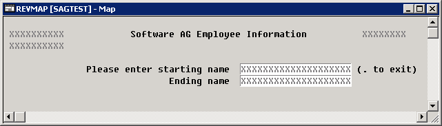
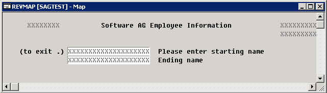
The reversed screen (right-to-left) of this map looks as follows:
With the map profile, you set the profile parameters for the active map. These parameters are saved with the map.
![]() To set profile parameters
To set profile parameters
From the menu, choose .
The SYSPROF - Map Editor Profile dialog box appears.
Set profile parameters. Each parameter is described in the table below.
Choose to save the profile for the active map.
Map editor profile option settings are described in the following table.
Note:
The settings for Zero printing and
Upper case are copied into the field definition when a new
field is created. These settings can be modified for each new field.
| Option | Explanation | |||||||||||||||||||
|---|---|---|---|---|---|---|---|---|---|---|---|---|---|---|---|---|---|---|---|---|
| Format group box: | ||||||||||||||||||||
| Page size | The number of map lines to be edited
(1 - 250). If Standard keys is
selected, the number of lines is restricted to the range 3 -
250. For a map that is output with a WRITE statement,
specify the number of lines of the logical page output, not the map size. The
map can then be output several times on one page.
|
|||||||||||||||||||
| Line size | The number of map columns (5 -
249).
|
|||||||||||||||||||
| Column shift |
Only available in a mapped mainframe environment. Column shift (0 or 1) to be applied to the map. This feature can
be used to address all 80 columns on a 80-column screen (Column
shift = 1, Line size =
80).
|
|||||||||||||||||||
| Layout | The name of the map that serves as standard layout for the current map. You can use this option to simplify the creation of many similar maps by creating one map as the basic layout map with a set of fields to be used by the other fields. In all similar maps, you specify the name of the standard layout map and you only add the fields that are specific to the new map. See also the Dynamic layout option below. | |||||||||||||||||||
| Decimal char. | The character to be used as the decimal notation
character; the default character is a period (.). You can change
the default decimal character with either of the following methods:
|
|||||||||||||||||||
| Print mode |
|
|||||||||||||||||||
| Control var. | The name of an attribute control variable, the
content of which determines the attribute characteristics of fields and texts
that have the attribute definition AD=Y. The attribute
control variable referenced in the map must be defined in the program using
that map.
Removing an attribute control variable from the map editor profile implies that the attribute control variable is removed from the map, too, unless it is associated to any other map field. |
|||||||||||||||||||
| Standard keys | When you select this check box, the last two
lines of the map remain empty so that function key specifications can be
entered at execution time.
When you clear this check box, all lines are used for the map. |
|||||||||||||||||||
| Upper case | When you select this check box, input is
converted to upper case during map execution.
When you clear this check box, input is not converted to upper case during map execution. |
|||||||||||||||||||
| Field sensitive | When you select this check box, the consistency
check for a map field is made as soon as the field is filled by the user.
When you clear this check box, field checking is performed when the map is filled completely. |
|||||||||||||||||||
| Dynamic layout | If you have specified the name of a standard
layout map in the Layout text box, you select this check
box to determine that fields are imported dynamically into the layout at
runtime. This means that you can alter your standard layout and this change
will automatically be reflected in all similar maps using this layout.
When you clear this check box, the standard layout is not used dynamically. |
|||||||||||||||||||
| Zero printing | When you select this check box, numeric fields
that contain all zeroes (print one zero, right-justified) are printed.
When you clear this check box, the printing of numeric fields that contain all zeroes is suppressed. |
|||||||||||||||||||
| Right justified | When you select this check box, numeric and
alphanumeric fields copied from data definitions in other Natural objects are
right-justified.
When you clear this check box, numeric and alphanumeric fields copied from data definitions in other Natural objects are not right justified. |
|||||||||||||||||||
| Manual skip | When you select this check box, the cursor is
not moved automatically to the next field in the map at execution
time, even if the current field is completely filled.
When you clear this check box, the cursor is moved automatically to the next field in the map at execution time. |
|||||||||||||||||||
| Context group box: | ||||||||||||||||||||
| Device check | A device name can be viewed in this field. | |||||||||||||||||||
| WRITE statement | When you select this check box, the result of the
map definition process is a WRITE statement and the resulting
(output) map can be invoked from a program using a WRITE USING
FORM statement. Empty lines at the end of the map are automatically
deleted so that the map can be output several times on one page.
When you clear this check box, the result of the map definition
process is an |
|||||||||||||||||||
| Helproutine | The name of the helproutine or help map that is
called at execution time when the help function is invoked for this map (global
help for the map). The syntax that applies to entering values in the
Helproutine text box corresponds to the syntax of the
HE session parameter described in
HE Parameter
Syntax (Parameter Reference
documentation).
|
|||||||||||||||||||
| Parameters | Parameters can only be defined if a helproutine
or a help map is specified in the Helproutine text box.
Enter the name of the parameter(s) that will be called at execution
time when the help function is invoked. The syntax that applies to entering
values in the Parameters text box corresponds to the
syntax of the Note: |
|||||||||||||||||||
| As field default | Only applies if the
Helproutine text box is filled.
When you select this check box, the helproutine or help map specified for the map applies as the default to each individual field on the map, that is, the name of each field is passed individually to the helproutine or help map. This option can only be chosen if a helproutine or a help map is specified in the Helproutine text box. When you clear this check box, the name of the map is passed to the helproutine or help map specified in the Helproutine text box. |
|||||||||||||||||||
| Position line | The position (line, vertical) where the specified help map is being output. | |||||||||||||||||||
| Column | The position (column, horizontal) where the specified help map is being output. | |||||||||||||||||||
| Help text | When you select this check box, the map is marked
as help text.
When you clear this check box, the map is not marked as help text. |
|||||||||||||||||||
| AutoRuleRank | The rank (priority) assigned to Predict automatic rules when they are linked to the map during field definition. Default is 1. | |||||||||||||||||||
| Filler characters group box: | ||||||||||||||||||||
| Optional, partial | Indicates that a field is optional and can be partially filled. | |||||||||||||||||||
| Optional, complete | Indicates that a field is optional but must be filled completely if it is used. | |||||||||||||||||||
| Required, partial | Indicates that a field is required but can be partially filled. | |||||||||||||||||||
| Required, complete |
Indicates that a field is required and must be filled completely. Note: |
|||||||||||||||||||
You can save a map definition as a source object and/or a cataloged object (generated program) in the current Natural library in the current Natural system file.
For the naming conventions that apply to an object, refer to Object Naming Conventions in the Using Natural Studio documentation.
![]() To save a map as a source object
To save a map as a source object
Proceed as described in Saving Objects in the Using Natural Studio documentation.
![]() To save a map as a source object and/or a cataloged object
To save a map as a source object and/or a cataloged object
Proceed as described in either Stowing Objects or Cataloging Objects in the Using Natural Studio documentation.