
Con-nect SNADS must be configured to function in the SNADS network in which it will participate. This section describes the necessary steps to configure Con-nect SNADS as part of a SNADS network. For details concerning the functions used here, see Maintaining Con-nect SNADS.
This document covers the following topics:
Configuring Con-nect SNADS requires some understanding of SNADS addressing and routing, and knowledge of the SNADS network in which your Con-nect SNADS will participate. This task should, if possible, be performed with assistance from someone in your organization who is responsible for networking and communications planning (in the following sections, this function is referred to as the "network administrator".)
In order to configure Con-nect SNADS to function in the SNADS network in which it will participate, you must complete the following steps:
Initialize multi-node Con-nect .
Initialize the Con-nect SNADS control information.
Create at least one outbound queue for each adjacent node in the SNADS network.
Define routing entries for each SNADS node in your network with which you want to communicate.
Optional - define additional SNADS DUNs and associate these with Con-nect user IDs.
Define the nodes in your SNADS network with which you want to communicate.
Optional - add external addressees (nicknames) for SNADS users at the specified nodes.
These steps are explained in detail on the following pages.
Con-nect SNADS uses the spool file method routines to transfer information from the Con-nect system file to the Con-nect spool file and vice versa.
So that Con-nect SNADS can operate in your environment, you must define your local node for the Con-nect spool file method. For further information, see Define Local Node.
The first step in configuring Con-nect SNADS is the initialization of the Con-nect SNADS control information. Invoke the Initialization function from the "SNADS Administration Menu" to display the following screen:
   9:40 AM             * * *  C O N - N E C T  3  * * *                14.Feb.94
  Cabinet LS                 Control Maintenance                          Friday

         Hop Count:       16              Max Retries:       3
         Status Save:     99 Days         Retry Delay:       2
         Log Level:       0               NPR Node:
         Local Language:  ENGLISH_        Com-plete Receive:
         MRU Orig Seq No: 175             Com-plete Send:

     Local Node Name        CON-NECT System  DB-ID   FNR   Status (A: Active
     --------------------   ---------------  -----   ----  ------  N: Not Acces-
       ________  ________       ________                              sible
                                                                   U: Unknown  )


 Enter-PF1---PF2---PF3---PF4---PF5---PF6---PF7---PF8---PF9---PF10--PF11--PF12---
             Menu  Quit  Add         Modif Erase
 Press a PF-key
|
Specify the following information on the "Control Maintenance" screen:
- Hop Count
The hop count limits the number of connections in which a DIU can travel along the path. The default value is 16. The administrator should verify that this value is correct.
- Status Save
The number of days Con-nect SNADS will wait for status DIUs to be returned in reply to messages sent from Con-nect SNADS. After this period, the relevant messages awaiting confirmation should be deleted by the administrator (see Recipients of a Message Awaiting Confirmation of Delivery). Any status DIUs that are returned after the messages have been deleted are ignored.
- Log Level
The amount of log information to be recorded.
- Local Language
The local language identifier is used to perform a character conversion of text data. The identifier refers to the specifications made in the translation table (CONDTR1) used for the Con-form-to-DCA conversion facility.
- MRU Orig Seq No
Most recently used origin sequence number. This value is generated automatically. It is part of an identifier for distributions sent by Con-nect SNADS.
- Max Retries, Retry Delay
The maximum number of attempts that will be made to establish a connection to an adjacent SNADS node before that connection will be internally marked as out of service, and the interval (in minutes) between attempts. The DIUs that have been queued for transmission across that connection will be held until explicit operator intervention restarts efforts to establish that connection. Timer-driven queues will use the defined interval value.
- NPR Node
The Natural PROCESS ID with which the desired EntireX Broker Services (LU6.2 API) nucleus address can be identified.
- Com-plete Receive
Currently not evaluated.
- Com-plete Send
Only for EntireX Broker Services (LU6.2 API) environments with Com-plete. The name which is assigned to the Com-plete application program CPSEND (used to invoke Con-nect SNADS).
- Local Node Name
The SNADS DSUN by which Con-nect is identified in the SNADS network. Consult your network administrator to ensure that the name satisfies the naming conventions of your SNADS network.
- Con-nect System
This is an identifier for the Con-nect system, previously defined with the Define Local Node function on the "Administration - External Mail Nodes" menu (see Define Local Node).
At least one DSUN must be defined for each Con-nect system that uses Con-nect SNADS (you can specify up to 10 SNADS DSUNs). This allows a single Con-nect system to function as multiple DSUNs in a SNADS network, and allows a single Con-nect SNADS to serve more than one Con-nect system.
Specify all necessary information to adapt the control information to your environment and press PF5 to confirm your entries.
For each adjacent node in the SNADS network, at least one outbound queue must be defined. If your environment uses EntireX Broker Services (LU6.2 API) with Com-plete or in batch mode, you must also define a dummy queue. You can define as many queues as are required for the current environment.
To define an outbound or dummy queue, choose the Queue Maintenance function from the "SNADS Administration Menu". The "SNADS - Queue Maintenance" screen is displayed. Press PF4 to add a queue. As a result the following screen appears:
  10:35                 * * *  C o n - n e c t  3  * * *                8.Mar.04
  Cabinet LS               SNADS - Add/Modify Queue                     X-FMQ-03

     ------------------------------------------------------------------------
     Queue ID:       ________            Description:  ______________________
     Connection ID:  _________________   Mode Name:    ________
     ------------------------------------------------------------------------
     Time Last Active:
     Time Last Deactivated:
     Time Last Scheduled:
     ------------------------------------------------------------------------
     Reset Status (I, T, E, H):  _                  Time Interval:  _____ Min
     Input Status (A, D):        _
     Output Status:
     Mark:          _ Start   _ Stop   _ Reset Queue Server
     ------------------------------------------------------------------------
     Queue Status:
     A : Queue Active                 H : Queue Held          ' ' : Scheduled
     D : Queue being Drained          T : Timer Wait
     I : Queue Inactive               E : Event Wait
     ------------------------------------------------------------------------
 Enter-PF1---PF2---PF3---PF4---PF5---PF6---PF7---PF8---PF9---PF10--PF11--PF12---
             Menu  Quit        Conf
Add queue and press PF5 to confirm |
Specify the following information on the "SNADS - Add/Modify Queue" screen:
- Queue ID
If you are adding a dummy queue, the queue ID must be "***DMY**". Otherwise, this can be any name you want.
- Connection ID
This and the "Mode Name" field, identifies the SNA LU6.2 link used to send SNADS distributions from the queue.
If your system uses Software AG's EntireX Broker Services (LU6.2 API), you must enter the fully qualified LU name which was used to define the adjacent node to the SNA network.
For systems running CICS, this field must match the name this connection used in CICS (TCT entry). You can obtain this information from your network administrator or system programmer.
- Description
Optional - a description of the queue.
- Mode Name
This and the "Connection ID" field, identifies the SNA LU6.2 link used to send SNADS distributions from the queue.
If your system uses EntireX Broker Services (LU6.2 API), you must enter the VTAM log mode name which can be used for the APPC connection with the appropriate adjacent node. You can obtain this information from your VTAM system programmer.
For systems running CICS, you must enter the VTAM log mode name which can be used for an APPC connection with the appropriate adjacent node and which was entered in the CICS TCT for the appropriate connection. In the case of a dummy queue, you must enter the name of an appropriate VTAM log mode which the adjacent SNADS nodes must use to create the connection with the local system. You can obtain this information from your network administrator or system programmer.
- Start/Stop/Reset Queue Server
Mark the corresponding field to start, stop or reset the queue server.
- Queue Status
The status flags are used to control the scheduling of the queue server (see Scheduling the Con-nect SNADS Queue Servers), i.e. the program in Con-nect SNADS which sends items from this queue to the adjacent node via SNADS.
After you have completed your specifications, press PF5 to confirm the addition of the queue.
See SNADS - Display Queue for additional field information.
Note:
You can define more than one outbound queue to a single adjacent
node. This allows you to choose different service levels (see
Service
Levels) or different scheduling policies for distributions
to different addresses sent to or relayed through the same adjacent
node.
For each SNADS node in your network with which you want to communicate, you must define a routing entry which determines how the SNADS DIUs are to be routed to that node. You must know the SNADS nodes within your network with which you want to communicate and their SNADS DSUNs. You can obtain this information from your network administrator.
Select the Routing Entry Maintenance function from the "SNADS Administration Menu". The "Routing Entry Maintenance" screen is displayed. Press PF4 to add a routing entry. As a result, the following screen appears containing default values for priority, protection, capacity and status:
   3:16 PM             * * *  C O N - N E C T  3  * * *                14.Feb.94
  Cabinet LS                    Routing Entry                             Friday

    _________________________________________________________________________

      Recipient Node:     ________ ________

      Priority:           DATA-8_           (FAST,STATUS, DATA-16 .. DATA-1)

      Protection:         YES               (YES, NO)

      Capacity:           INDF              (0K, 4K, INDF: indefinite)

      Status:             A                 (A: active, I: inactive)

      Next Queue:         ________

      Description:        ______________________________
    _________________________________________________________________________


 Enter-PF1---PF2---PF3---PF4---PF5---PF6---PF7---PF8---PF9---PF10--PF11--PF12---
             Menu  Quit        Conf
 Add routing entry
|
Specify the following information on the "Routing Entry" screen:
- Recipient Node
The DSUN of the SNADS node for which routing is to be defined. The DSUN entered here can be generic, i.e. either the REN or both RGN and REN can be specified as an asterisk (*). This allows indirect routing.
You can, for example, choose to route all DIUs via a particular outbound queue to an adjacent SNADS node, perhaps centrally located in your network, and allow all further routing decisions to be handled there.
Or you can route all DIUs for a single Routing Group (RGN) via a single adjacent node, again deferring further routing decisions to administrators at that node.
Decisions such as these are related to network planning and should be made in cooperation with your network administrator.
See Service Levels for an explanation of the values you can enter in the next three fields. Default values for priority, protection and capacity are displayed in the above screen.
- Status
The options are: A (active) and I (inactive). An inactive status allows the SNADS administrator to disable a route temporarily without having to add the routing entry again when it is re-enabled.
- Next Queue
This is an outbound queue which was added in the previous section. It identifies which outbound queue will be used to deliver the SNADS DIUs to the DSU. The destination node for the queue should be the SNADS node which is the next step in the path through the network to the DSU.
There can be more than one path to this DSU, but SNADS DIUs will be sent along the path indicated here.
The queue that should be used depends upon the configuration of the SNADS network; your network administrator should assist you with this decision.
- Description
Optional - a description of the routing entry.
After you have completed your specifications, press PF5 to confirm the addition of the routing entry.
SNADS uses three service level parameters: priority, protection and capacity. These parameters are set for each SNADS DIU and are used to ensure that the DIUs are routed through DSUs providing the requested service. These parameters are displayed on the "Routing Entry" and "DATA Distribution Interchange Unit" screens.
The values of the DIUs sent by Con-nect users are set automatically by Con-nect SNADS.
The values used for routing must be set by the Con-nect SNADS administrator when creating routing table entries.
The parameters are essentially requests for minimum levels of service with no guarantee that they will be fully honored by all SNADS nodes along the distribution path. A SNADS implementation can, for example, handle DIUs with priority values DATA-16 through DATA-1 equally.
Values other than those recommended should only be used when the Con-nect SNADS administrator is aware of the significance of these parameters for SNADS and their possible effects (including their impact on the rest of the SNADS network).
- Priority
This is the transmission priority. Generally, DIUs with higher priority are serviced and delivered before those with lower priority.
Values: FAST (high), STATUS, DATA-16, ... DATA-1 (low)
Values generated for DIUs sent by Con-nect SNADS: DATA-8 or STATUS
- Protection
This is used to request that DIUs be stored on non-volatile storage, i.e. on disk and not in main memory, at relay or destination SNADS nodes. Con-nect SNADS provides protection for all DIUs.
Values: YES, NO
Value generated for DIUs sent by Con-nect SNADS: YES
- Capacity
This requests a maximum size for distribution objects (e.g. messages or documents) sent via SNADS. Con-nect SNADS accommodates distribution objects of virtually unlimited size.
Values:
0K for DIUs without distribution objects.
4K for DIUs with small distribution objects (< 4096 bytes).
INDF for DIUs with large distribution objects (> 4096 bytes).
Values generated for DIUs sent by Con-nect SNADS:
INDF for data DIUs, and
0K for status DIUs.
All Con-nect users automatically have a SNADS DUN consisting of a DGN (Con-nect system ID) and a DEN (Con-nect user ID). Hence no definitions are necessary for Con-nect users to send and receive items via Con-nect SNADS.
However, you can choose to define additional SNADS DUNs and associate these with Con-nect user IDs. To do this, choose the Local User Maintenance function from the "SNADS Administration Menu" to display the "Local User Maintenance" screen and press PF4 to add a local user (see Adding a Local User Entry).
You must define the nodes in your SNADS network with which you want to communicate as external mail nodes. See Add a SNADS Mail Node.
When external mail nodes have been defined for the external SNADS nodes, you can add external addresses for SNADS users at these nodes. You make them publicly available for all Con-nect users by adding them in the Con-nect cabinet SYSCNT with the "ADD Address" command.
A Con-nect user can also add external addresses in his own cabinet with the "ADD Address" command.
The external address is defined as a nickname for one of the external mail node IDs previously created for the SNADS node, and contains a SNADS DUN for a user at that node. Thus, a complete SNADS address (DSUN and DUN) is available to the Con-nect user when sending mail from Con-nect .
SNADS nodes and external addresses (defined as nicknames for these nodes and specifying SNADS DUNs for users at these nodes) are available to Con-nect users as addressees with the Con-nect Send function. When a partially defined SNADS external address (e.g. an external mail node specifying only a SNADS DSUN, or an external address with an unspecified DEN) is used as an addressee when sending mail from Con-nect , the user is prompted to enter the missing information.
The nodes in your SNADS network with which you want to communicate must be defined as external mail nodes. To add a SNADS mail node, display the "Administration - Add Mail Node" screen:
enter the name of the new node in the "Mail Node/Type" field at the bottom of the "Administration - External Mail Node" screen,
mark the "Add Mail Node" field and press ENTER.
The name that you specified for the external node is the name by which the node will be known to Con-nect .
Enter the necessary information on the "Administration - Add Mail Node" screen. See Add a Mail Node. Once you have specified the address level and node type (F - SNADS), press ENTER to display the following window:
   1:58 PM             * * *  C O N - N E C T  3  * * *                14.Feb.94
  Cabinet LS             Administration - Add Mail Node                   Friday


          Node Name  NEWYORK_
               --------------------------------------------------
        Descri I                                                I
               I               SNADS Node NEWYORK               I
      Address  I                                                I
               I                                                I
          Node I   Recipient Node ID:  ________    ________     I
               I                       (Group)    (Element)     I
  A Con-nect   I                                                I G Printer
  H Telefax    I                                                I
               --------------------------------------------------


          Program name will be built from 'X-' Node type and 'S'

 Enter-PF1---PF2---PF3---PF4---PF5---PF6---PF7---PF8---PF9---PF10--PF11--PF12---
       Help  Menu  Quit        Disp
|
Enter the SNADS DSUN for the external node. You can obtain this from your network administrator:
- Recipient Node ID (Group)
Optional - RGN (Routing Group Name).
- Recipient Node ID (Element)
Mandatory - REN (Routing Element Name).
The DSUN can be specified in a fully or partially qualified form.
To specify the DSUN in a partially qualified form, you must enter an asterisk (*) in the appropriate field. When a user specifies this node (either while sending mail to this node or while creating a nickname for the node), the user must supply either the REN or both the RGN and REN.
To specify a DSUN which only contains the REN component, you must enter only the REN (element) and leave the RGN field (group) blank. Since the RGN field has been left blank, the user cannot enter any information in this field.
After you have completed your specifications, press ENTER to add the mail node.
For details on how to modify, display and delete mail nodes, see External Mail Nodes.
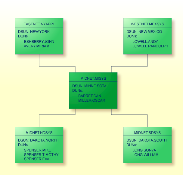
This section describes a sample SNADS network and provides three examples of SNADS nodes to clarify SNADS addressing and routing. The configurations for the outbound queue and routing entries are given for each node as they would appear in Con-nect SNADS for that node. If other systems interface with SNADS (e.g. DISOSS), similar addressing and routing information must be defined, in a different form.
Notes:
A generic entry (DAKOTA.*) is used to route all DIUs which originate from users at NEW.YORK for recipients in routing group DAKOTA through the intermediate node MINNE.SOTA. Further routing to DAKOTA.NORTH or DAKOTA.SOUTH is handled by the routing entries at MINNE.SOTA.
The following routing entries are defined at NEW.YORK:
| Destination Node | Queue |
|---|---|
| MINNE.SOTA | MINNE-Q |
| NEW.MEXICO | MINNE-Q |
| DAKOTA.* | MINNE-Q |
In this sample network, a Con-nect administrator at NEW.YORK might create an external node NDAKOTA, as type F for SNADS and defined as (DSUN):
Recipient Node ID (Group): DAKOTA (RGN)
Recipient Node ID (Element): NORTH (REN)
A Con-nect user can then create an external addressee SPENSER as a nickname for this node. The node is now defined as (DUN):
Recipient User ID (Group): SPENSER (DGN)
Recipient User ID (Element): (unspecified DEN)
The unspecified DEN of the SNADS address is provided by the Con-nect user, such as EVA when using this address in the Send function.
Alternatively, an external address, EVA, can be created as a nickname for NDAKOTA, with the SNADS DUN fully specified as SPENSER.EVA.
Two destination nodes are fully defined (MINNE.SOTA and NEW.MEXICO). A generic entry (DAKOTA.*) is used for all DIUs to either DAKOTA.NORTH or DAKOTA.SOUTH.
Most of the routing errors can be detected in NEW.YORK. However, if a DIU is addressed to the non-existing node DAKOTA.MIDDLE, the routing error is not detected until the next node in this network (MINNE.SOTA).
This is another example that uses external addressees in Con-nect to communicate with users in a SNADS network.
The following queues are defined at MINNE.SOTA:
| Queue ID | CICS TCT Name | LU Name |
|---|---|---|
| YORK-Q | NYRK | EASTNET.NYAPPL |
| MEXICO-Q | NMEX | WESTNET.MEXSYS |
| DAKOTA-N | NDAK | MIDNET.NDSYS |
| DAKOTA-S | SDAK | MIDNET.SDSYS |
The following routing entries are defined at MINNE.SOTA:
| Destination Node | Queue |
|---|---|
| NEW.YORK | YORK-Q |
| NEW.MEXICO | MEXICO-Q |
| DAKOTA.NORTH | DAKOTA-N |
| DAKOTA.SOUTH | DAKOTA-S |
When NEW.YORK, DAKOTA.NORTH and DAKOTA.SOUTH are defined at MINNE.SOTA as external nodes, user MILLER.OSCAR at MINNE.SOTA can define the following external addressees as nicknames for these external nodes:
| Nickname | External Node | External Addressee |
|---|---|---|
| John | NEW.YORK | ESHBERRY.JOHN |
| Miriam | NEW.YORK | AVERY.MIRIAM |
| Eva | DAKOTA.NORTH | SPENSER.EVA |
| Sonya | DAKOTA.SOUTH | LONG.SONYA |
At DAKOTA.NORTH, generic routing is used to route all DIUs via MINNE.SOTA.
For example, a DIU sent from DAKOTA.NORTH to ESHBERRY.JOHN (DUN) at NEW.YORK (DSUN) can be routed via the generic routing entry *.* to MINNE.SOTA, where its routing table contains an entry which routes the DIU to its destination at NEW.YORK.
Thus, DAKOTA.NORTH can offload the task of maintaining extensive routing entries for other nodes in the network to MINNE.SOTA, thus minimizing the network management at that node.
In this configuration MINNE.SOTA functions as a "gateway node", via which the nodes in routing group DAKOTA connect with the nodes in the rest of the network.
| Destination Node | Queue |
|---|---|
| *.* | MINNE-Q |
All DIUs at DAKOTA.NORTH are sent via the generic routing entry *.* to MINNE.SOTA. Therefore, routing errors (i.e. DSUNs which are not known within the network) cannot be detected at DAKOTA.NORTH.