Select Start, point to Programs, and select the IBM Communications Server SNA Node Configuration application. Select Scenarios on the main menu. The Choose a Configuration dialog box displays. Select APPN Network Node, and then click the Finish button to return to the Communications Server SNA Node Configuration window.
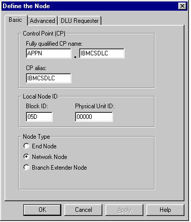
Double-click Network Node Setup in the left pane. The Define The Node dialog box appears. For this example, the netid is defined as APPN and the server node is defined as IBMCSDLC under CP Name and CP Alias. Note that the Network Node option is selected under Node Type. Accept the defaults for Block ID and Physical Unit ID, and for the Advanced and DLU Requester tabs. Click the OK button to return to the Communications Server SNA Node Configuration window.
Double-click Device Configuration in the left pane. Select Devices in the Definition Hierarchy by Function pane, and then click the Create button. The Device Type dialog box appears. Choose LAN in the list box; and then click the OK button to return to the Communications Server SNA Node Configuration window.
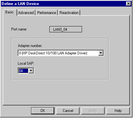
Expand the LAN folder in the right pane. The Define a LAN Device dialog box appears. Select or accept the current LAN Adapter described on the Basic tab. Accept the defaults displayed on the Advanced, Performance, and Reactivation tabs, and then click the OK button to return to the Communications Server SNA Node Configuration window.
Double-click Peer Connection Configuration in the left pane. Expand the CPI_C and APPC and Peer Connections nodes in the right pane. Select Peer Connections, and then click the Create button.
The Define a LAN Connection dialog box appears. Accept the defaults, and type the LAN adapter (MAC) address of the target OS/400 in the Destination Address text box. The LAN adapter address can be displayed via the OS/400 WRKLIND command. If you are not authorized to use this
command, ask your OS/400 systems administrator for the target machine LAN adapter (MAC) address.
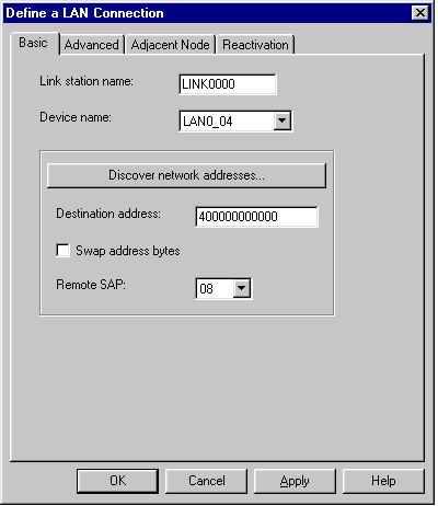
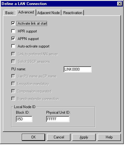
Select the Advanced tab; check the APPN Support check box, and then type a Block ID = 05D and a node ID in the range of 00000 to FFFFF under Local Node ID. Verify that the Activate Link at Start and APPN Support check boxes are selected.
Select the Adjacent Node tab; enter the Adjacent CP Name = APPN.CONNX400 in this example. This value must match the output of the DSPNETA command.
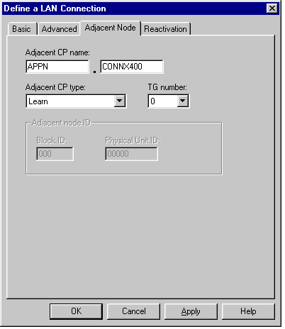
Accept the defaults for the Reactivation tab (not shown). Click the OK button to return to the Communications Server SNA Node Configuration window.
Double-click the Partner LU 6.2 Configuration in the right pane, and then click the Create button. The Define a Partner LU 6.2 dialog box appears. Type the Net ID and the System name of the target OS/400, which should match the Local Network ID and Local Control Field Name fields as displayed by the OS/400
DSPNETA command. Also define a partner LU alias and a fully qualified control point (CP) name = netid.system, or in this example, APPN.CONNX400.
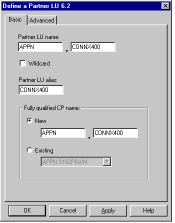
View and accept the defaults for the Advanced tab (not shown), and then click the OK button to return to the Communications Server SNA Node Configuration window.
Click the Local LU 6.2 LUs check box in the right pane, and then click the Create button. The Define a Local LU 6.2 dialog box appears. Define a local LU and a local LU alias. For simplicity, these are both = IBMDLC01.
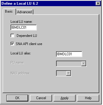
Accept the defaults for the Advanced tab (not shown), and then click the OK button to return to the Communications Server SNA Node.
Click within the Modes pane and then click the Create button. Define mode name IBMRDB as shown, and then accept the default values shown on the Advanced tab. Click the OK button to return to the Communications Server SNA Node Configuration window.
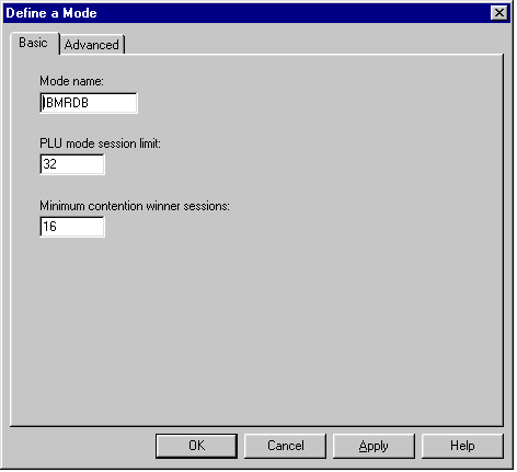
Select Transaction Program in the CPI-C and APPC node in the Communications Server SNA Node Configuration dialog box, and then click the Create button.
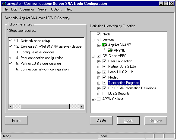
The Define a Transaction Program dialog box appears.
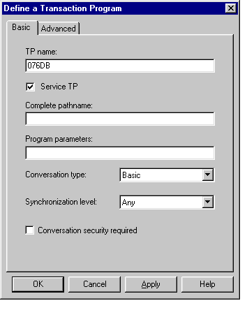
Enter the name of the transaction program in the TP name text box, and then check the Service TP check box. This is the name of the DRDA APPC transaction program, which is predefined at the target AS/400 system. Select the Advanced tab.
Verify that the For SNA API Client Use check box is checked.
Expand APPN Options and APPN Connection Networks. In the right pane, click the Create button.
The Define a Connection Network dialog box appears. Define the network name = netid.luname of the target OS/400. Click the OK button to return to the Communications Server SNA Node Configuration window.
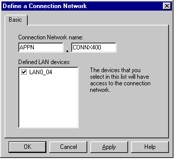
Select Save on the File menu and start the connection.