
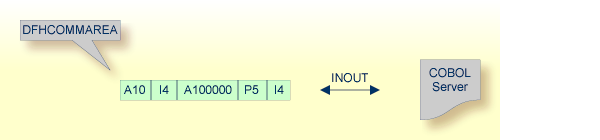
This document describes using the COBOL Mapping Editor to extract from a CICS DFHCOMMAREA program where COBOL output parameters are the same as COBOL input parameters, that is, the DFHCOMMAREA on output is not overlaid with a data structure different to the data structure on input.
Depending on the programming style used in the CICS program and the
various different techniques for accessing the CICS DFHCOMMAREA interface,
finding the relevant COBOL data structures can be a complex and time-consuming
task that may require CICS COBOL programming knowledge. Please note also the
following:
A CICS program does not require a PROCEDURE DIVISION
header, where parameters are normally defined. See PROCEDURE DIVISION Mapping.
The DFHCOMMAEA can be omitted in the linkage
section.
If there is no DFHCOMMAREA in the linkage section or no
PROCEDURE DIVISION header present in the PROCEDURE
DIVISION, the CICS preprocessor completes the interface of the COBOL
server and adds a DFHCOMMAREA and a PROCEDURE DIVISON
header to the CICS program before compilation.
If you have selected an IDL file and opened the COBOL Mapping Editor with an existing COBOL to IDL mapping, continue with Mapping Editor User Interface.
This section assumes Input Message same as Output Message is checked. COBOL output and COBOL input parameters are the same, that is, the DFHCOMMAREA on output is not overlaid with a data structure different to the data structure on input.
If you are extracting IDL from a COBOL source or extending the IDL file by extracting an additional COBOL source with interface type CICS with DFHCOMMAREA calling convention, the Extractor Settings dialog appears (see also Step 4: Define the Extraction Settings and Start Extraction).
Make sure the interface type is correct and checkbox Input Message same as Output Message is not cleared.
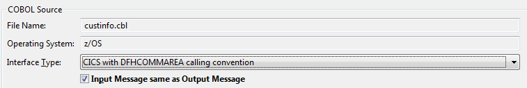
Press to open the COBOL Mapping Editor.
![]() To select the COBOL interface data items of your COBOL server
To select the COBOL interface data items of your COBOL server
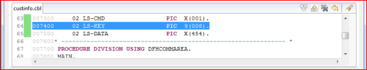
Add the COBOL data items of the CICS message to COBOL Interface by using the context menu or toolbar available in the COBOL Source View and COBOL Interface. See Notes.
Continue with COBOL to IDL Mapping.
Notes:
DFHCOMMAREA is present,
the DFHCOMMAREA COBOL data item itself cannot be selected.
In this case, select the COBOL data items directly subordinated to DFHCOMMAREA
and map to IDL.
See Map to In, Out, InOut.
REDEFINEs, the first REDEFINE path is
offered by default. Check manually whether this is the one you want. If not,
correct it. You can select any other REDEFINE path.
The user interface of the COBOL Mapping Editor is described below.
This section assumes you have set the extraction settings as described above. The following areas of the COBOL Mapping Editor user interface are described here:
For COBOL interface type CICS with DFHCOMMAREA interface, the user interface of the COBOL Mapping Editor looks like this:
 |
COBOL Program Selection. Currently selected program with interface type
 More info More info |
 |
COBOL Source View. Contains all related sources for the currently selected COBOL program
More info |
 |
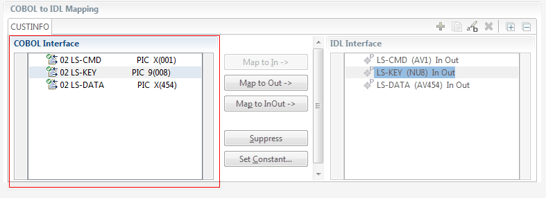
COBOL to IDL Mapping. Tree view of your selected COBOL data items and mapping buttons with which you can map these items to your IDL interface
More info |

The COBOL Program Selection displays the current selected COBOL program with its interface type. If you have extracted more than one COBOL program within the associated IDL file, you can switch to another COBOL program with its mapping by selecting the name in the combo box.
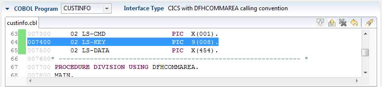
All COBOL data items contained in the LINKAGE and WORKING-STORAGE SECTION
are offered in a text view. The text view contains all related sources (including copybooks) for the currently
selected COBOL program. It is used for selecting data items and retrieving information from
the original COBOL sources. The light green bar indicates that the data item is already contained in the COBOL Interface;
a dark green bar indicates the data item is selectable and can be added to the COBOL Interface.
This section can be collapsed. If you open the Editor with Modify Interface
it is collapsed by default. The toolbar provides the following actions:
| Add selected COBOL data item to COBOL Interface. | |
| Remove selected COBOL data item from COBOL Interface. | |
| Remove all COBOL data items from COBOL Interface. | |
| Reset COBOL Interface to initial state. | |
| Show dialog to find text in Source. |
The same functionality is also available from the context menu.
This section covers the following topics:
The COBOL Interface shows a tree view of your selected COBOL data items describing the interface of the COBOL server. A context menu is available for the COBOL data items, which provides mapping and other functions. On some COBOL data items, decision icons indicate where particular attention is needed, including mapping icons to visualize the COBOL data type and your current mapping.
The COBOL data item names are derived from the COBOL source from which they were extracted.
If your COBOL interface contains parameters without a name, that
is, the keyword FILLER is used, those COBOL data items are shown as
[FILLER]. See FILLER Pseudo-Parameter.
You can modify the COBOL interface using context menu or toolbar; decision and mapping icons provide additional information.
- Context Menu
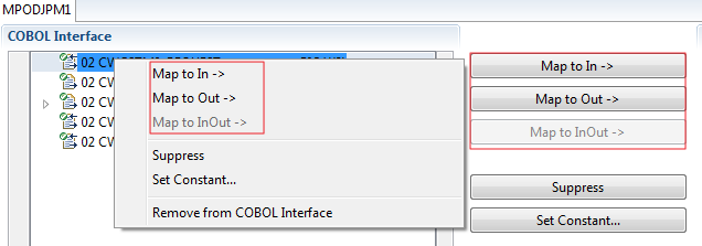
The context menu on COBOL data items provides the following mapping and other functions, depending on the data item type, the COBOL level and the current mapping.
A suppressed COBOL data item becomes visible in the IDL interface. Used also to select another REDEFINEpath.Suppress unneeded COBOL data items. Set COBOL data items to constant. Set COBOL data items where the server program decides the output structure used on return. Specify the set of multiple possible output (MPO) structures and the criteria when a structure is used. Remove the data item from the COBOL interface. This also removes the mapped IDL parameter from all IDL interfaces for the current COBOL program. See COBOL Program Selection. - Toolbar
The toolbar offers the following actions:
Create IDL Interface. Creates a new IDL interface based on the current COBOL interface: all IDL parameters are of IDL direction InOut; no IDL parameters are set to constant; for COBOL REDEFINE, the firstREDEFINEpath is mapped to IDL;FILLERs are suppressed according to your selection, see Step 4: Define the Extraction Settings and Start Extraction.Copy current IDL Interface. Creates a duplicate of the current IDL interface: all modifications such as IDL directions, suppress, selection of REDEFINEpaths etc. are kept.Remove current IDL Interface. Rename current IDL Interface. Expand the full tree. Collapse the full tree. See also Map to Multiple IDL Interfaces.
- Decision Icons
The decision icons in the first column are set on COBOL data items where particular attention is needed:
This icon visualizes a COBOL REDEFINE. It is essential that you map the correct redefine path for your mapping to In, Out or InOut using the context menu. If you map aREDEFINEpath, all other siblingREDEFINEpaths are automatically set to "Suppress".- Mapping Icons
The following mapping icons on the COBOL data items indicate your current IDL mapping:
Scalar parameter, mapped to In. Scalar parameter, mapped to InOut. Scalar parameter, mapped to Out. Group parameter, here mapped to InOut. REDEFINEparameter, here mapped to InOut.Parameter set to Constant.
The following buttons are available:
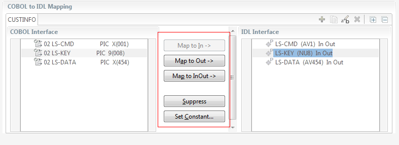
- Map to In | Out | InOut ->
See Map to In, Out, InOut. A suppressed COBOL data item becomes visible in the IDL interface. Used also to select another
REDEFINEpath.- Suppress
See Suppress Unneeded COBOL Data Items.
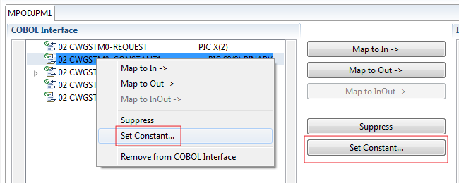
- Set Constant...
See Set COBOL Data Items to Constants.
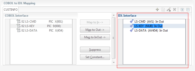
If you have mapped the COBOL interface to multiple IDL interfaces, select the IDL interface by choosing the tabs. In the IDL Interface tree view, a context menu is also available with the following possibilities:
Rename
Remove from COBOL Interface. This also removes the mapped IDL parameter from all IDL interfaces for the current COBOL program. See COBOL Program Selection above.
This section covers the following topics:
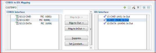
With the Map to In, Out, InOut functions you make a COBOL data item visible as an IDL parameter in the IDL interface. With correct IDL directions you design the IDL interface by defining input and output parameters. COBOL programs have no parameter directions, so you need to set IDL directions manually.
![]() To provide IDL directions
To provide IDL directions
Go step-by-step through all top-level COBOL data items in the COBOL interface and use the , and functions available in the context menu of the COBOL interface and as mapping buttons to make the COBOL data items visible and provide IDL directions in the IDL interface:
Notes:
attribute-list under Software AG IDL Grammar.
If you are using an RPC server such as the z/OS (CICS | Batch), z/VSE (CICS | Batch), Micro Focus or BS2000/OSD RPC server, the amount of data to be transferred to/from the RPC client is reduced with correct IDL directions.
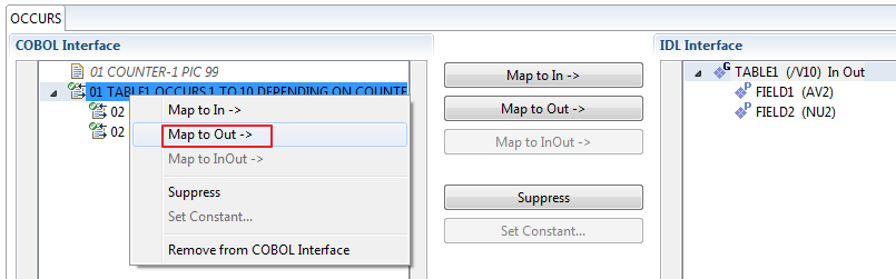
With the , , functions you can make the COBOL ODO subject (here COBOL data item TABLE)
of a variable-sized COBOL table (see COBOL Tables with Variable Size - DEPENDING ON Clause) visible as an IDL unbounded group (with maximum).
The ODO object (here COBOL data item COUNTER-1) is suppressed and therefore not part of the IDL interface.
This is because the number of elements of the IDL unbounded group is already implicitly available. See the following example:
01 COUNTER-1 PIC 99.
01 TABLE OCCURS 1 TO 10 DEPENDING ON COUNTER-1
 02 FIELD1 PIC XX.
 02 FIELD2 PIC 99.
![]() To map
To map OCCURS DEPENDING ON
Add the COBOL ODO subject (here data item TABLE) and ODO object (here data item COUNTER-1)
to the COBOL interface. It is important both data items are in the COBOL interface.
Use the , and functions available in the context menu of the COBOL interface and as mapping buttons and apply IDL directions for the ODO
subject (data item TABLE):
Notes:
attribute-list under Software AG IDL Grammar.
Assume the COBOL server program provides multiple functions or operations, in the following example ADD, SUBRACT, MULTIPLY.
Some dispatcher front-end code executes the correct function, for example, depending on a function-code or operation-code parameter:
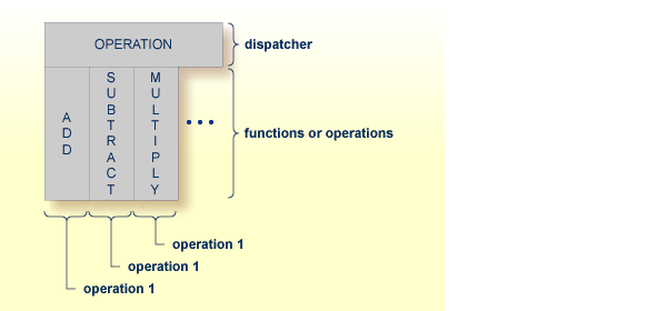
This example is described in more detail under Example 1: COBOL Server with Multiple Functions.
If you have such a situation, a good approach is to expose each COBOL server program function separately as an IDL program. This gives advantages in further processing of the IDL and COBOL mapping files (SVM and CVM). For example:
If your target endpoint is a web service: instead having a Web service with a single operation, you get a web service with multiple operation, one operation for each COBOL function.
If your target endpoint is Java or .NET: instead having a class with a single method, you get a class with multiple methods, one method for each COBOL function.
![]() To map a COBOL interface to multiple IDL interfaces
To map a COBOL interface to multiple IDL interfaces
Select the tab with COBOL to IDL Mapping. For each function, define a separate IDL interface with the toolbar functions ![]() or
or ![]() :
:
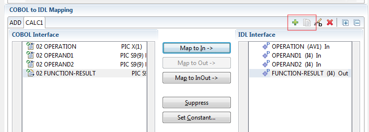
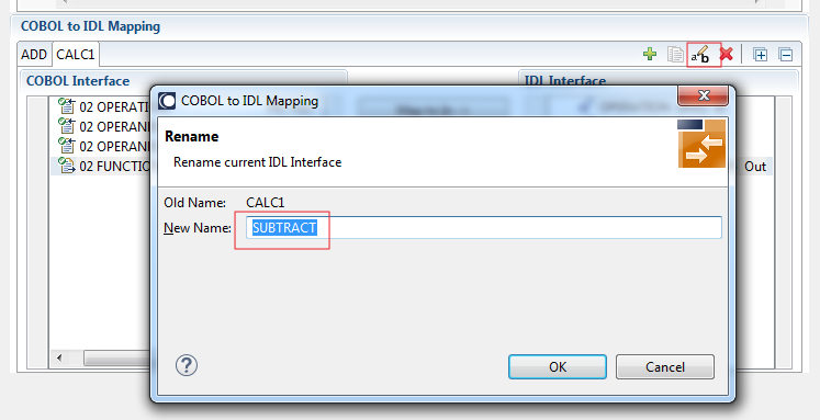
Give the IDL interfaces meaningful names with the toolbar function ![]() :
:
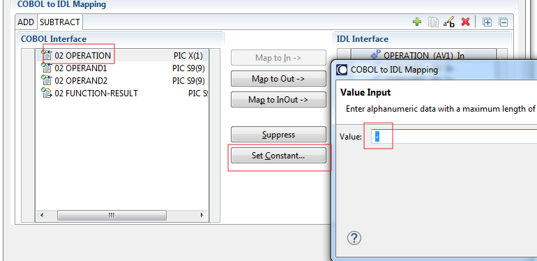
Define the required constant values to the function-code or operation-code parameter, see Set COBOL Data Items to Constants above:
For the delivered Example 1: COBOL Server with Multiple Functions:
First, for step 1 above: Extract and define 3 separate IDL programs ADD, SUBTRACT, MULTIPLY.
Second, for step 2 above: Rename them to suitabable names, e.g. 'ADD', 'SUBTRACT', MULTIPLY'
Third, for step 3 above: Define the constants '+', '-' and '*' to the parameter OPERATION respectively.
After pressing , the following IDL together with a server mapping file is created. See Server Mapping Files for COBOL.
library 'EXAMPLE' is

 program 'ADD' is
  define data parameter
   1 OPERAND1 (I4) In
   1 OPERAND2 (I4) In
   1 FUNCTION-RESULT (I4) Out
  end-define

 program 'SUBTRACT' is
  define data parameter
   1 OPERAND1 (I4) In
   1 OPERAND2 (I4) In
   1 FUNCTION-RESULT (I4) Out
  end-define

 program 'MULTIPLY' is
  define data parameter
   1 OPERAND1 (I4) In
   1 OPERAND2 (I4) In
   1 FUNCTION-RESULT (I4) Out
  end-define
Notes:
| Icon | Function | Description |
|---|---|---|
| Create IDL Interface | Creates a new IDL interface based on the current COBOL interface. All IDL parameters are of IDL direction InOut; no IDL parameters
are set to constant; for COBOL REDEFINE, the first REDEFINE path is mapped to IDL; FILLERs are suppressed according to your selection, see Step 4: Define the Extraction Settings and Start Extraction.
|
|
| Copy current IDL Interface | Creates a duplicate of current IDL interface. All modifications such as IDL directions, suppress, selection of REDEFINE paths etc. are kept.
|
|
| Rename current IDL Interface | The default name for the IDL interface is based on the COBOL program name plus appended number. With this function you can give the IDL interface a suitable name. | |
| Remove current IDL Interface | Deletes the current IDL interface. |
For COBOL server programs containing COBOL REDEFINEs, the correct REDEFINE path needs to be chosen for the IDL interface.
![]() To select redefine paths
To select redefine paths
Use the , or functions available in the context menu of the COBOL interface and as mapping buttons to make the COBOL REDEFINE path available in the IDL interface.
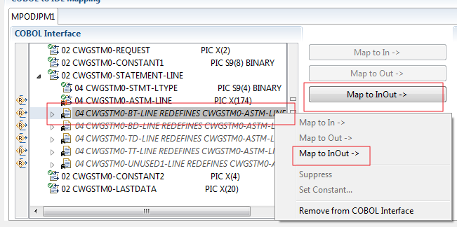
Begin with the COBOL REDEFINE defined at the highest level first. Work through all inner COBOL REDEFINE data items, going from higher levels to lower levels.
Notes:
REDEFINE path of a COBOL REDEFINE can be mapped to the IDL interface. All COBOL REDEFINE siblings are suppressed.
REDEFINE path is actively mapped to the IDL interface, all COBOL REDEFINE siblings are suppressed.
REDEFINE paths of a COBOL REDEFINE. Simply suppress the active REDEFINE path, see Suppress Unneeded COBOL Data Items above.
COBOL data items without any relevant information can be made invisible in the IDL interface. The IDL interface is simplified - it becomes shorter and tidier. This is useful, for example
for FILLER data items
if the RPC client or Adapter Service does not need an Out parameter
if the RPC server or Adapter Service does not need an In parameter and a low value can be provided
If you are using an RPC server such as the z/OS (CICS | Batch), z/VSE (CICS | Batch), Micro Focus or BS2000/OSD RPC server, the amount of data to be transferred to/from the RPC client is also reduced.
![]() To suppress unneeded COBOL data items
To suppress unneeded COBOL data items
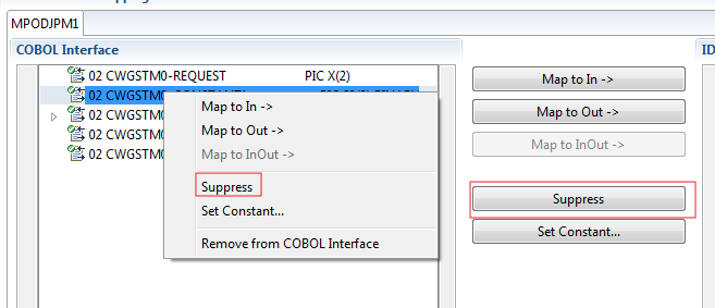
Use the function available in the context menu of the COBOL interface and as mapping button to make the COBOL data item invisible in the IDL interface:
Notes:
COBOL data items that always require fixed constant values on input to the COBOL server program can be made invisible in the
IDL interface and initialized with the required constant values.
This is useful for keeping the IDL interface short and tidy. RPC clients or Adapter Services are not bothered with IDL
parameters that always contain constants, such as RECORD-TYPES.
This function is often used in conjunction with (see above).
![]() To COBOL data items to constants
To COBOL data items to constants
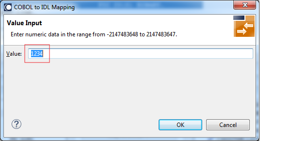
Use the function available in the context menu of the COBOL interface and as mapping button to define a constant value for a COBOL data item:
You are prompted with a window to enter the constant value:
Notes:
A COBOL server program produces more than one type of output. The layout of the output can therefore take two or more dissimilar shapes. The COBOL server program decides at runtime the output structure returned, that is, the COBOL layout on output varies.
As illustrated in Example 5: COBOL Server Using Multiple Possible Output (MPO), a COBOL REDEFINES Clause is often used to describe the possible output structures. In COBOL this is the standard way to describe multiple possible
output.
In addition, the COBOL interface
limits the number of possible output structures returned
defines all possible output structures, that is, they are known during extraction. In the example these are the structures
PAYMENT-DATA-VOUCHER, PAYMENT-DATA-CREDITCARD and PAYMENT-DATA-TRANSFER. These are the MPO structures.
contains an additional COBOL data item carrying a value related to the returned output structure. By inspecting this data
item first, the appropriate output structure can be selected to address the data correctly. In the example it is PAYMENT-TYPE. This item is the MPO selector.
always occupies memory to be able to transfer the longest output structure. If the actual returned output structure is shorter than the longest possible output structure, there is a gap (space) between the multiple possible output and the subsequent data item.
This abstract concept is known as multiple possible output (MPO) EntireX bundles all MPO structures into an MPO group. See MPO Terminology below.
As illustrated in Example 6: COBOL Server Using Optional Output, COBOL group data items can be used to describe optional output structures. See Optional COBOL Group Data Items. Optional output with group data items are a variant of multiple possible output (MPO).
In addition, the COBOL interface
limits the number of possible output structures returned
defines all optional output structures, that is, they are known during extraction. In the example these are the structures
OPTIONAL-OUTPUT-STRUCTURE1 and OPTIONAL-OUTPUT-STRUCTURE2. These are the MPO structures.
contains an additional COBOL data item carrying an indication if the optional output is present. By inspecting this data item
first, the appropriate optional output structure can be selected to address the data correctly. If its value does not match,
the optional output is not present. In the example it is OPTIONAL-OUTPUT. This item is the MPO selector.
If the optional output is not present no memory is occupied. There is no gap between the optional output and the subsequent
data item, as opposed to Multiple Possible Output with REDEFINES above.
In the example there are three different shapes of output:
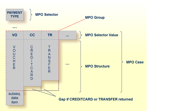
The following terminology is used with MPOs:
- MPO structure
A COBOL group describing the output layout used in an MPO case. All alternative layouts in an MPO group are often described with COBOL
REDEFINEs. An MPO structure can also contain other MPO groups.- MPO group
Bundles together all MPO structures that can be used alternatively. A COBOL interface can contain more than one MPO group.
- MPO case
An MPO structure together with its MPO selector values (one or more).
- MPO selector
A COBOL data item containing a specific value (MPO selector value) where the actual MPO case can be determined. The MPO selector precedes the MPO group and is located outside the MPO group.
- MPO selector value
Each value indicates exactly one output structure. An output structure can be indicated by further values.
![]() To set multiple possible output (MPO) structures
To set multiple possible output (MPO) structures
Use the function available in the context menu of the COBOL interface to create new or modify existing MPO groups.
Set the top-level COBOL data item where the MPO structures are contained to IDL direction Out. Use the function for this purpose:
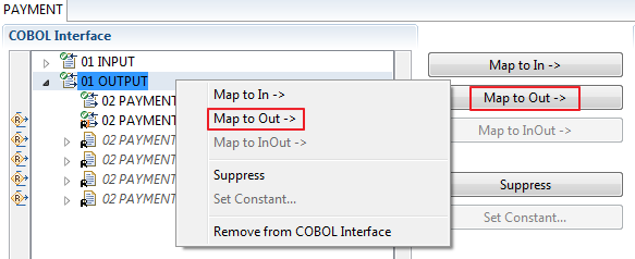
From the context menu of the COBOL interface of the COBOL REDEFINE, choose .
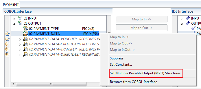
Set Multiple Possible Output (MPO) Structures into MPO Group.
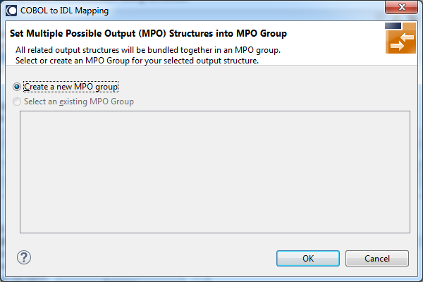
Create a new MPO group.
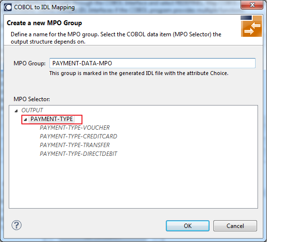
Set MPO selector values for MPO Structures.
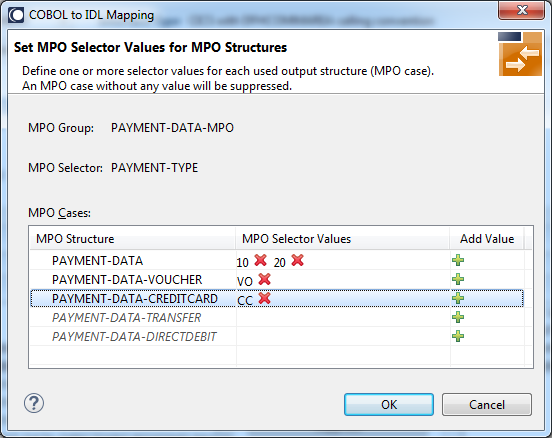
Use the functions ![]() to delete and
to delete and ![]() to add MPO selector values:
to add MPO selector values:
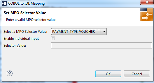
Notes:
PAYMENT-DATA).
PAYMENT-DATA-TRANSFER).
For the delivered example COBOL Server Using Multiple Possible Output (MPO) (see below): After pressing , the following IDL together with a server mapping file is created. See Server Mapping Files for COBOL.
library 'PAYMENT' is

 program 'PAYMENT' is
  define data parameter
   1 INPUT              In
    2 ORDER-NUMBER             (NU10)
   1 OUTPUT             Out
    2 PAYMENT-TYPE             (A2)
    2 PAYMENT-DATA-MPO  Choice
     3 PAYMENT-DATA            (/V1)
      4 PAYMENT-DATA           (AV256)
     3 PAYMENT-DATA-VOUCHER    (/V1)
      4 VOUCHER-ORIGIN         (AV128)
      4 VOUCHER-SERIES         (AV128)
     3 PAYMENT-DATA-CREDITCARD (/V1)
      4 CREDITCARD-NUMBER      (NU18)
      4 CREDITCARD-CODE        (NU12)
      4 CREDITCARD-VALIDITY    (AV8)
  end-define
Assume a COBOL server program has a FUNCTION or OPERATION code COBOL data item in its COBOL interface.
The COBOL server program behaves differently depending on field values of this data item.
See the following example where a COBOL programs implements a calculator with the functions ADD, SUBTRACT, MULTIPLY, etc.
The execution of the different functions is controlled by the COBOL data item OPERATION:
. . .

     01 OPERATION                      PIC X(1).
     01 OPERAND1                       PIC S9(9) BINARY.
     01 OPERAND2                       PIC S9(9) BINARY.
     01 FUNCTION-RESULT                PIC S9(9) BINARY.
     . . .
     MOVE 0 TO FUNCTION-RESULT.
     EVALUATE OPERATION
         WHEN "+"
            ADD OPERAND1 OPERAND2
            GIVING FUNCTION-RESULT
         WHEN "-"
            SUBTRACT OPERAND2 FROM OPERAND1
            GIVING FUNCTION-RESULT
         WHEN "*"
            MULTIPLY OPERAND1 BY OPERAND2
            GIVING FUNCTION-RESULT
         WHEN . . .

     END-EVALUATE.
. . .
You can expose each COBOL server program function separately. The advantages or reasons for wanting this depend on the target endpoint. For example:
Web Service
Instead having a Web service with a single operation, you want a web service with multiple operations, one operation for each
COBOL function.
Java or .NET
Instead having a class with a single method, you want a class with multiple methods, one method for each COBOL function.
etc.
To do this you need to extract the COBOL server program as described under Map to Multiple IDL Interfaces.
The input and output data is described with a REDEFINE as in the following example.
In this case you need to select REDEFINE path BUFFER2 for the COBOL interface.
 LINKAGE SECTION.
 01 DFHCOMMAREA.

 02 BUFFER1.
    03 FIELD-1                        PIC X(4).
    03 FIELD-2                        PIC X(2).
 . . .
 02 BUFFER2 REDEFINES BUFFER1.
    03 OPERATION                      PIC X(1).
    03 OPERAND-1                      PIC S9(9) BINARY.
    03 OPERAND-2                      PIC S9(9) BINARY.
    03 FUNCTION-RESULT                PIC S9(9) BINARY.
  . . .
 PROCEDURE DIVISION USING DFHCOMMAREA.
* process BUFFER2
    EXEC CICS RETURN.
Often a similar looking technique is used to allow full 32K input and full 32K completely different output, thus circumventing
CICS 32K restrictions somewhat:
A REDEFINE is used to describe output data that overlays the input data, that is,
the CICS input message is different to CICS output message.
For more information see Example 2: Redefines in section CICS with DFHCOMMAREA Calling Convention - In different to Out.
On entry, the server moves linkage section field(s) - often an
entire buffer - into the working storage and processes the input data inside
the working storage field(s). Before return, it moves the working storage
field(s) - often an entire buffer - back to the linkage section. In this case,
the relevant COBOL data items are described within the working storage
section. You need to select WS-BUFFER for the COBOL interface.
 WORKING STORAGE SECTION.
 01 WS-BUFFER.
    02 OPERATION                      PIC X(1).
    02 OPERAND-1                      PIC S9(9) BINARY.
    02 OPERAND-2                      PIC S9(9) BINARY.
    02 FUNCTION-RESULT                PIC S9(9) BINARY.
 LINKAGE SECTION.
 01 DFHCOMMAREA.
    02 IO-BUFFER                      PIC X(9).
 . . .
 PROCEDURE DIVISION USING DFHCOMMAREA.
    MOVE IO-BUFFER TO WS-BUFFER.
* process the WS-BUFFER and provide result in WS-BUFFER
    MOVE WS-BUFFER TO IO-BUFFER.
    EXEC CICS RETURN.
A similar looking technique is used to allow full 32K input and full 32K completely different output, thus circumventing CICS
32K restrictions somewhat:
The buffer technique may be used to describe output data that overlays the input data, that is,
the CICS input message is different to CICS output message. For more information see Example 3: Buffer Technique in section CICS with DFHCOMMAREA Calling Convention - In different to Out.
COBOL SET ADDRESS statements are used to manipulate the
interface of the CICS server. On entry, the server addresses the data
with a (dummy) structure LS-BUFFER defined in the linkage section.
You need to select LS-BUFFER for the COBOL interface.
 LINKAGE SECTION.
 01 LS-BUFFER.
    02 OPERATION                      PIC X(1).
    02 OPERAND-1                      PIC S9(9) BINARY.
    02 OPERAND-2                      PIC S9(9) BINARY.
    02 FUNCTION-RESULT                PIC S9(9) BINARY.
  . . .
 PROCEDURE DIVISION.
    SET ADDRESS OF LS-BUFFER TO DFHCOMMAREA.
* process the LS-BUFFER and provide result.
    EXEC CICS RETURN.
A similar looking technique is used to allow full 32K input and full 32K completely different output, thus circumventing CICS
32K restrictions somewhat:
COBOL SET ADDRESS statements may be used to describe output data that overlays the input data, that is,
the CICS input message is different to CICS output message. For more information see Example 4: COBOL SET ADDRESS Statements in section CICS with DFHCOMMAREA Calling Convention - In different to Out.
A COBOL REDEFINE can be used in a COBOL server program to return multiple possible output (MPO) structures, similar to COBOL data item PAYMENT-DATA in the example below;
for this purpose, PAYMENT-DATA is redefined; each redefinition represents an output structure (MPO case); on return exactly one output structure is used;
by inspecting COBOL data item PAYMENT-TYPE (MPO selector) first, a caller can determine the returned output structure; the caller then uses the correct redefinition
to access the data.
    . . .
    01 INPUT-DATA.
       02 ORDER-NUMBER                       PIC 9(10).

    . . .
    01 OUTPUT-DATA.
        02 <some fields>                          PIC <clause>.
       . . .

        02 PAYMENT-TYPE                           PIC X(2).
           88 PAYMENT-TYPE-VOUCHER                VALUE "VO".
           88 PAYMENT-TYPE-CREDITCARD             VALUE "CC".
           88 PAYMENT-TYPE-TRANSFER               VALUE "TR".
           88 PAYMENT-TYPE-DIRECTDEBIT            VALUE "DB".
          . . .
        02 <preceding data items>                 PIC <clause>.
       . . .
        02 PAYMENT-DATA                           PIC X(256).
        02 PAYMENT-DATA-VOUCHER     REDEFINES PAYMENT-DATA.
           04 VOUCHER-ORIGIN                      PIC X(128).
           04 VOUCHER-SERIES                      PIC X(128).
        02 PAYMENT-DATA-CREDITCARD  REDEFINES PAYMENT-DATA.
           04 CREDITCARD-NUMBER                   PIC 9(18).
           04 CREDITCARD-COMPANY                  PIC X(128).
           04 CREDITCARD-CODE                     PIC 9(12).
           04 CREDITCARD-VALIDITY                 PIC X(8).
        02 PAYMENT-DATA-TRANSFER    REDEFINES PAYMENT-DATA.
           04 TRANSFER-NAME                       PIC X(128).
           04 TRANSFER-IBAN                       PIC X(34).
           04 TRANSFER-BIC                        PIC X(11).
        02 PAYMENT-DATA-DIRECTDEBIT REDEFINES PAYMENT-DATA.
           04 DIRECTDEBIT-IBAN                    PIC X(34).
           04 DIRECTDEBIT-NAME                    PIC X(128).
           04 DIRECTDEBIT-EXPIRES                 PIC 9(8).
          . . .
        02 <subsequent data items>                PIC <clause>.
       . . .

    . . .

*   read order record using ORDER-NUMBER
    . . .

*  set value indicating type of reply (MPO selector)
    IF <some-condition> THEN
      SET PAYMENT-TYPE-VOUCHER TO TRUE
    ELSE IF <some-other-condition> THEN
      SET PAYMENT-TYPE-CREDITCARD TO TRUE
    ELSE IF <some-further-condition> THEN
      SET PAYMENT-TYPE-TRANSFER TO TRUE
    ELSE
      SET PAYMENT-TYPE-DIRECTDEBIT TO TRUE
    END-IF.
   . . .

*   set fields (MPO case) depending on type of reply
    INITIALIZE PAYMENT-DATA.
    EVALUATE TRUE
         WHEN PAYMENT-TYPE-VOUCHER
            MOVE . . . TO VOUCHER-ORIGIN
            MOVE . . . TO VOUCHER-SERIES
         WHEN PAYMENT-TYPE-CREDITCARD
            MOVE . . . TO CREDITCARD-NUMBER
            MOVE . . . TO CREDITCARD-CODE
            MOVE . . . TO CREDITCARD-VALIDITY
         WHEN PAYMENT-TYPE-TRANSFER
            MOVE . . . TO TRANSFER-NAME
            MOVE . . . TO TRANSFER-IBAN
            MOVE . . . TO TRANSFER-BIC
         WHEN PAYMENT-TYPE-DIRECTDEBIT
            MOVE . . . TO DIRECTDEBIT-IBAN
            MOVE . . . TO DIRECTDEBIT-NAME
            MOVE . . . TO DIRECTDEBIT-EXPIRES
         WHEN
            . . .
    END-EVALUATE.
    . . .
COBOL server programs using alternative and dissimilar shapes for the output layout are extracted as described under Set Multiple Possible Output (MPO) Structures.
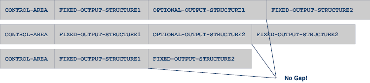
COBOL group data items can be used in a COBOL server program to return optional output similar to the example below;
the returned data is built by copying the necessary COBOL structures into an output area.
The optional output is one of OPTIONAL-OUTPUT-STRUCTURE1, OPTIONAL-OUTPUT-STRUCTURE2 or nothing.
The presence of the optional output is controlled by a structure named CONTROL-AREA.
Optional output with group data items are a variant of MPO,
see Example 5: COBOL Server Using Multiple Possible Output (MPO).
   WORKING-STORAGE SECTION.

   01 INPUT-AREA.
      02 FIX-INPUT-ITEM1                      PIC X(4).
      02 <some fields>                        PIC <clause>.
      . . .

   01 OUTPUT-OFFSET                           PIC  S9(9) BINARY.
   01 OUTPUT-AREA                             PIC X(32000).
      . . .

   01 CONTROL-AREA.
      02 OPTIONAL-OUTPUT                      PIC X(1).
         88 OPTIONAL-OUTPUT-1                 VALUE "1".
         88 OPTIONAL-OUTPUT-2                 VALUE "2".
         88 OPTIONAL-OUTPUT-NONE              VALUE "N".
      . . .

   01 OPTIONAL-OUTPUT-STRUCTURE1.
      02 OPTIONAL-OUTPUT-ITEM11               PIC X(10).
      02 OPTIONAL-OUTPUT-ITEM12               PIC X(100).
      02 OPTIONAL-OUTPUT-ITEM13               PIC X(20).
      . . .

   01 OPTIONAL-OUTPUT-STRUCTURE2.
      02 OPTIONAL-OUTPUT-ITEM21               PIC X(4).
      02 OPTIONAL-OUTPUT-ITEM22               PIC X(50).
      02 OPTIONAL-OUTPUT-ITEM23               PIC X(50).
      . . .

   01 FIX-OUTPUT-STRUCTURE1.
      02 FIX-OUTPUT-ITEM11                    PIC X(4).
      02 FIX-OUTPUT-ITEM12                    PIC X(20).
      02 FIX-OUTPUT-ITEM13                    PIC X(8).
      . . .

   01 FIX-OUTPUT-STRUCTURE2.
      02 FIX-OUTPUT-ITEM21                    PIC X(2).
      02 FIX-OUTPUT-ITEM22                    PIC X(10).
      02 FIX-OUTPUT-ITEM23                    PIC X(10).
      . . .


      IF <some-condition> THEN
         SET OPTIONAL-OUTPUT-1 TO TRUE
      ELSE IF <some-other-condition> THEN
         SET OPTIONAL-OUTPUT-2 TO TRUE
      ELSE
         SET OPTIONAL-OUTPUT-NONE TO TRUE
      END-IF.

      . . .

*     provide control area for optional output
      MOVE 1 TO OUTPUT-OFFSET.
      STRING CONTROL-AREA DELIMITED BY SIZE
      INTO OUTPUT-AREA WITH POINTER OUTPUT-OFFSET.

*     provide data items before optional output
      STRING FIX CONTROL-AREA DELIMITED BY SIZE
      INTO OUTPUT-AREA WITH POINTER OUTPUT-OFFSET.

*     provide optional output
      EVALUATE TRUE
          WHEN OPTIONAL-OUTPUT-1
             STRING OPTIONAL-OUTPUT-STRUCTURE1 DELIMITED BY SIZE
             INTO OUTPUT-AREA WITH POINTER OUTPUT-OFFSET
          WHEN OPTIONAL-OUTPUT-2
             STRING OPTIONAL-OUTPUT-STRUCTURE2 DELIMITED BY SIZE
             INTO OUTPUT-AREA WITH POINTER OUTPUT-OFFSET
      END-EVALUATE.

*     provide data items after optional output
      STRING FIX-OUTPUT-STRUCTURE2 DELIMITED BY SIZE
      INTO OUTPUT-AREA WITH POINTER OUTPUT-OFFSET.
      . . .
COBOL server programs using optional shapes for the output layour are extracted as described under Set Multiple Possible Output (MPO) Structures.