
This document provides information on the Control Panel of SMH for display and edit of the current configuration.
The control panel displays information about the installed SMH packages.
![]() To display the installed SMH packages
To display the installed SMH packages
Select System Management Hub in the navigation frame.
The packages currently installed are displayed both in the navigation frame and in the content frame, as illustrated in the image above.
Similarly, expand Control Panel in the navigation frame to display the control panel packages in both views.
The Common Software AG Infrastructure package provides access to configuration information related to the infrastructure common to all Software AG products.
![]() To display configuration information
To display configuration information
Select System Management Hub > Control Panel > Common Software AG Infrastructure.
Configuration information is displayed in the content frame.
Note:
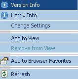
Version information is displayed from the Version Info under the
context menu of SMH infrastructure.
Right-click Common Software AG Infrastructure to open its context menu.
Choose .
Information on the names, types and version numbers of the files associated with the Common Software AG Infrastructure installation are displayed in the content frame.
The System Management Hub package provides access to configuration information related to the SMH installation on the current host machine.
![]() To display the common SMH infrastructure
To display the common SMH infrastructure
Select the System Management Hub node.
Information on the common SMH infrastructure is displayed in the content frame.
![]() To display details on a property
To display details on a property
Choose Details by pressing the question mark
symbol ( ) in the
Details column next to a property.
) in the
Details column next to a property.
Help for that property is displayed in the content frame, as illustrated for the property Language below:
Press Cancel to return to the previous view.
![]() To display version information for SMH
To display version information for SMH
Right-click System Management Hub to open its context menu.
Choose Version Info from the context menu.
Details are displayed in the content frame.
![]() To display installed components
To display installed components
Expand the System Management Hub node to see the installed SMH packages. You can configure each of the displayed components.
This display varies depending on the options selected during the initial installation on the host machine.
The Client/Server and Agent Layer component allows the user to display and configure information related to the Client/Server Layer.
![]() To display client/server layer and agent layer properties
To display client/server layer and agent layer properties
Select the Client/Server and Agent Layer node below the System Management Hub node within the Control Panel in the navigation frame.
Detailed information is displayed in the display view.
![]() To display details on a specific property
To display details on a specific property
Choose Details by pressing the question mark
symbol () in the
Details column next to a property.
Information for that property is displayed in the content frame, as illustrated for the property TCP/IP Queue Size below.
Press Cancel to return to the previous view.
![]() To display the installed plug-ins
To display the installed plug-ins
Right-click the Client/Server and Agent Layer node below the System Management Hub node.
From the context menu choose Plug-in Info.
A table with the installed plug-ins currently installed is displayed in the content frame.
![]() To change the settings of a Client/Server Layer property
To change the settings of a Client/Server Layer property
Right-click the 's context menu and choose Change Settings.
A table with the Client/Server Layer properties is displayed in the content frame.
Make any desired changes in the spaces provided and press to confirm them.
Details on the available options are provided for each property that
is accessible by pressing the question mark symbol ( ) in the Details
column of the table next to each property. The example illustrated below is for
the property TCP/IP Receive Timeout.
) in the Details
column of the table next to each property. The example illustrated below is for
the property TCP/IP Receive Timeout.
Press to return to the previous screen.
This agent is used to add, remove and modify the callback plug-ins in the Client/ Server and Agent Layer.
![]() To display the session plug-ins
To display the session plug-ins
Expand the node in the navigation frame.
The session plug-ins and session agents currently installed are displayed below the node in the navigation frame.
![]() To display details
To display details
Choose Session Plug-ins in the navigation frame.
Information on the session plug-ins is displayed in the content frame.
![]() To add a session plug-in
To add a session plug-in
Open the context menu of the Session Plug-ins node.
Choose from the context menu.
Enter the plug-in name in the space provided. Confirm the library path (or edit it, if necessary, in the dialog box) or press the button to select a different path.
Press to add the new plug-in or to make any changes.
![]() To modify a session plug-in
To modify a session plug-in
Choose from the context menu.
Make the desired modifications in the dialog box and press to confirm those modifications.
Or:
Press the button in the
Command column.
![]() To delete a session plug-in
To delete a session plug-in
Choose from the context menu.
Select the check box next to the session plug-in to be deleted.
Press the button to delete the plug-in or the button to make any changes.
This function is used to add, remove and modify Session Agents in the Client/Server Layer.
![]() To display the session agents
To display the session agents
Expand the node in the navigation frame.
![]() To display details
To display details
Choose Session Agents in the navigation frame.
Information on the session agents and their parameters is displayed in the content frame.
![]() To add a session agent
To add a session agent
Open the context menu of the Session Agents node.
Choose from the context menu.
An input frame similar to the one below requesting the agent's parameters and classpath is displayed.
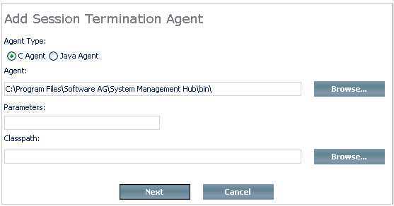
Specify the agent type using the appropriate radio buttons and confirm the agent (or edit it, if necessary, in the dialog box). Enter the parameter and classpath information in the spaces provided.
Press to continue or to make any changes.
Or:
Select a different agent (in the relevant directory) by pressing
the buttons.
After pressing the button in the previous step, a screen similar to the one below is displayed.
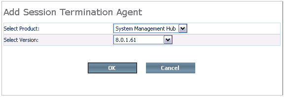
Choose the product and version number from the selection boxes and press to continue.
![]() To modify a Session Agent
To modify a Session Agent
Choose from the context menu.
Make any desired modifications in the dialog box in the content frame and press to confirm those modifications.
![]() To delete a Session Agent
To delete a Session Agent
Choose from the context menu.
Choose the agent to be deleted in the content frame and press to confirm the deletion or to make any changes.
For general information on Agents, see SMH Agents.
The CSLayer server has the option to enable SSX authentication and respectively to manage it.
SSX Configuration is located in the Control Panel node, under the Client/ Server and Agent Layer menu of SMH.
When you click SSX Configuration, the system displays the current SSX properties.
Right-click SSX Configuration to display the system's configuration commands:
Modify SSX configuration;
Enable (Disable) SSX configuration;
Revert last changes.
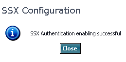
The Enable (Disable) SSX configuration command enables or disables the SSX configuration.
If SSX configuration is successful, you must see the following screen:
The Revert last changes command loads the last configuration. This means that it enables or disables the SSX authentication accordingly.
When you click Modify SSX configuration, a dialog box opens on the right for you to select the authentication type - Active directory, LDAP, or Operating system.
Make your choice and follow the screen's instructions to provide the specific authentication parameters for each authentication type.
For details on the usage of the SSX module in SMH, see Authentication in SMH.
The Events and Job Monitor component allows the user to display and configure information related to the Events Layer.
![]() To display the Events and Job Monitor
To display the Events and Job Monitor
Expand the System Management Hub node below the Control Panel node in the navigation frame and choose Events and Job Monitor Layer.
Detailed information on the properties of the Events Layer is displayed in the content frame.
![]() To display Events and Job Monitor Layer Properties
To display Events and Job Monitor Layer Properties
Open the context menu of the Events and Job Monitor Layer and choose .
Information on the plug-ins currently loaded by the Events Layer is displayed in the content frame.
![]() To display details on a specific property
To display details on a specific property
Choose Details by pressing the question mark
symbol () in the
Details column next to a property.
Information for that property is displayed in the content frame.
Press Cancel to return to the previous view.
![]() To change the current Events and Job Monitor Layer settings
To change the current Events and Job Monitor Layer settings
Open the context menu of the Events and Job Monitor Layer and choose .
The current Events Layer properties are displayed in the content frame.
Make any desired changes in the spaces provided and press to confirm those changes.
Details on the available options are provided for each property,
accessible by pressing the question mark symbol () in the Details
column of the table next to each property. The example illustrated below is for
the property TCP/IP Receive Timeout.
Press to return to the previous screen.
![]() To display details on installed event agents
To display details on installed event agents
Expand the Events and Job Monitor Layer node and choose Event Agent.
Details on the events framework are displayed in the content frame.
![]() To add an event agent
To add an event agent
Open the Event Agent's context menu.
From the context menu choose Add Event Agent.
Specify the agent type using the appropriate radio buttons and confirm the agent (or edit it, if necessary, in the dialog box). Enter the parameter and classpath information in the spaces provided.
Press to continue or to make any changes.
Or:
Select a different agent by pressing the
button. A screen similar to the one below is
displayed.
Choose the product and version number from the selection boxes and press to continue.
![]() To modify an Event Agent
To modify an Event Agent
Choose from the context menu.
Make any desired modifications in the dialog box in the content frame and press to confirm those modifications.
![]() To delete an event agent
To delete an event agent
Choose from the context menu.
Choose the agent to be deleted in the content frame and press to confirm the deletion or to make any changes.
For general information on Agents, see SMH Agents.
The SNMP component allows the user to display and configure information related to the SMH SNMP Layer.
![]() To display information on the SNMP Layer
To display information on the SNMP Layer
Choose the SNMP Layer below the System Management Hub node within the Control Panel in the navigation frame.
Information on the current settings is displayed in the content frame.
![]() To display details on a specific property
To display details on a specific property
Choose Details by pressing the question mark
symbol () in the
Details column next to a property.
Information for that property is displayed in the content frame.
Press Cancel to return to the previous view.
![]() To change the current SNMP Layer settings
To change the current SNMP Layer settings
Open the context menu of the SNMP Layer below the Control Panel node in the navigation frame.
From the context menu choose Change Settings.
The current SNMP Layer properties are displayed in the content frame.
Make any desired changes in the spaces provided and press to confirm them.
Details on the available options are provided for each property
that is accessible by pressing the question mark symbol () in the Details
column of the table next to a property.
Press to return to the previous screen.
The SNMP Notification component allows the user to display and configure the current SMH SNMP notifications.
![]() To display the SNMP Notifications Layer
To display the SNMP Notifications Layer
Expand the SNMP Layer below the Control Panel node in the navigation frame and choose SNMP Notifications.
The current SNMP Notifications are displayed in the content frame.
![]() To add a new SNMP notification
To add a new SNMP notification
Open the context menu of the SNMP Notifications node in the navigation frame.
From the context menu choose Add Notification.
Enter the URL and UDP Port for the new notification in the spaces provided and press to confirm.
![]() To modify an existing SNMP notification
To modify an existing SNMP notification
Open the context menu of the SNMP Notifications node in the navigation frame.
From the context menu choose Modify Notification.
Modify the UDP Port for the notification in the space provided and press to confirm.
![]() To delete an existing SNMP notification
To delete an existing SNMP notification
Open the context menu of the SNMP Notifications node in the navigation frame.
From the context menu choose Delete Notification.
Choose the notification to be deleted and press to confirm.
If you want to use SSL communication you must have a valid key pair – a Certificate file and a Private Key file. This pair is stored in PKCS12 keystore. It must be available before you enable the SSL. SSL support is disabled by default because you must provide a valid keystore first.
Enable SSL using from the menu.
If you do not have a valid keystore, SMH can create it with the Modify wizard of the menu.
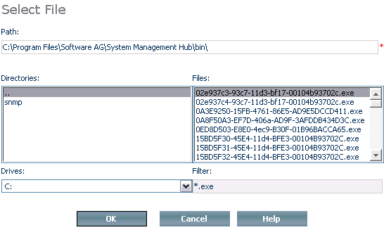
Right-click SSL Configuration from the node and point to Modify.
You can generate a new certificate (PKCS12), upload an existing PKCS12 (PFX) certificate keystore, or use a pair of a private key file and a certificate file in PEM format.
Following is information for server.p12 location:
Windows users: The generated PKCS12 file is stored in {{ARGDIR}}\files as server.p12. {{ARGDIR}} stands for the SMH installation directory. By default, it is Software AG_directory\InstanceManager. The full path is Software AG_directory\InstanceManager\files\server.p12.
UNIX users: The generated PKCS12 file is stored in {{ARGDIR}}/files as server.p12. {{ARGDIR}} stands for the SMH installation directory. By default, it is $SAG/common/arg. The full path is 0.$SAG/common/arg/files/server.p12.
You must provide a password for the keystore to generate a new certificate. The password must be at least 5 characters long. Then, SMH generates a keystore that contains a certificate file and a private key file.
If you want to upload an existing PKCS12 (PFX) keystore, provide the existing password of the keystore and navigate to the location where your existing keystore is located, using the button.
If you want to use a private key file and a certificate file in PEM format, provide the private key file’s password and navigate to the locations where your PEM files are stored in the same way as in the preceding example.
After you complete all the steps, SMH verifies the success of the operations with the following screen:
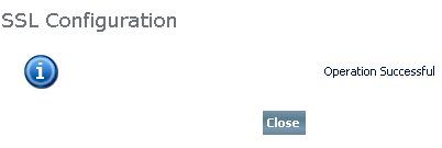
This screen confirms that SSL support is enabled for all the options of the SSL configuration tool..
For general information on SSL, see Secure Sockets Layer (SSL) in SMH.
Users can add tasks, scheduled tasks, and mappings.
The following example of the two ways of executing an automated task is taken from the execution of a sendmail client script (sendmail.cmd, located in C:\Program Files\Software AG\System Management Hub\tasks)
Depending on the location the tasks are called from, you can execute them from two different places.
From the argsrv poller thread; it
checks for any event messages fired during a certain period.
Argsrv is configured in the registry settings:
Default 1 min.
From the in the menu; this provides manual execution of the task (scripts).
Depending on the location from where they are executed, the following sample shows the order of parameters that the agent receives for further processing:
If called from Argsrv poller thread,
then:
Parameter 0 -> The name of the script that is called.
Parameter 1 -> The Task ID from the registry.
Parameter 2 -> The Event Job Token ID. {This event job token ID can be used for further logging into the
                argevt layer infrastructure. The executable argevutl can be used to log and close the events}
Parameter 3 -> The Mapped Message ID within Message mappings for which the script is executed.
Parameter 4 -> The Description of the above message ID.
Parameter 5 -> The Entier task parameters that are sent to the script to execute.
                This parameter simply starts with the substring "TP:TP|" to define that this is the Task parameter
                {NOTE: The parameter syntax expected can be defined by the originator of the task (script).
                       The example provided is of a Send Mail utility which expects the following format for the parameter
                      "TP:TP|To:Benedict.Dsilva@softwareag.com|From:Customer.Support@softwareag.com|
                        CC:Benedict.Dsilva@softwareag.com|Subject: Tamino 4.4.1 Licences (Licence Expired)|
                        Body: Please renew your License. For assistance, call Software AG support center|SMTP:punmsg01"
                 }
Parameter 6 -> The Message parameters, (if any...)
Parameter 7 -> The Message parameters, (if any...)
Parameter . -> The Message parameters, (if any...)
Parameter n -> The Message parameters, (if any...)
If called from Run Tasks GUI Interface, then:
Parameter 0 -> The name of the script which is called.
Parameter 1 -> The Task ID from the registry.
Parameter 2 -> The Event Job Token ID. {This event job token ID can be used for further logging on the
                argevt layer infrastructure. The executable argevutl can be used to log and close the events}
Parameter 3 -> The Entier task parameters which are sent to the script to execute.
                This parameter simply starts with the substring "TP:TP|" to define that this is the Task parameter
                {NOTE: The parameter syntax expected can be defined by the originator of the task/script.
                       The example provided is of a Send Mail utility which expects the following format for the parameter
                       "TP:TP|To:Benedict.Dsilva@softwareag.com|From:Customer.Support@softwareag.com|
                        CC:Benedict.Dsilva@softwareag.com|Subject: Tamino 4.4.1 Licences (Licence Expired)|
                        Body: Please renew your Licence. For assistance, call Software AG support center|SMTP:punmsg01"
                 }
Following is an example if the task (script) is called from the
Argsrv poller thread:
java com.softwareag.systemmanagementhub.emailclient.MailClient %5
Example if called from the interface:
 java com.softwareag.systemmanagementhub.emailclient.MailClient %3

 {NOTE: The MailClient above uses the JavaMail SMTP API to send mails.
        Please include the mail.jar, activation.jar and argjlib.jar (ARGUS internal jar which provides the MailClient
        in the CLASSPATH environment variable
 }
When you start an application from , it is assigned a job token as a parameter. The application must close it before end of execution.
Note:
The job has to be closed from the application that started
it.
Following is a script example:
:CLOSE_JOB_LOG
"%Programfiles%\Software AG\System Management Hub\bin\argevutl.exe" %1 %2 close ARGAA0303 >> %LOGFILE% 2>&1

Usage:  TaskID JobToken Action MessageID [MessageParams]

        TaskID            :   Task ID
        JobToken          :   The Event Job Open Token ID
        Action            :   addmsg | create | close
        MessageID         :   Message ID
        [MessageParams]   :   0..n Number of Message Parameters
Example:
argevutl.exe 0 0 create ARGAA0100 USER_NAME=mickeymouse
argevutl.exe 2 000e74004359ef9e-00 addmsg ARGAA0101 USER_NAME=mickeymouse
argevutl.exe 2 000e74004359ef9e-00 close ARGAA0300

@return   0,1,2
        0 -> Success
        1 -> Usage Error
        2 -> Invalid Token
Following is an example of the usage in case of using a batch file on Windows:
@echo off
 argevutl.exe 0 0 create INOAAI0574 dbName=fake > temp.txt
 FOR /F %%b  in (temp.txt) Do set token=%%b
 argevutl.exe 1 %token% addmsg INODSF1011
 argevutl.exe 1 %token% close
Following is a description of the interface that provides you with the option to execute tasks (scripts) manually:
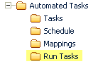
The Automated Tasks Package is used to manage automated task configuration, scheduling, event-job to task mapping and manual execution and scheduling of tasks.
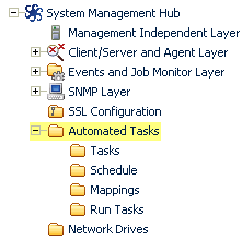
In the navigation frame choose Automated Tasks below System Management Hub under the Control Panel node.
The detail-view frame on the right displays the dashboard for the current configurations and for the mapped and scheduled tasks with the current settings.
The node allows you to automate actions, scheduled tasks and event mappings. It is used to add, remove, and modify tasks configured within the system.
If you want to to access the tasks agent, expand in the tree-view frame by clicking the plus symbol next to it.
Select in the tree-view frame. The tasks currently defined are displayed in the detail-view frame.
![]() To add a new automated task
To add a new automated task
Expand the Automated Tasks node in the navigation frame.
Click .
A input frame requesting the Description, Script, Parameters, Run as User and Password for the script is displayed. The Task ID is automatically generated by the agent.
Provide a description of the new task and enter the parameters associated with it. Your user ID and password are entered as default.
Press the button to confirm your entries. Press the button to make any changes.
![]() To add a new scheduled task
To add a new scheduled task
Expand the Automated Tasks node in the navigation frame.
Choose the Schedule option. A table of the currently scheduled tasks are displayed in the content frame.
Open the context menu for the Schedule option.
In the Schedule option's context menu, choose Add Scheduled Task.
Enter the task ID in the dialog box. Scheduling can be on a daily, weekly or monthly basis. For weekly tasks specify the day of the week on which you wish the task to run. For monthly tasks specify the day of the month. Specify how long you wish the schedule to apply to the task by entering the start and end dates. Set the desired time and check the Scheduled box.
Press the button to confirm your entries. Press the button to make any changes.
![]() To add a new mapping
To add a new mapping
Expand the Automated Tasks node in the navigation frame.
Choose the Mappings option. A table of the message ID to task ID mappings currently defined are displayed in the content frame.
Open the context menu for the Mappings option.
In the Mappings option's context menu, choose Add Mapping.
Enter the message ID from which and the task ID to which the new mapping is to apply in the dialog boxes.
Press the button to confirm your entries. Press the button to make any changes.
![]() To configure the send mail event
To configure the send mail event
Open the context menu of the Mappings option, and choose Add Mapping.
Fill in the screen as shown in the next snapshot. The MessageID should be INODSW2326, which corresponds to the following Tamino message:
<timestamp> INODSW2326: The license for XXXX with ID YYYY has expired, server aborts in ZZZZ days
Note:
Note: if Tamino uses a temporary/evaluation license, the license
check is performed every 24 hours.
Once all of the fields have been filled in, press the button.
On Windows operating systems use the regedit
utility and set the string value AutomatedTasks to
"1". This can also be done directly from the SMH web
interface on both Windows and UNIX.
Restart the Software AG Client/Server Layer services by selecting it from the Services screen and choosing the Restart option, as illustrated in the screen capture below.
The Network Drives configuration is only available on Windows.
The Network Drives component allows the user to display and configure the network drives mapping available to the products managed by SMH.
![]() To display network drives
To display network drives
In the navigation frame, choose the Network Drives node.
Information on all networked drives is displayed in the content frame.
The contents of all SMH tables can be sorted in a variety of ways. See the section on how to sort the information in a table, above, for more details.
![]() To display the details of an existing network drive mapping
To display the details of an existing network drive mapping
In the appropriate Action column of the content frame, choose in the row of the drive you wish to display.
![]() To modify an existing network drive mapping
To modify an existing network drive mapping
In the appropriate Action column of the content frame, choose in the row of the drive you wish to modify.
Make the desired changes and press the button to confirm. For more information on how to modify a drive, make sure that you have pop-ups enabled in your browser and press the button.
![]() To disconnect an existing network drive mapping
To disconnect an existing network drive mapping
In the appropriate Action column of the content frame, choose in the row of the drive you wish to disconnect.
Press the button to confirm. Press the button to return to the previous display.
![]() To map a new network drive
To map a new network drive
In the navigation frame, open the context menu of the Network Drives node.
From the Network Drives context menu, choose Map Drive.
The Map Drive screen is displayed in the content frame.
Enter the drive letter without a colon ( : ). Enter the name of the folder (in the format \\DOMAIN\DRIVE). Your user identification and password are entered in the appropriate dialog boxes by default.
Press the button to map the new drive. Press the button to return to the previous display. For more information on how to map a network drive, make sure that you have pop-ups enabled in your browser and press the button.
The contents of the table of network drives can be sorted. See the section on how to sort the information in a table, above, for more details.