
A single ApplinX screen represents a corresponding screen in the host. An
ApplinX screen is usually defined using unique text identifiers from the host
screen but it is also possible to use other identifiers such as the position of
the cursor when the screen is loaded or field attributes (Protected,
Intensified or Hidden). When navigating in the host application, ApplinX tries
to find the screen entity that matches the host screen it encounters. Once a
match is found, ApplinX can use the data and definitions of the host screen in
its various components. Sometimes the screen image needs to be updated, click
on the Capture image icon ![]() to
update the image. The following guidelines will help you determine which
screens to identify:
to
update the image. The following guidelines will help you determine which
screens to identify:
Screens that will be customized in a Web application (will be generated as web pages) as ApplinX uses identified screens to correctly load the customized Web page.
Screens that will be part of navigation paths (recommended for easier path definition).
Screens that will contain application field mappings.
Any important screen in the host application.
In this section we will cover:
To allow the ApplinX Server to recognize the corresponding host screen; each screen must be identified by giving it a unique name, and defining the screen's identifiers. In addition, when relevant, you may want to map fields to the screen, apply transformations to the screen, define screen based tables, associate screen groups to the screen and define steps in the application map.
ApplinX screens can be created manually, via the Session View (Create a New Screen using the Session View), by importing application host maps such as Natural, BMS and MFS (Importing an Application's Maps), or automatically or semi-automatically, using identification definitions (Changing the Screen Definition Mode).
Creating Screens via the Session View
Using Screen Creation Definitions: Screens can be identified and created quickly using general screen creation definitions.
Using Screen Creation Definitions: Manually: The New Screen wizard is displayed when clicking on the icon. Manual identification can be used with or without Screen Creation Definitions.
Using Screen Creation Definitions: Semi-automatically: The New Screen wizard will automatically be displayed for each unknown screen that matches a Screen Creation Definition. This screen will include basic screen definitions, which are defined in the Screen Creation Definition.
Using Screen Creation Definitions: Automatically: A screen will automatically be created for each unknown screen that matches a Screen Creation Definition. This screen will include basic screen definitions, which are defined in the Screen Group.
Automatically identify screens using the Trace Files (GCT) wizard
Screens can be created via the menu or from within the session view.
Note:
The screen must be displayed in the session view when creating the
new screen.
 To create a screen via a session:
In the Emulation session, navigate to the relevant screen.
Select text in the emulation screen.
Click on the Identify Screen button
![]() . The New Screen wizard is
displayed, with a suggested name displayed in the Name field. Enter a suitable
description and determine the folder where the screen is to be located. Click
. You have now created a new screen entity in the
repository.
. The New Screen wizard is
displayed, with a suggested name displayed in the Name field. Enter a suitable
description and determine the folder where the screen is to be located. Click
. You have now created a new screen entity in the
repository.
For the ApplinX Server to recognize a host screen, you need to identify the screen in ApplinX. The screen is identified using "identifiers". Different identifier types include identifying specific text on the screen, the screen cursor position or the field attributes. The ApplinX Server analyzes the current screen and tries to match it to all of the screen identification strings stored in the application repository (database). For a screen to be recognized, all its identifiers must be matched. You may define an unlimited number of identifiers.
Text Identifiers: Use text identifiers to identify a screen by selecting specific text that appears on the screen. Use the Capture from Screen feature to identify a string of text accurately from the host screen and insert this string into the text box.
To define a text identifier:
Access the relevant screen.
Select the Identifiers Tab.
Determine whether to ignore the application's window definitions during the identification of a screen, select the relevant check box. Once the screen is identified the full screen is used. This check box is only enabled when the screen has a window.
Note:
When changing the state of the Ignore entire screen
(ignore window definition) check box, you must manually edit the
identifiers and mappings to support the new positions.
Click the arrow on Add Identifier and select . Another row will be added to the list of identifiers.
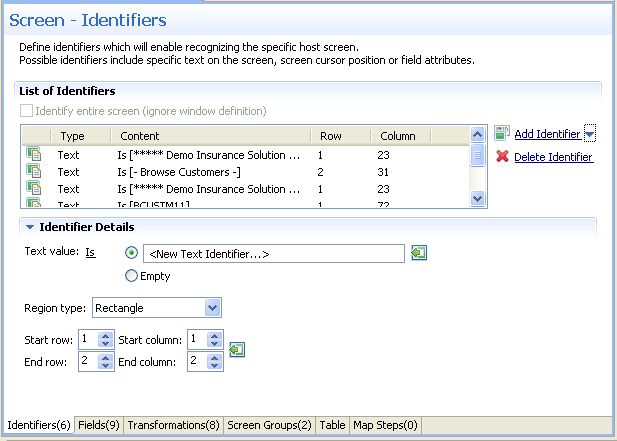
Select Is (default) in order to match the exact text on the host screen. Alternatively, select Is NOT if any text other than the specified is suitable as a screen identifier. Check Empty to identify an empty space on the host screen. This clears the Text text box.
Select Rectangle to indicate that the identifier should be searched for within the defined rectangle, Position, to indicate that the identifier must start at a specific position or Anywhere on screen to indicate that the identifier may be anywhere on the screen.
When selecting Rectangle, define the rectangle range (start and end row and column.). When selecting Position, select the row and column.
It is also possible to add an identifier by selecting the area in the host screen, and then clicking Add Identifier. When selecting an area which is a rectangle, identifiers will be added for each and every row of the selected rectangle.
Cursor Position Identifiers:Use the Cursor Position identifier to identify a screen by the cursor position when the screen is loaded.
To define a cursor position identifier:
Access the relevant screen.
Select the Identifiers Tab.
To ignore the application's window definitions during the identification of a screen, select the relevant check box. Once the screen is identified the full screen is used.
Click the arrow on Add Identifier and select . Another row will be added to the list of identifiers.
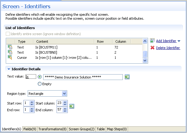
Select Is to indicate that the cursor is positioned within the region area details that follow. Alternatively, selectIs NOT to indicate that the cursor is not positioned within the region area details that follow.
Select Rectangle to indicate that the cursor position should be searched for within the defined rectangle or Position, to indicate that the cursor position must start at a specific position
It is also possible to add an identifier by selecting the area in the host screen, and then clicking Add Identifier.
Attribute Identifiers:Use the Attributes identifier to identify a screen by the host's attributes. Attributes of the host screen may be Protected, Intensified or Hidden.
To define an attribute identifier:
Access the relevant screen.
Select the Identifiers Tab.
To ignore the application's window definitions during the identification of a screen, select the relevant check box. Once the screen is identified the full screen is used.
Note:
When changing the state of the Ignore entire screen
(ignore window definition) check box, you must manually edit the
identifiers and mappings to support the new positions.
Click the arrow on Add Identifier and select . Another row will be added to the list of identifiers.
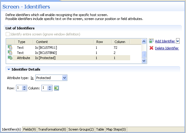
Select whether the Attribute Type is/is not Protected, Hidden, Intensified or Reversed video.
Enter values or use the Capture from Screen feature to indicate a specific location of the attribute by its Row and Column.
It is also possible to add an identifier by selecting the area in the host screen, and then clicking Add Identifier.
Window Identifiers:Use the Window identifier to identify a screen by determining whether it is or is not a window. In Natural UNIX, it is possible to identify a screen by determining whether it is a window and whether it has specific text in the title.
To define a window identifier:
Access the relevant screen.
Select the Identifiers Tab.
To ignore the application's window definitions during the identification of a screen, select the relevant check box. Once the screen is identified the full screen is used.
Click the arrow on Add Identifier and select . Another row will be added to the list of identifiers.
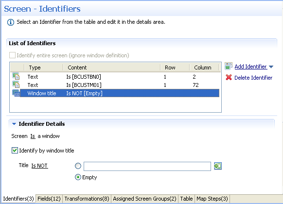
Select Is to indicate that the screen is a window. Alternatively, select Is NOT to indicate that the screen is not a window.
For Natural UNIX hosts: Select the check box to indicate to identify by the window title. You can enter text for the title or select the text in the session view and click the Capture from screen icon. You can also identify a screen which is a window and does not have a title by selecting the Empty radio button.
When a screen is identified, field entities can be mapped to it. A field makes relating to a string on the host screen much simpler. Fields offer an enhanced way of referring to host fields - by their name rather than by their position. In addition, mapped application fields simplify future application maintenance - when a field changes in the original host application, updates only need to be made to the application field definition. The following guidelines will help you determine which fields to identify:
Fields that will be referenced in code (when binding Web page controls to host fields by name).
Fields that will be part of navigation paths.
Fields that will be used as Procedure input and output attributes to expose host transactions as Web services.
Fields that will be used when creating generated Web tables.
Recommended: all input and output fields (not constants).
Any important field in the host application.
An application field makes relating to a string on the host screen much simpler. Fields offer an enhanced way of referencing host fields - by their name rather than by their position. Using fields has many advantages:
A field's ID is meaningful regarding the contents of the field, unlike a numeric position.
You define a field only once, and later can reference that definition in all of your code - knowing you always mean the same definition.
If changes in the host application occur in the future, the only place that requires to be changed is the field definition.
Field properties can be accessed by right-clicking on the Repository node and selecting and then searching for the specific field.
In the Field Editor, it is possible to set the Input Mask (Defines the values that can be entered in the field) and the field type (numeric or alphanumeric).
An input mask consists of literal characters along with special characters that together determine the value that may be entered into input fields. When a user defines a mask on an input field, client side validation will be carried out on the input format. Common usage is in date/time and number or currency fields.
To implement this feature you must change the web application
configuration in the configuration editor:
Open a new browser and run your Web application.
Click on the Configuration link. The Configuration Editor will be displayed.
In the Instant node select the Reflect emulation behavior check box.
The following table shows some useful input mask definitions and examples of values you can enter. Refer to Valid input Characters for details on the codes used to create input mask definitions.
| Input Mask Definition | Example Values |
|---|---|
| (000) 000-0000 | (206) 555-0248 |
| (999) 999-9999 |
(206) 555-0248 ( ) 555-0248 |
| (000) AAA-AAAA | (206) 555-TELE |
| #999 |
-20 2000 |
| >L????L?000L0 |
GREENGR339M3 MAY R 452B7 |
| 00000-9999 |
98115- 98115-3007 |
| L?????????????? |
Maria pierre |
| ISBN 0-&&&&&&&&&-0 |
ISBN 1-55615-507-7 ISBN 0-13-964262-5 |
ApplinX interprets characters in the Input Mask property definition as shown in the following table. To define a literal character, enter any character other than those shown in the table, including spaces and symbols. To define one of the following characters as a literal character, precede that character with a "\".
| Character | Description |
|---|---|
| 0 | Digit (0 through 9, entry required; plus [+] and minus [-] signs not allowed). |
| 9 | Digit or space (entry not required; plus and minus signs not allowed). |
| # | Digit or space (entry not required; blank positions converted to spaces, plus and minus signs allowed). |
| L | Letter (alphabetic, entry required). |
| ? | Letter (alphabetic, entry optional). |
| A | Letter or digit (entry required). |
| a | Letter or digit (entry required). |
| & | Any character or a space (entry required). |
| C | Any character or a space (entry optional). |
| \ | Causes the character that follows to be displayed as a literal character. Frequently displayed any of the characters listed in this table as literal characters (for example, \A is displayed as just A). |
When a screen is identified, field entities can be mapped to it. A field makes relating to a string on the host screen much simpler. Fields offer an enhanced way of referring to host fields - by their name rather than by their position. In addition, mapped application fields simplify future application maintenance - when a field changes in the original host application, updates only need to be made to the application field definition. The following guidelines will help you determine which fields to identify:
Fields that will be referenced in code (when binding Web page controls to host fields by name).
Fields that will be part of Path Procedures.
Fields that will be used as Procedure input and output attributes to expose host transactions as Web services.
Fields that will be used within tables.
Recommended: all input and output fields (not constants).
Any important field in the host application.
There are limitations when defining a mapping. A mapping cannot:
Start in an unprotected field and end in a protected field, or vice versa.
Start with an attribute byte.
Overlap another mapping on the same screen.
Start in one line and end on another line.
Start on one line and end off the screen's limits.
Fields can be mapped according to their position in the screen or according to their leading label - dynamic field mapping (do not set the same field to be mapped by position and by its leading label).
Mapping according to leading labels (dynamic mapping) is particularly useful in the following cases:
The application has fields that are dynamically drawn on the screen.
Host applications are sometimes changed and items can be moved. Using dynamic field mappings, the fields will continue to be mapped and identified and the application will not be affected.
Using dynamic field mappings enables more flexibility when using Screen Groups, as Screens which include the same field, can be associated with the same Screen Group even when the field is located in a different position.
To map application fields according to their position in the
screen:
Click the Fields tab to view and/or modify the application fields in this screen.
Click the arrow next to , and select or to add a new field mapping.
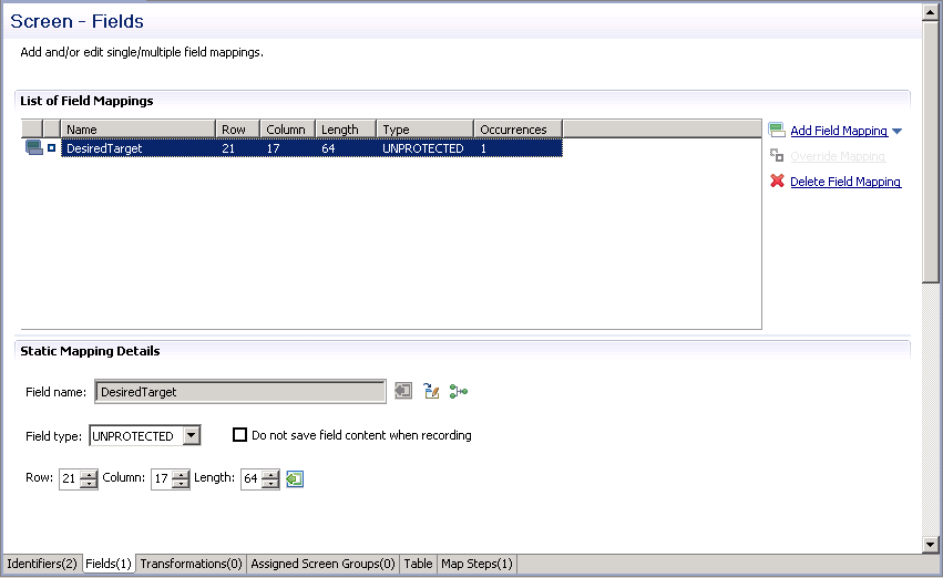
In the Field name field, either enter a field name or enter the first letters of a field name and then click CTRL and SPACE to display relevant fields.
Select the Protection type: Protected (cannot be edited in host), Unprotected (editable in host) or Both (may sometimes be editable and sometimes not).
The Do not save field content when recording check box enables not saving data which you do not want to be displayed when viewing the recorded trace file.
The Row and Column fields indicate the position of the field on the screen. The values of these fields can be changed using the Capture from Screen feature or by entering values in the fields.
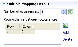
When adding a multiple field mapping, determine the number of occurrences and the rows and/or columns between occurrences.
Note:
You can automatically map all of the unprotected fields in the
screen by clicking on the Automatically identify unprotected
fields icon.
To map application fields according to their leading label (not
available in right to left and character mode applications):
In some screens, the position of a field may vary. It is therefore necessary to map some fields in such a way, that even if they appear in a different position, they will still be recognized and mapped. This is possible by defining the label near the field (the label must be to the left of the field) and identifying the field according to this label. This mapping type is called "Single Dynamic" as the mapping position changes dynamically according to the leading label. Refer to Dynamic Field Mapping Limitations.
Click the Fields tab to view and/or modify the application fields in this screen.
Click the arrow next to Add Field Mapping, and select to add a new field mapping.
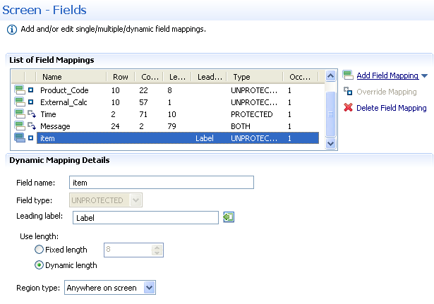
In the Field name field, either enter a field name or enter the first letters of a field name and then click CTRL and SPACE to display relevant fields.
Select the field protection type: Unprotected, Protected or Both. Prefer to set the field type either as Protected or Unprotected when you are sure of the type of the dynamic field. Use Both when you are not sure of the type of the dynamic field.
Determine the leading label: the leading label is the label which appears before the field. This label is inserted as the Field name and can be edited. The label you define should be as accurate as possible (do not use strings which normally appear within the field).
Determine the method to use to search for the label:
Contains text: Searches for the given text anyway in the defined region (default).
Exact phrase: Searches for the given text within the defined region. The text must be preceded and followed by at least two white space characters.
Contains word: Searches for the given text as word(s) within the defined region.
Regular expression: Searches for the given pattern within the defined region. Refer to Regular Expression Syntax.
Note:
When selecting a different option, after defining a regular
expression search definition, the value of the previous regular expression
definition will be lost.
Define the region type in which the label will be searched for: anywhere in the screen, within a specified rectangle or within a specified row range. The Row and Column fields indicate the position of the label on the screen. The values of these fields can be changed using the Capture from Screen feature or by entering values in the fields.
Use length:
In Unprotected fields: Determine whether to recognize a field mapping according to the leading label and the length of the input field (Fixed length) or just according to the leading label (Dynamic length).
In Protected fields: The length defined here is the length of the mapping. The identified field is cropped to the specified length.
Define the region type in which the field will be searched for: anywhere in the screen, within a specified rectangle or within a specified row range. The Row and Column fields indicate the position of the field on the screen. The values of these fields can be changed using the Capture from Screen feature or by entering values in the fields.
Note:
The region will be displayed in the Session View with a yellow
frame, and the background of the screen within this region will be
dotted.
It is preferable to define your regions as rectangles, that do not overlap each other, and whose size are minimal.
The feature is best suited to locate dynamic fields which change their location vertically so that labels are aligned vertically in one region, and fields aligned vertically on a region to the right of the labels.
Mappings inherited from screen groups
Mappings inherited from screen groups are indicated with an icon.
You can override this mapping to suit the current screen by clicking on the
Override hyperlink. Hereafter, this mapping will be marked
with the ![]() icon. You can
restore the inherited mapping by clicking on the Restore Inherited
Mapping hyperlink. Note that when selecting an inherited mapping, it
is not possible to change the mapping properties. When selecting a local
mapping, all properties can be changed. When selecting an overridden mapping,
all properties can be changed, except for the name.
icon. You can
restore the inherited mapping by clicking on the Restore Inherited
Mapping hyperlink. Note that when selecting an inherited mapping, it
is not possible to change the mapping properties. When selecting a local
mapping, all properties can be changed. When selecting an overridden mapping,
all properties can be changed, except for the name.
To delete a field mapping, click on the Delete Field Mapping hyperlink.
Note:
It is not possible to remove mappings which are used in other
entities, such as in procedures, transformations or tables.
You can sort the contents of a List of Field Mappings table by field name or by any other column. Click the header of the column by which you want to sort. The contents are sorted in ascending order. Click again to sort in descending order. This feature is useful when detecting duplicate field entries. The sort will be cancelled when you close the screen entity.
VT parameters are defined per application. Sometimes it is necessary to override these parameters for a specific field, for example when it is necessary to define that a field is a password type field. this means that characters are sent from applinX to the host, but only asterisks are retrieved from the host. in order to validate that the correct data has been received from the host, it needs to be indicated that this field's characters are hidden. This option is selected in the by opening the relevant screen in the Editor view and in the Fields tab, changing the VT Parameter's configuration (in the Host field behavior field). Additional parameters can also be configured here. Refer to Fields tab: VT Parameters section.
Screen Creation Definitions are a set of basic definitions which are used to create a new ApplinX screen. These definitions include the default screen name, initial identifiers and determine whether input fields will be created. Creating a new screen using screen creation definitions reduces the complexity and the time required to identify new screens.
To use this feature, at least one set of Screen Creation Definitions must be created within a Screen Group (in the dedicated tab). When navigating within a session, and reaching an unidentified screen, ApplinX searches for Screen Groups which match the unidentified screen, and then creates a new screen based on the screen group's identifiers and on parameters defined in the creation definition configured in the Screen Group. This process can be initiated in three different modes:
Automatically: A screen will automatically be created for each unknown screen that matches a screen group. This screen will include basic screen definitions, which are defined in the screen group.
Semi-automatically: The New Screen Wizard will automatically be displayed for each unknown screen that suits a screen group. This screen will include basic screen definitions, which are defined in the screen group.
Manually: The New Screen Wizard is displayed when clicking on the Identify New Screen icon.
The mode is set in the session view by clicking on the Change screen creation mode icon in the tool bar. Refer to Changing the Screen Definition Mode.
The difference between creating a screen in the manual mode and creating a screen in the semi-automatic mode, is that in the manual mode, when you reach an unidentified screen, you are required to click on the Identify New Screen icon in the Session view. You can then select from a list of Screen Groups relevant to this screen, the screen group which has screen creation definitions which you would like to use (you can select to create a new screen without using screen creation definitions by clicking on in the Use a Screen Creation Definition dialog box). By default the list of screen groups which are relevant to this screen are displayed. It is also possible to show and select a screen group from all the application screen groups that have screen creation definitions. If you want ApplinX to always use the Screen Group with the highest priority, select the Don't ask again check box. It is possible to display this dialog box again by changing the Always use the highest prioritized screen group check box in .
The new screen has a number of basic definitions such as the screen name and a number of identifiers. These are determined according to the definitions in the Screen Creation Definition tab in the relevant Screen Group entity (You can select to create a new screen without using screen creation definitions by clicking on in the Use a Screen Creation Definition dialog box). The screen name is determined according to the screen name position definition in the Screen Creation Definition tab. The list of identifiers is determined according to the Screen Group identifiers, as well as the strings which appear in the list of identifier locations in the Screen Creation Definition tab. To automatically create input fields in the new screen, select Automatically create input fields. The labels near the input fields are used as the input field names.
To manually create screens using screen creation definitions
Within the relevant Screen Group, create a Screen Creation Definition.
Ensure that in the session view the selected mode is Manual Screen Creation: in the Session view click on the Screen Creation Definition mode icon and select Manual Screen Creation.
Navigate within a session.
Once a screen group is recognized within an UNKNOWN screen, click on the Identify New Screen icon. The Use a Screen Creation Definition dialog box is displayed. Here you can determine whether to base the new screen on a Screen Creation Definition or not. Click to create a new screen without using Screen Creation Definitions.
This dialog box displays, by default, the screen groups which have screen creation definitions and are relevant to the UNKNOWN screen. You can display all the screen groups which have screen creation definitions and select a different screen group. Click
The New Screen wizard is displayed. The default name is taken from the text which appears in the screen name position definition in the Screen Creation Definition tab. Click
The new screen is displayed in the Editor and is listed in the repository.
Refer to Automatically Creating Screens .
Refer to Semi-Automatic Creation of Screens.
Similar to the automatic mode, when navigating in a session and a screen group is recognized, and the current screen has not yet been identified, the process of creating a new screen entity is initiated. The new screen has a number of basic definitions such as the screen name and a number of identifiers. These are determined according to the definitions in the Screen Creation Definition tab in the relevant Screen Group entity (You can select to create a new screen without using screen creation definitions by clicking on in the Use a Screen Creation Definition dialog box). The screen name is determined according to the screen name position definition in the Screen Creation Definition tab. The list of identifiers is determined according to the Screen Group identifiers, as well as the strings which appear in the list of identifier locations in the Screen Creation Definition tab. To automatically create input fields in the new screen, select Automatically create input fields. The labels near the input fields are used as the input field names. As there may be more than one Screen Group which has Screen Creation Definitions, it is necessary to determine which screen group is to be used. This is done in the Use a Screen Creation Definition dialog box which is displayed once the unknown screen is reached. By default the list of screen groups which are relevant to this screen are displayed. It is also possible to show and select a screen group from all the application screen groups that have screen creation definitions. If you want ApplinX to always use the Screen Group with the highest priority, select the Don't ask again check box. It is possible to display this dialog box again by changing the Always use the highest prioritized screen group check box in .
To semi-automatically create screens using screen creation
definitions
Within the relevant Screen Group, create a Screen Creation Definition.
Ensure that in the session view the selected mode is : in the Session view click on the mode icon and select .
Navigate within a session.
Once a screen group is recognized within an unidentified screen, the Use a Screen Creation Definition dialog box is displayed. Here you can determine whether to base the new screen on a Screen Creation Definition or not. Click to create a new screen without using Screen Creation Definitions.
This dialog box displays, by default, the screen groups which have screen creation definitions and are relevant to the UNKNOWN screen. You can display all the screen groups which have screen creation definitions and select a different screen group. Click .
The New Screen wizard is displayed. The default name is taken from the text which appears in the screen name position definition in the Screen Creation Definition tab. Click
The new screen is displayed in the Editor and is listed in the repository.
Refer to Automatically Creating Screens .
Refer to Manually Creating Screens.
When navigating to an unidentified (UNKNOWN) screen in a session and a screen group is recognized, a new screen entity is created. The new screen has a number of basic definitions such as the screen name and a number of identifiers. These are determined according to the definitions in the Screen Creation Definition tab in the relevant Screen Group entity. The screen name is determined according to the screen name position definition in the Screen Creation Definition tab. The list of identifiers is determined according to the Screen Group identifiers, as well as the strings which appear in the list of identifier locations in the Screen Creation Definition tab. When more than one screen group is relevant to the screen, the screen creation definition is based on the definition in the screen group with the highest priority. To automatically create input fields in the new screen, select Automatically create input fields. The labels near the input fields are used as the input field names.
To automatically create screens using screen creation
definitions
Within the relevant Screen Group, create a Screen Creation Definition.
Ensure that in the session view the selected mode is Automatic Screen Creation: in the Session view click on the icon and select .
Navigate within a session. New screens are automatically added to the repository.
Refer to Semi-Automatic Creation of Screens.
Refer to Manually Creating Screens.
Using trace (GCT) files, you can automatically identify screens. In order to do this, you must ensure that a Screen Group includes a Screen Creation Definition.
To automatically identify screens using trace files:
Right-click on the relevant application, and select. The wizard is displayed.
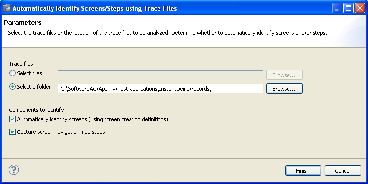
Select whether to analyze files or a folder. Locate the files/folder.
Select the Automatically identify screens check box.
You can automatically identify steps by selecting the Capture screen navigation map steps check box. Refer to Automatically Identify Steps using Trace Files (GCT) for further details.
Click .
The Console displays the outcome of the process.
Note:
When identifying a new screen, the screen name is taken from the
area you defined in the Screen Creation Definitions. If a screen with this name
already exits, the newly identified screen's name will be the name as of the
existing screen followed by an incremental number. If the area you defined in
the Screen Creation Definitions is empty, the screen will be named: "Screen"
and then an incremental number.
Standard maps, such as Natural, BMS and MFS, are used in host applications to describe the structure of the host screen including the static text and input and output fields. ApplinX enables importing these application maps, saving time and effort spent on manually identifying screens and simplifying the maintenance process when changes are made in the host application. When importing application maps, a screen is automatically created from each map, minimizing errors that may occur when creating the screens manually, one by one. The ApplinX screen created includes identifiers (based on the static text in the map) and fields (based on the input and output fields in the map). ApplinX supports a number of different types of maps:
NATURAL: Natural map support (from SYSTRANS/SYSOBJH or NaturalONE files).
BMS: CICS basic map support.
MFS: IMS message format service.
SDFX: ApplinX generic map format, used for other standard maps. To create SDFX files refer to SDFX File Format Definition.
SDF: Compatible with Software AG's JIS product.
The import map feature can be used to import an application's maps for a new application or to maintain and update previously imported maps. When updating previously imported maps, screen identifiers will be deleted and replaced, existing fields will be updated with their new positions and their references to other entities will be preserved. Fields that were previously imported, but no longer exist on the host will be deleted.
Note:
Invalid entity names, such as names which include invalid characters
such as "#" or begin with a digit, will be automatically corrected by omitting
the invalid characters.
Note:
The colors displayed in the screen image may sometimes be different
than the colors that are displayed in the original host screen.
Maps can be imported either using the Import Host Screen Maps wizard or using a batch file (screen_import.bat in Windows and screen_import.sh in UNIX).
To import maps using the Import Host Screen Maps wizard
Ensure that the relevant ApplinX application and that the relevant map files are available.
From the menu, select or right-click on the repository node in the relevant application and then select .
The Import Host Screen Maps wizard is displayed.
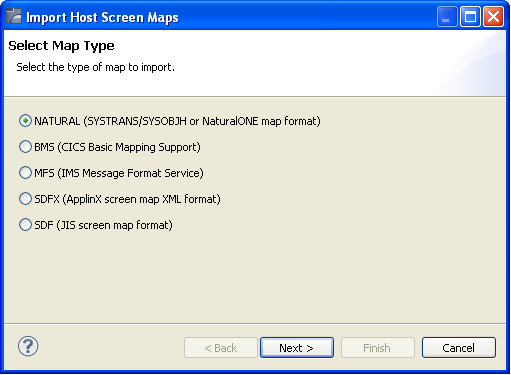
Select the type of map that is to be imported. Click
The Import Parameters screen is displayed.
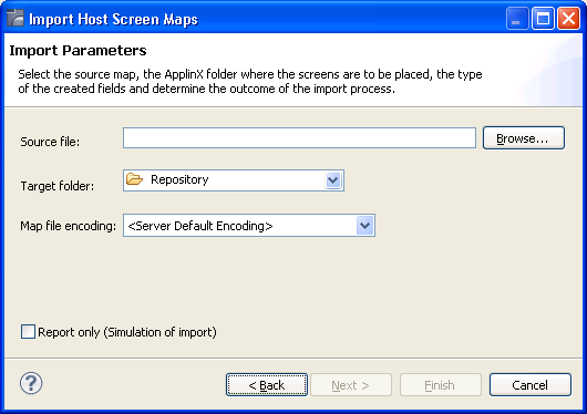
Select the source map file/s that you wish to import.
Select the ApplinX repository folder where the newly created screens are to be placed.
Select the map file encoding. By default, the server operating system default encoding is used.
Note:
When importing maps from NaturalONE it is recommended to use
UTF-8 encoding.
Determine whether you wish to simulate the import process, and create a report which details the import process or whether to actually import the maps and create the screens as well as the report.
If you selected to import a Natural map, you can click to configure the NATURAL Import Parameters, otherwise click to complete the wizard.
NATURAL Import Parameters screen:
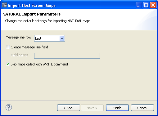
- Message line row
Indicates where the error line is located - in the first line, one, two, three or four lines from the bottom or in the last line.
- Create message line field
Selecting this will map a field in every screen, where a message can be displayed. When selecting this option, you are required to enter a name for the field.
- Skip maps called with WRITE command
Select this in order not to generate maps that are called with the NATURAL WRITE command.
Click .
The screens created appear in the directory you determined in the Target folder field. The names of the screens are identical to the map names.
The report is displayed in the Eclipse console and includes a list of the screens added as well as the fields and identifiers created/updated/deleted.
To import screens via a batch file (using the command prompt
window):
Open a command prompt window.
Change the current directory to the ApplinX home directory.
Type screen_import.bat/sh followed by your required parameters. (The minus sign and letter should precede the value to distinguish between the parameters. The order of the parameters is not significant.)
| Parameter | Description | Default |
|---|---|---|
| -a | ApplinX application name (Required parameter) | |
| -af | ApplinX target folder within the application repository. | Root folder |
| -mf | Message line field name (Natural maps only) | MessageLine |
| -k | Don't skip map with write command. (Natural maps only) | true (skip) |
| -e | Map file encoding: Includes all encodings which
are supported by Java.
Note: |
Server operating system default encoding |
| -f | File name, or directory name (when importing more than one file). Required parameter. | |
| -t | Map type. Possible values: "sdf", "sdfx", "natural", "bms", "mfs" (required parameter). | natural |
| -s | Server address | 127.0.0.1 |
| -m | Indicates where the error line is located: "first", "last", "lastm1" (last minus 1), "lastm2", "lastm3", "lastm4" (Natural maps only) | last |
| -p | Server port | 2323 |
| -u | ApplinX user name (Required parameter) | |
| -x | The file extension. All files from the given directory that have this extension will be loaded (when not specified, the default extension for the map type is used: ".sdf", ".sdfx", ".ncd" or ".nsm"(for Natural), ".bms", and ".mfs"). When a file name is provided (and not a directory), the specific file will be imported (this parameter is not required in this case). | |
| -w | ApplinX user password | Empty by default |
The screens created appear in the directory you determined in the Target folder field. The names of the screens are identical to the map names.
The report is displayed in the command window and includes a list of the screens added as well as the fields and identifiers created/updated/deleted.
Refer to the Application Map for details about the application map. In this tab it is possible to manually define additional steps between screens that already exist in the application map. The steps should be defined in the source screen and determine the destination screen of the step. It is possible to add a simple step between screens or to add an inner path step which executes a path. When you add a simple step, determine the target screen, the key to be sent, and the relevant inputs. When defining an inner path, select the path. Change the status of the step using the links (Approve, Set to Pending, Set to Not Approved). Once you save the new steps, you can check these navigation definitions in the Session View using the Application Map toolbar. Simply select the screen you want to navigate to and click on the Go icon to attempt to navigate to that screen.
A screen based table represents a logical table based on data gathered from a single ApplinX screen. When creating a table you can configure:
The header: A rectangle that contains all the column headers, and will later be used in the framework to hide this area.
Filters: empty row, and duplicate row filters will filter the table according to the value defined in the Primary Key column.
Table Columns: Includes the table definitions such as column details, occurrences, primary keys etc.
Once defined, you may view and design a table in an ApplinX Web application, or access it through a designated API in the ApplinX Base Object or from the Path Procedure Screen Mapper.
To create a table:
Access the relevant screen and click on the Tables tab.
Click on the Create a New Table link.
A default name (new_table), which you can edit will appear in the Table name field.
The header definition is filled with values.
All the multiple fields which are in the screen are added to the list of columns.
Ensure that you check and refine the table definitions as required:
Header: To change the default header definitions, select the header area in the preview of the host screen and then click on the icon that is displayed next to the header row and column fields.
Filter rows: There are two types of filters which can be defined: filtering of empty rows (rows in which the values of the primary key columns are empty) and filtering of duplicated rows (rows in which the values of the primary key columns are identical to those of a previous row). By default these checkboxes are not selected.
Remove, add or edit table columns:
In the Name field enter a logical name to use when programming using the API or the framework, in the Caption field enter the name of the column as it will appear in the Web application, and in the Mapped to field select the host field to which the column will point.
Use the Move Up and Move Down options to define the order of the columns.
Define the table's primary key. A primary key is a key in the table that uniquely identifies each record. A table must always have one and only one primary key. The primary key can consist of one column or a combination of several columns, whose values give a unique key of each record. If no column is defined as the primary key of the table while creating the table, ApplinX automatically creates a numeric primary key for each record.
To define a primary key, select the relevant column and click on the Define Primary Key link.
A screen that belongs to a group inherits all the application field mappings that are mapped to the group.
To associate screen groups to a screen
Access the relevant screen and click on the Assigned Screen Groups tab. The list of Screen Groups currently associated with this screen are listed.
Click on Assign Screen Group to select additional screen groups to be associated with this screen.
This tab is only displayed in right-to-left applications and enables overriding application settings per a specific screen.
VT parameters are defined per application. Sometimes it is necessary to override these parameters for a specific screen. This can be implemented by opening the relevant screen in the Editor view and in the VT parameters tab, changing the configuration. The description of each of these parameters is included in the description of the VT application parameters: VT Application parameters.
Note:
This is not available when working with a SOA license.
The Transformations tab lists the transformations used in the screen. Next to each transformation, an icon indicates whether the transformation is inherited from a screen group, whether the transformation has been defined locally for the current screen, or whether the transformation was originally inherited from a screen group but has been disabled for the current screen.
The Add Transformation Mapping hyperlink enables associating a predefined transformation with this screen. The Delete Transformation hyperlink removes the transformation from the list.
The Enable/Disable icon allows you to determine whether to use the selected inherited transformation or not. The Edit icon enables defining the region relevant to the transformation. The Add icon enables associating a predefined transformation with this screen. The Delete icon (enabled on when selecting a local transformation) removes the transformation from the list.
To apply a transformation to a screen:
In the relevant screen, click on the Transformations tab.
Click the Add Transformation Mapping link to add a transformation.
Select the transformation from the drop-down list of transformations or click on the button to create a new transformation.
Select the relevant screen area: "Anywhere on the screen", "Application fields" (it is mandatory to select a field once this option has been selected) or "Rectangle" and define the region parameters as necessary.
You can display an HTML preview of the screen. This is particularly useful to preview transformations that are used in this screen.
To preview a screen
Right-click on the relevant screen and select .
Note:
The calendar component used in Calendar transformations is not
displayed when previewing the screen in the HTML preview.
When the Instant Web Application, which enables enhancements such as relatively simple visual changes does not meet all the requirements, it is recommended to generate JSP/ASPX framework pages that can be modified, customized or further enhanced. Such required modifications may include using a custom template for a screen or screen group, developing custom design (adding custom images, hyperlinks etc.) or developing custom functionality (unifying screens, handling tables, adding custom Word/excel/ graphic integration etc.).
A JSP/ASPX pages can be generated for a screen or screen group when connected online or when not connected online.
To generate a JSP page:
Right-click on the relevant screen in the ApplinX Explorer and select .
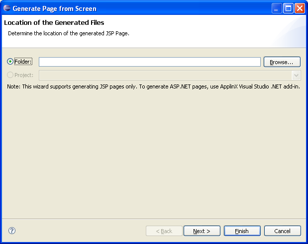
Determine the folder where the generated page will be placed.
Click . The Screen Contents screen is displayed.
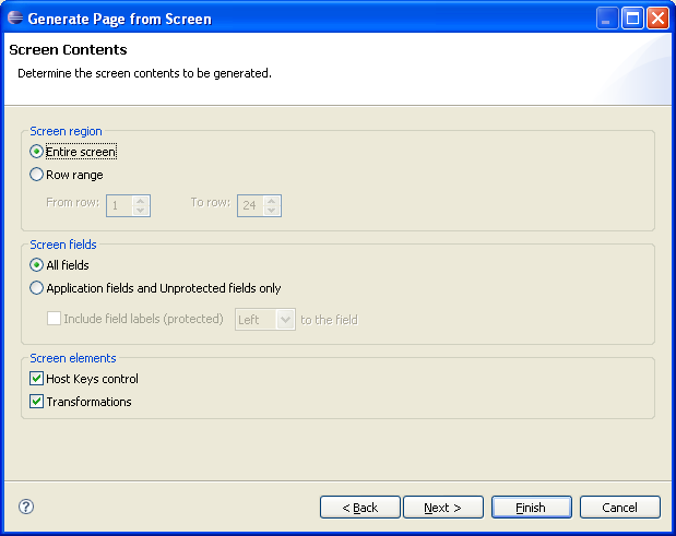
Determine the region in the screen that is to be generated: this can be the entire screen or a specific range of rows.
Determine the type of fields that are to be generated: all the fields or only application and unprotected fields.
Determine whether the host keys control and/or transformations are to be generated.
Click . The Code Snippets screen is displayed.
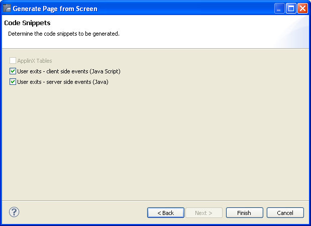
In the Code Snippets tab define the elements you would like to generate code behind for. The code class contains methods which can be used as a basis for further development. Click .
To generate an ASPX framework page:
Use the ApplinX Visual Studio .NET add in.