This document describes how to install the Natural IMS TM Interface (product code NII).
The following topics are covered:
For detailed information on using the Natural IMS TM Interface, refer to Natural under IMS TM in the Natural TP Monitor Interfaces documentation.
Notation vrs or vr: If used in the following document, the notation vrs or vr stands for the relevant version, release, system maintenance level numbers. For further information on product versions, see Version in the Glossary.
The following software must be installed and running before you install the Natural IMS TM Interface:
Base Natural under z/OS.
Natural global buffer pool if you are using the MPP environment (strongly recommended).
Natural roll server if the ROLLSRV
parameter of the Natural IMS TM Interface is set to YES.
Natural Authorized Services Manager with the SIP Server function, if the Non-Conversational MPP Interface, the monitoring or broadcasting function of the Natural IMS TM Interface is used.
Authorized Services Manager, if the Accounting to SMF function of the Natural IMS TM Interface is used.
Adabas IMS TM Interface (product code AII), version as specified under Natural and Other Software AG Products in the current Natural Release Notes for Mainframes.
For details, see the relevant sections in the Natural under IMS TM or Natural Operations documentation.
The installation tape contains the datasets listed in the table below. The sequence of the datasets is shown in the Report of Tape Creation which accompanies the installation tape.
| Dataset Name | Contents |
|---|---|
NIIvrs.LOAD |
Load modules of the Natural IMS TM Interface |
NIIvrs.SRCE |
Source programs and macros of the Natural IMS TM Interface |
If you are using SMA, refer to the System Maintenance Aid documentation (included in the current edition of the Natural documentation CD).
If you are not using SMA, follow the instructions below.
This section explains how to:
Copy dataset COPY.JOB from tape to disk.
Modify this dataset to conform to your local naming conventions.
The JCL in this dataset is then used to copy all datasets from tape to disk.
If the datasets for more than one product are delivered on the tape, the
dataset COPY.JOB contains the JCL to unload the datasets for all
delivered products from the tape to your disk.
After that, you will have to perform the individual install procedure for each component.
The dataset COPY.JOB (Label 2) contains the JCL to unload all
other existing datasets from tape to disk. To unload COPY.JOB, use
the following sample JCL:
//SAGTAPE JOB SAG,CLASS=1,MSGCLASS=X
//* ---------------------------------
//COPY EXEC PGM=IEBGENER
//SYSUT1 DD DSN=COPY.JOB,
// DISP=(OLD,PASS),
// UNIT=(CASS,,DEFER),
// VOL=(,RETAIN,SER=tape-volume),
// LABEL=(2,SL)
//SYSUT2 DD DSN=hilev.COPY.JOB,
// DISP=(NEW,CATLG,DELETE),
// UNIT=3390,VOL=SER=volume,
// SPACE=(TRK,(1,1),RLSE),
// DCB=*.SYSUT1
//SYSPRINT DD SYSOUT=*
//SYSIN DD DUMMY
//
where:
hilev is a valid high level
qualifier
tape-volume is the tape
volume name, for example: T12345
volume is the disk volume
name
Modify the COPY.JOB on your disk to conform to your local
naming conventions and set the disk space parameters before submitting this
job:
Set HILEV to a valid high level qualifier.
Set LOCATION to a storage location.
Set EXPDT to a valid expiration date.
Submit COPY.JOB to unload all other datasets from the tape to
your disk.
The sample jobs are contained in the dataset
NATvrs.JOBS and are prefixed with
NII.
The installation procedure comprises the following:
Perform the steps in the sequence indicated above.
The following steps are required to install the Natural IMS TM Interface in a BMP, an NTRD an MPP and/or a server environment:
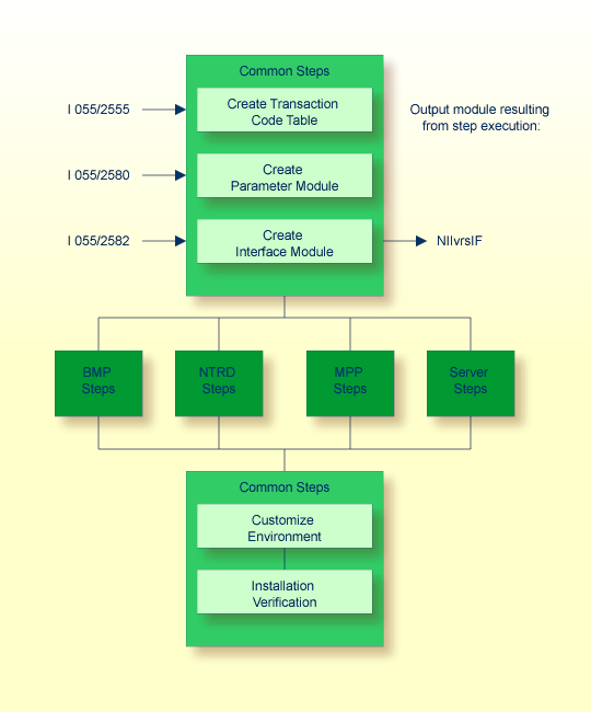
(Job I055, Steps 2555 and 2556)
Create the transaction code table by including a
NIMTRNTG macro for each transaction code used for Natural
transactions.
For further information on the parameters in the
NIMTRNTG macro, refer to
NIMTRNTG
Macro Parameters in the Natural TP Monitor
Interfaces documentation.
If you want to use Natural in non-message-driven BMP or a batch
environment, add a NIMTRNTG macro for the PSB used with an
arbitrary transaction code.
Assemble and link the transaction code table.
(Job I055, Steps 2580 and 2581)
Create the parameter module by including a NIMPARM
macro for each environment needed.
For information on the parameters for the NIMPARM
macro, refer to NIMPARM Macro
Parameters in the Natural TP Monitor
Interfaces documentation.
Assemble and link the parameter module.
(Job I055, Step 2582)
Link the interface module.
The same interface module can be used in a BMP, an NTRD, and MPP and/or a server environment.
The name of the interface module must be specified with the parameter
NIINAME in
the call to macro NIMDRIV
for all environment interfaces described in the following sections.
The following steps are required to install the Natural IMS TM Interface for the BMP environment:
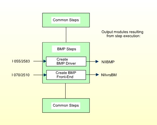
(Job I055, Steps 2583 and 2584)
Create the source NIIBMP which contains a call to macro
NIMDRIV with the parameter TYPE set to
BMP.
For further information on the macro NIMDRIV, refer to
the NIMDRIV Macro
Parameters in the Natural TP Monitor
Interfaces documentation.
Assemble and link the BMP interface.
For CMPRMTB you receive the warning
IEW0461. You can ignore this.
If the
NIMDRIV
parameter LE370
is not set to NO, you receive the warning IEW0461 for
modules starting with CEE. You can ignore this.
(Job I070, Step 2510)
The front-end consists of the BMP interface created in
Step 1 and your batch
Natural parameter module NATPARM.
Specify the name of the Natural batch parameter module with the
INCLUDE instruction in the parameter module (Job I060, Steps 0010,
0015).
Specify the name of the front-end module used for this link.
| Warning: This name must also be specified in your BMP region job as application program name (parameter MBR of the
IMSBATCH procedure invocation). |
Link the front-end for the BMP environment.
The following steps are required to install the Natural IMS TM Interface for the NTRD environment:
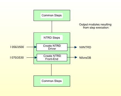
(Job I056, Steps 2500, 2501)
Create the source NIINTRD which contains a call to
macro NIMDRIV with the parameter TYPE set
to NTRD.
For further information on the macro NIMDRIV, refer to
the NIMDRIV Macro
Parameters in the Natural TP Monitor
Interfaces documentation.
Assemble and link the NTRD interface.
For CMPRMTB you receive the warning
IEW0461. You can ignore this.
If the
NIMDRIV
parameter LE370
is not set to NO, you receive the warning IEW0461 for
modules starting with CEE. You can ignore this.
(Job I070, Step 2530)
The front-end consists of the NTRD interface created in
Step 1 and of your batch
Natural parameter module NATPARM.
Specify the name of the Natural batch parameter module with the
INCLUDE instruction in the parameter module (Job I060, Steps 0010,
0015).
Specify the name of the front-end module used for this link.
| Warning: This name must also be specified in the APPLCNT
macro as application program name (parameter PSB), if
the NTRD front-end is invoked directly by transaction code and not by bootstrap
module. |
Link the front-end for the NTRD environment.
The following steps are required to install the Natural IMS TM Interface for the MPP environment:
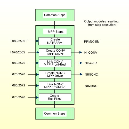
(Job I080, Steps 2500, 2510)
Set the values of the following parameters in the parameter module:
FNAT=(dbid,fnat)
FUSER=(dbid,fuser)
where dbid, fnat, and
fuser are the values you specified when
loading the system files in your base Natural installation. For further
information, see Installing Natural Under
z/OS.
To use a global Natural buffer pool, specify the macro
NTBPI
in the parameter module with the name of the global Natural buffer pool and set
the profile parameter SUBSID in the profile parameter
module.
If you want to use any other buffer pool, specify the macro
NTBPI in the parameter module for each required buffer
pool type.
It is strongly recommended that you use a global buffer pool for each buffer pool type.
If an Editor buffer pool is required, you must use a global Editor buffer pool.
Modify any other parameters in the parameter module whose default values do not meet your requirements. For further information on the parameters contained in the parameter module, refer to Using a Natural Parameter Module in the Natural Operations documentation.
Assemble and link the Natural parameter module for the dialog-oriented environments.
(Job I070, Steps 2565,2566)
Create the source NIICONV which contains a call to
macro NIMDRIV with the parameter TYPE set
to CONV.
For further information on the macro NIMDRIV, refer to
the NIMDRIV Macro
Parameters in the Natural TP Monitor
Interfaces documentation.
Assemble and link the Conversational MPP interface.
For CMPRMTB you receive the warning
IEW0461. You can ignore this.
If the
NIMDRIV
parameter LE370
is not set to NO, you receive the warning IEW0461 for
modules starting with CEE. You can ignore this.
(Job I080, Step 2570)
The front-end consists of the Conversational MPP interface created in
Step 2 and the online
Natural parameter module NATPARM created in
Step 1.
Specify the name of the online Natural parameter module in the
INCLUDE instruction for the parameter module.
Specify the name of the front-end module used for this link.
| Warning: This name must also be specified in the APPLCNT
macro as application program name (parameter
PSB). |
Link the front-end for the Conversational MPP environment.
(Job I070, Steps 2570, 2571)
Create the source NIINONC which contains a call to
macro NIMDRIV with the parameter TYPE set
to NONC.
For further information on the macro NIMDRIV, refer to
NIMDRIV
Macro Parameters in the Natural TP Monitor
Interfaces documentation.
Assemble and link the Non-Conversational MPP interface.
For CMPRMTB you receive the warning
IEW0461. You can ignore this.
If the
NIMDRIV
parameter LE370
is not set to NO, you receive the warning IEW0461 for
modules starting with CEE. You can ignore this.
(Job I080, Step 2572)
The front-end consists of the Non-Conversational MPP interface created
in Step 4 and the online
Natural parameter module NATPARM created in
Step 1.
Specify the name of the online Natural parameter module in the
INCLUDE instruction for the parameter module.
Specify the name of the front-end module used for this link.
| Warning: This name must also be specified in the APPLCNT
macro as application program name (parameter
PSB). |
Link the front-end for the Non-Conversational MPP environment.
(Job I070, Step 2590)
This step is only required if you do not use the Natural roll server.
If you do not want to use the Natural roll server, you have to allocate and format the roll files to be used by the Natural IMS TM Interface.
You can allocate up to 5 sequential datasets with a fixed-record format for use as roll files.
Allocate the roll files.
Format the roll files using the module NATRSRFI.
The roll file initialization program produces a WTO message indicating the number of concurrent users which can be serviced by the roll file. For information on the roll file facility, refer to Natural Roll Server Functionality in the Natural Operations documentation.
The following steps are required to install the Natural IMS TM Interface for the sever environment:
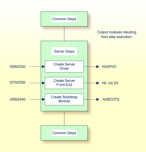
(Job I056, Steps 2530, 2531)
Create the source NIISRVD which contains a call to
macro NIMDRIV with the parameter TYPE set
to SRVD.
For further information on the macro NIMDRIV, refer to
NIMDRIV
Macro Parameters in the Natural TP Monitor
Interfaces documentation.
Assemble and link the server interface.
For CMPRMTB you receive the warning
IEW0461. You can ignore this.
If the
NIMDRIV
parameter LE370
is not set to NO, you receive the warning IEW0461 for
modules starting with CEE. You can ignore this.
(Job I070, Step 2550)
The front-end consists of the server interface created in
Step 1 and of your batch
Natural parameter module NATPARM.
Specify the name of the Natural batch parameter module with the
INCLUDE instruction in the parameter module (Job I060, Steps 0010,
0015).
Specify the name of the front-end module used for this link.
| Warning: This name must also be specified in the NIMBOOT
macro as driver name (parameter DRIVERN). |
Link the front-end for the server environment.
(Job I056, Steps 2540, 2541)
Create the source NIIBOOTS which contains a call to
macro NIMBOOT with the parameter SERVER set
to YES. For the DRIVERN parameter, specify
the name of the front-end module created in
Step 2.
Assemble and link the bootstrap module.
The following steps require system modifications to your IMS TM environment.
MPP Define Sample:
   APPLCTN PSB=NIIvrsFR,PGMTYPE=TP
      TRANSACT CODE=NATvrs,MODE=SNGL,SPA=512,
          MSGTYPE=(SNLGSEG,RESPONSE,9)
| Warning: The size of the SPA must be set to at least 157 bytes plus the NRASTART value. |
BMP Define Sample (Message-Driven or NAF-specific BMP):
   APPLCTN PSB=NIIvrsBM,PGMTYPE=BATCH
      TRANSACT CODE=NATvrsBM,MODE=SNGL,
          MSGTYPE=(SNLGSEG,RESPONSE,9)
This APPLCTN definition is required if you use the
CMGETMSG feature.
BMP Define Sample (without Message Queue Processing):
APPLCTN PSB=NIIvrsBM,PGMTYPE=BATCH
NTRD Define Sample:
   APPLCTN PSP=NIIvrsOB,PGMTYPE=TP
      TRANSACT CODE=NATvrsOB,MODE=SNGL,
          MSGTYPE=(MULTSEG,NONRESPONSE,10)
Example for MPP:
PSB for conversational Natural:
   PCB TYPE=TP,MODIFY=YES
   PCB TYPE=TP,MODIFY=YES
   PCB TYPE=TP,MODIFY=YES
   PCB TYPE=DB,DBNAME=dliddm,PROCOPT=A,KEYLEN=16 sample for NDL
   SENSEG NAME=EMPLOY,PROCOPT=A sample for NDL
   SENSEG NAME=VEHICL,PROCOPT=A,PARENT=EMPLOY sample for NDL

   PSBGEN PSBNAME=NIIvrsFR,LANG=ASSEM,MAXQ=3,IOASIZE=132
At least one modifiable TP-PCB must be defined for default use of
hardcopy, sending messages and transaction switching. To avoid a Natural
initialization error, the value of the WRKPCBS parameter
in the current environment table must be less than or equal to the number of
PCBs minus 1.
Example for BMP:
   PCB TYPE=TP,MODIFY=YES
   PCB TYPE=TP,MODIFY=YES
   PCB TYPE=DB,DBNAME=dliddm,PROCOPT=A,KEYLEN=16 sample for NDL
   SENSEG NAME=EMPLOY,PROCOPT=A sample for NDL
   SENSEG NAME=VEHICL,PROCOPT=A,PARENT=EMPLOY sample for NDL

   PSBGEN PSBNAME=NIIvrsBM,LANG=ASSEM,MAXQ=3,IOASIZE=132
At least one modifiable TP-PCB must be defined for default use of
hardcopy and sending messages. To avoid a Natural initialization error, the
value of the WRKPCBS parameter in the current
environment table must be less than or equal to the number of PCBs minus 1.
After creating the required APPLCTNs for the BMP and MPP
environments, you must generate the PSB, DBD and ACB.
After the ACB generation, the following commands activate the new definitions:
/MODIFY PREP ACBLIB
/MODIFY COMMIT
Use the sample members as guidelines when creating the specific regions for your installation.
BMPJOB
MPPJOB
Update the PRELOAD list using a PRELOAD
member DFSMPL xx with the following
module names:
the Natural nucleus name,
the interface module name,
the front-end name,
the Adabas link module name
Example for MPP:
NATvrsSH,NIIvrsIF,NIIvrsFR,ADALNI
Example for BMP:
NATvrsSH,NIIvrsIF,NIIvrsBM,ADALNK
If alias names are used for any members in the PRELOAD
list, these names should be added to the PRELOAD list as well.
Failure to do so leads to performance degradation.
Set the REGION parameter to at least
2MB.
Include the load libraries used by the Natural IMS TM Interface.
Include the DD statement for the roll file created in
Job I070, Step 2590:
//ROLLFn DD DSN=....DISP=SHR
where n is a value from 1 - 5.
Include the DD statement for NATRJE:
//NIIRJEDD DD SYSOUT=(X,INTRDR)
The multi-session feature is an optional feature of the Natural IMS TM Interface. For details, see the relevant section in the Natural TP Monitor Interfaces documentation.
The following steps have no corresponding example jobs in
NATvrs.JOBS.
Create the DBD using the member NIIMSDBD in
NIIvrs.SRCE.
Create the PSB for the initial load.
Add the DBD to all PSBs intended for use with the multi-session feature.
Define and load the database using the JCL INITDM in
NATvrs.JOBS.
| Parameter | Description |
|---|---|
MSACTV=YES |
Activates the session manager |
MSDBD=dbdname
|
Where dbdname is the
name used in MSDBD.
|
MSCRKEY |
The key to create a new session |
MSRSKEY |
The key to switch to a resumed session |
MSMAX=nn
|
Where nn is the number
of active sessions (max. 8)
|
For further information, see the sections Installing the Batch Message Processing BMP Environment and Installing the Dialog-Oriented MPP Environment.
Set the following parameter:
| Parameter | Description |
|---|---|
MSPCB |
Number of the multi-session PCB |
From an IMS TM session, start a BMP with the following IMS TM command:
/STA REG BMPJOB
Check the output. The output results from the Natural system command
TECH. Verify the output with your environment.
From an IMS TM session, issue the following IMS TM commands:
/STA REG MPPJOB
/STA TRAN NATvrs
/STA PROG NIIvrsFR
Type in transaction name
NATvrs.
Proceed with the steps described in the section Installation Verification for the TP Monitor Interface.