This section describes how to start and shut down the Data Mapping Tool and provides an overview of the Data Mapping Tool interface. It covers the following topics:
 To start the Data Mapping Tool in Windows environments, complete the
following steps:
To start the Data Mapping Tool in Windows environments, complete the
following steps:
From the Windows Start menu, select .
Select .
Select .
Select Event Replicator Target Adapter.
Select .
The Data Mapping Tool starts up and the Data Mapping Tool main window appears.
To start the Data Mapping Tool in UNIX environments, complete the
following steps:
Run the mappingtool.sh file in the installation directory.
The Data Mapping Tool starts up and its primary window appears.
To shut down the Data Mapping Tool:
Click the button on the Data Mapping Tool window.
The Data Mapping Tool shuts down.
This section describes the Data Mapping Tool window, menus, and buttons. It covers the following topics:
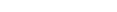
The Data Mapping Tool main window is divided into three columns.
The far left column, Input Data, lists available DDMs and Predict XML Definitions. Once you have identified a directory containing DDMs and Predict XML Definitions, the DDMs/Predict XML Definitions in that directory get listed in this column. For information on identifying the directory containing your DDMs/Predict XML Definitions, read Locating and Selecting Input Data.
The middle column, Target RDBMS, lists the target relational database tables to which you will map fields from your DDM/Predict XML Definition. To add and remove target relational databases from this list, read Adding a Target Database.
The right column, GFB Schema, displays the GFB schema that is created when you drag a DDM/Predict XML Definition onto an RDBMS. A GFB and field table (GFFT) can be generated from this schema.
The Data Mapping Tool main window includes five menus. The options available from these menus are described in this table.
| Menu | Menu Option | Description |
|---|---|---|
| File | Allows you to save the RDBMS target table and GFB schema listed on the screen. The next time you start up the Data Mapping Tool, this table and GFB schema will automatically appear. | |
| Allows you to shut down the Data Mapping Tool. | ||
| GFB1 | Allows you to redefine a field in the schema. For more information, read Redefining Schema Fields. | |
| Allows you to specify that a field selected in the schema is the primary key or is part of a composite key. For more information, read Specifying Keys. | ||
| Allows you to specify that a field selected in the schema is no longer the primary key or part of a composite key. For more information, read Specifying Keys. | ||
| Allows you to generate the GFB and field table, based on the selected GFB schema. For more information, read Generating a GFB and Field Table. | ||
| Options | Allows you to set the preferences for Data Mapping Tool processing. For more information, read Setting Preferences. | |
| Targets | Allows you to add and link to a target RDBMS. Once added, the RDBMS is listed in the middle column of the Data Mapping Tool main window. For more information, read Adding a Target Database. | |
| Targets | Allows you to add and link to an Analytics target. | |
| Help | Allows you to access the online help for the Data Mapping Tool | |
| Lists version information about this installation of the Data Mapping Tool. |
Notes:
The Data Mapping Tool main window includes the following buttons:
Note:
Some of these buttons only become useable if specific items
are selected in the Data Mapping Tool screen.
| Button | Description |
|---|---|
 |
Saves the current mappings shown in the Data Mapping Tool. Target definitions in the target list, GFB schemas, and source DDMs are saved. |
 |
Exits the Data Mapping Tool. |
 |
Allows you to redefine the selected GFB schema field. For more information, read Redefining Schema Fields. |
 |
Allows you to specify that a field selected in the schema is the primary key or is part of a composite key. For more information, read Specifying Keys. |
 |
Allows you to specify that a field selected in the schema is no longer the primary key or part of a composite key. For more information, read Specifying Keys. |
 |
Allows you to generate the GFB and field table, based on the selected GFB schema. For more information, read Generating a GFB and Field Table. |
 |
Exits the Data Mapping Tool. |
 |
Saves the current mappings shown in the Data Mapping Tool. Target definitions in the target list, GFB schemas, and source DDMs are saved. |
The button allows you to save the RDBMS target table and GFB schema listed on the screen. The next time you start up the Data Mapping Tool, this table and GFB schema will automatically appear.
The button allows you to shut down the Data Mapping Tool.
The Data Mapping Tool main window uses the following icons:
| Icon | Description |
|---|---|
 |
Identifies a DDM file in the leftmost pane. |
 |
Identifies a DDM in the leftmost pane, an RDBMS table in the center pane, and a GFB schema table in the rightmost pane. In addition, this icon precedes the and options on the right-click menu of an RDBMS or table in the center pane. |
 |
Identifies a simple field in the leftmost pane and an RDBMS column in the center pane. In addition, this icon precedes the and options on the right-click menu of a table in the center pane. |
 |
Identifies a multiple value (MU) field in the leftmost pane. |
 |
Identifies a flattened multiple value (MU) field in the leftmost pane. |
 |
Identifies a periodic group (PE) field in the leftmost pane. |
 |
Identifies a flattened periodic group (PE) field in the leftmost pane. |
 |
Identifies a redefined field in the leftmost pane. |
 |
Identifies a simple group field in the leftmost pane. |
 |
Identifies a subfield or superfield with occurrences in the leftmost pane. |
 |
Identifies a flattened subfield or superfield with occurrences in the leftmost pane. |
 |
Identifies a subfield or superfield with MU or PE occurrences in the leftmost pane. |
 |
Identifies a flattened subfield or superfield with MU or PE occurrences in the leftmost pane. |
 |
Identifies an RDBMS database in the center and rightmost panes. This icon also precedes the option on the menu. |
 |
Identifies a GFB schema in the
rightmost pane. In addition, this icon:
For more information, read Generating a GFB and Field Table. |
 |
Identifies a GFB schema field in the rightmost pane. |
|
Identifies an RDBMS or GFB schema
key field -- either the primary key or a field included in a composite key. In
addition, this icon:
For more information, read Specifying Keys. |
 |
Precedes the option on the right-click menu of a GFB schema composite key field in the rightmost pane. |
|
Precedes the option on the right-click menu of a GFB schema key
field in the rightmost pane. This icon also:
|
 |
Identifies a GFB schema foreign key in the rightmost pane. |
 |
Precedes the option on the right-click menu of a DDM field in the leftmost pane. For more information, read Flattening Fields for Replication. |
 |
Precedes the option on the right-click menu of a DDM field in the leftmost pane. For more information, read Flattening Fields for Replication. |
 |
Precedes the option on the right-click menu of a GFB schema or GFB schema field in the rightmost pane. |
|
Precedes the
option on the right-click menu of a GFB
schema field in the rightmost pane. This icon also:
For more information, read Redefining Schema Fields. |
 |
Identifies a child field of a redefined (split) field in the rightmost pane. |
|
Appears on a button that allows you to save the current mappings shown in the Data Mapping Tool. This icon also precedes the option on the menu. |
 |
Appears on a button that allows you to specify the directory in which data definition modules (DDMs) can be found. This icon also precedes the option on the menu. |
 |
Precedes the option on the right-click menu of a screen element. |
|
Appears on a button that allows you to exit the Data Mapping Tool. This icon also precedes the option on the menu. |
 |
Precedes the option on the right-click menu of a screen element. |
 |
Precedes the option on the menu. This option allows you to access the online help for the Data Mapping Tool. |
Preferences can be set for your use of the Data Mapping Tool. This section describes the preferences you can set.
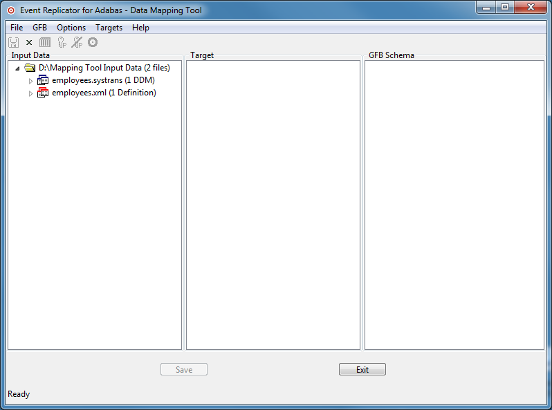
In this panel you can specify the default values for occurrences of PE/MU fields and binary fields.
When you create a GFB schema, you can specify the number of multiple-value (MU) and periodic group (PE) field occurrences for each MU or PE field in the DDM. However, you can also set a default number of occurrences to be applied to the MU and PE fields prior to creating the GFB schema. This section describes how to set this default. You can override this default if you decide to flatten the MU and PE fields in the resulting RDBMS table or when you create the GFB schema using the Data Mapping Tool.
Using the preferences described in this section, you can control the default number of MU and PE field occurrences for each MU or PE field in the DDM.
To manage your MU and PE field preferences, complete the
following steps:
Access the preferences area of the Data Mapping Tool by selecting "Preferences..." on the Options menu.
The Preferences dialog appears.
Select "PE/MU Occurrences" on the left side of the dialog to display the MU and PE field preferences.
The right side of the dialog displays the MU and PE field preferences under the heading Defaults.
In the Default Occurrences field, specify the default number of repeating elements for each MU or PE field that can be expected in the DDM.
When you have specified a default number of MU and PE field occurrences, select (check) the Rescan DDM Directory option. When you click OK or Apply in the next step, this option will cause the Data Mapping Tool to rescan the DDM directory you have specified, adjusting the MU and PE fields in the listed DDMs to reflect this occurrence setting.
When all preferences have been set, click one of the following buttons:
Click "Apply" to apply the preference settings and keep the Preferences dialog open.
Click "Cancel" to cancel the preference settings and close the Preferences dialog.
Click "OK" to apply the preference settings and close the Preferences dialog.
Click "Restore Defaults" to restore the factory defaults for the preference settings and keep the Preferences dialog open.
For binary fields with a length less or equal 8 bytes the character set can be specify by the user. With this option you can set the default value.
The leftmost Input Data column of the Data Mapping Tool main window may or may not display any DDMs/Predict XML Definition, depending on whether the file extensions and locations of your DDM/XML files match the DDM/XML file extensions and locations specified in the Data Mapping Tool preferences.
Using the preferences described in this section, you can control the default location and file extensions of the data definition module (DDM)/Predict XML definition files used in the Data Mapping Tool main window. When you start up the Data Mapping Tool, the DDMs/XML that match these criteria are automatically listed in the leftmost pane of the Data Mapping Tool main window.
To manage your DDM/XML file preferences, complete the
following steps:
Access the preferences area of the Data Mapping Tool by selecting "Preferences... "on the Options menu.
The Preferences dialog appears.
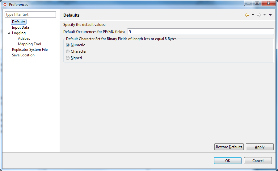
Select "Input Data" on the left side of the dialog to display the Data Mapping Tool DDM/XML file preferences.
The right side of the dialog displays the DDM/XML file preferences under the heading Input Data.
Use the "Input Data Directory" field to specify the default location of your DDMs/XML. Use the Browse button to locate a directory location for the DDMs/XML.
Use the DDM/XML File Extensions fields to list all of the file extensions of your available DDMs/XML files. Separate the file extension specifications with a semicolon (;).
When all preferences have been set, click one of the following buttons:
Click "Apply" to apply the preference settings and keep the Preferences dialog open.
Click "Cancel" to cancel the preference settings and close the Preferences dialog.
Click "OK" to apply the preference settings and close the Preferences dialog.
Click "Restore Defaults" to restore the factory defaults for the preference settings and keep the Preferences dialog open.
You can request that a log be kept of your attempts to upload
a generated GFB/GFFT to a mainframe Replicator system file. Upload log files
have file names in the format jnnnnnnn.log, where
nnnnnnn is a sequential number. If you request that such logs
be kept, a new log is created for each upload attempt.
The log files can be reviewed using a text editor. You can control whether these log files should be created and the location in which the logs should be stored.
To manage your upload logging preferences, complete the
following steps:
Access the preferences area of the Data Mapping Tool by selecting "Preferences..." on the Options menu.
The Preferences dialog appears.
Expand the "+" next to Logging.
Select "Adabas Logging" on the left side of the dialog to display the upload log preferences.
The right side of the dialog displays the upload log preferences under the heading Adabas.
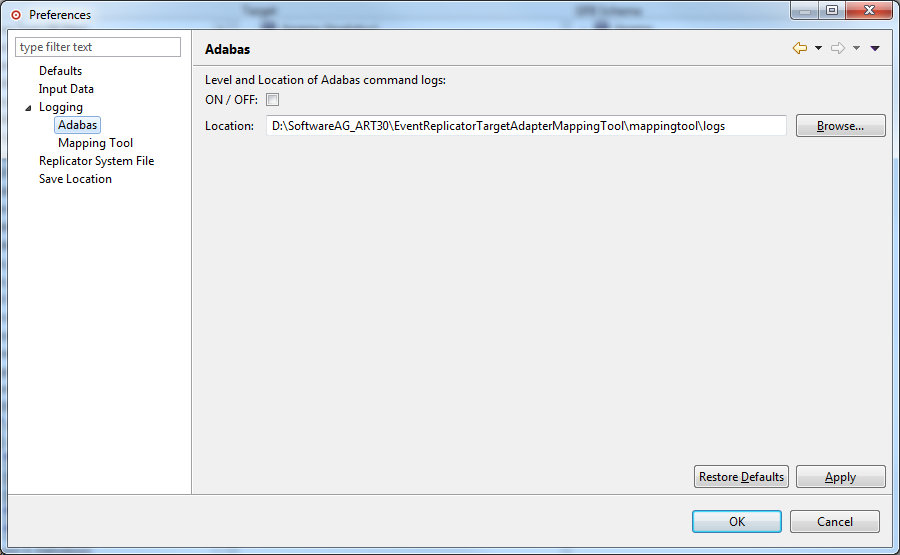
Specify the upload log preferences you want to use for the Data Mapping Tool, as described in the following table:
| Preference | Description |
|---|---|
| ON/OFF | Check this check box if you want upload logs to be created. If you do not want them created, leave this check box unchecked. |
| Location | Specify the location where
the upload logs should be stored. The default location
(<path>\MappingTool\logs) is shown the first time you access
these preferences. Use the Browse button to locate a directory location for the
log files.
|
When all preferences have been set, click one of the following buttons:
Click "Apply" to apply the preference settings and keep the Preferences dialog open.
Click "Cancel" to cancel the preference settings and close the Preferences dialog.
Click "OK" to apply the preference settings and close the Preferences dialog.
Click "Restore Defaults" to restore the factory defaults for the preference settings and keep the Preferences dialog open.
When the Data Mapping Tool is installed, all Data Mapping Tool messages are automatically written to a Data Mapping Tool log file. The log file contains all current log messages, including statistics about the Data Mapping Tool session processing. If you have a problem, please keep this log file.
Data Mapping Tool log files have file names in the format
MT-Log.txt.[nn], where nn is the sequential number of the log file
(newest log files have the lowest or no number). If you request that such logs
be kept, a new log is created each time you start up the mapping tool.
The log files can be reviewed using a text editor.
You can control the level (severity) of log messages written to these logs as well as the location in which the logs are stored.
To manage your Data Mapping Tool logging preferences,
complete the following steps:
Access the preferences area of the Data Mapping Tool by selecting "Preferences..." on the Options menu.
The Preferences dialog appears.
Expand the "+" next to Logging.
Select "Mapping Tool Logging" on the left side of the dialog to display the Data Mapping Tool log preferences.
The right side of the dialog displays the Data Mapping Tool log preferences under the heading "Mapping Tool" .
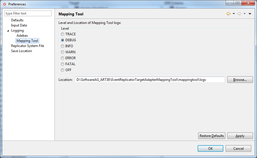
Use the "Level" field to set the log level of messages written to the Data Mapping Tool log files. Seven log levels are available (listed in order of settings that result in the most logging to those resulting in the least logging):
| Log Level | Description |
|---|---|
| TRACE | All messages are logged or
displayed.
Note: |
| DEBUG | Only debugging,
informational, warning, error, and fatal messages are logged or displayed.
Note: |
| INFO | Only informational, warning, error, and fatal messages are logged or displayed. |
| WARN | Only warning, error, and fatal messages are logged or displayed. |
| ERROR | Only error and fatal messages are logged or displayed. |
| FATAL | Only fatal messages are logged or displayed. |
| OFF | No logging occurs. |
Click on the level you want to use.
Use the Location field to specify the location where the
Data Mapping Tool logs should be stored. The default location
(<path>\MappingTool\logs) is shown the first time you access
these preferences. Use the Browse button to locate a directory location for the
log files.
When all preferences have been set, click one of the following buttons:
Click "Apply" to apply the preference settings and keep the Preferences dialog open.
Click "Cancel" to cancel the preference settings and close the Preferences dialog.
Click "OK" to apply the preference settings and close the Preferences dialog.
Click "Restore Defaults" to restore the factory defaults for the preference settings and keep the Preferences dialog open.
The GFBs and field tables (GFFTs) that you generate using the Data Mapping Tool can be uploaded to a Replicator system file or saved to at text file that can be used in an Event Replicator RPLOD utility run.
Using the preferences described in this section, you can control where the text files are saved and you can specify the information necessary for the Data Mapping Tool to access and upload the GFB/GFFT to the correct Replicator system file.
To manage your GFB/GFFT upload preferences, complete the
following steps:
Access the preferences area of the Data Mapping Tool by selecting "Preferences..." on the Options menu.
The Preferences dialog appears.
Select "Replicator System File" on the left side of the dialog to display the Data Mapping Tool GFB/GFFT upload preferences.
The right side of the dialog displays the GFB/GFFT preferences under the heading Replication System File.
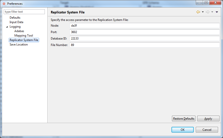
Use the remaining fields on this panel to identify the location of the Replicator system file that should be used if you choose to upload the generated GFB/GFFT. These fields are described in the following table:
| Field | Description |
|---|---|
| Node | Specify the network node where the Replicator system file can be found. This is the TCP/IP host or IP address where the Event Replicator Server nucleus resides. |
| Port | Specify the port number where the Replicator system file can be found. This is the TCP/IP port number used by the Entire Net-Work TCP/IP Option on the mainframe. |
| Database ID | Specify the database ID of the database containing the Replicator system file. This is the database ID of the Replicator nucleus. |
| File Number | Specify the file number of the Replicator system file. |
When all preferences have been set, click one of the following buttons:
Click "Apply" to apply the preference settings and keep the Preferences dialog open.
Click "Cancel" to cancel the preference settings and close the Preferences dialog.
Click "OK" to apply the preference settings and close the Preferences dialog.
Click "Restore Defaults" to restore the factory defaults for the preference settings and keep the Preferences dialog open.
Before you can use the Data Mapping Tool to generate a GFB and field table, you must create a schema from which the GFB and field table will be generated. For complete information on creating and maintaining a schema, read Creating and Maintaining the GFB Schema. During the creation of the schema you have options to save it.
The GFBs and field tables (GFFTs) that you generate using the Data Mapping Tool can be uploaded to a Replicator system file or saved to at text file that can be used in an Event Replicator RPLOD utility run.
Using the preferences described in this section, you can control where your schema and GFB/GFFT files are saved.
To manage your mapping file preferences, complete the
following steps
Access the preferences area of the Data Mapping Tool by selecting "Preferences..." on the Options menu.
The Preferences dialog appears.
Select "Save Location" on the left side of the dialog to display the mapping (schema) file preferences.
The right side of the dialog displays the mapping (schema) file preferences under the heading Save Location.
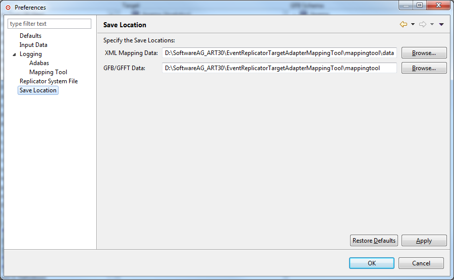
Use the "XML Mapping Data" field to specify the directory path in which schema files should be stored.
Use the "Save Location" field to specify the location where the generated GFB/GFFT text files for the RPLOD utility should be stored.
Use the "Browse" button to locate the directory if needed.
When all preferences have been set, click one of the following buttons:
Click "Apply" to apply the preference settings and keep the Preferences dialog open.
Click "Cancel" to cancel the preference settings and close the Preferences dialog.
Click "OK" to apply the preference settings and close the Preferences dialog.
Click "Restore Defaults" to restore the factory defaults for the preference settings and keep the Preferences dialog open.
A source data definition module (DDM) or Predict XML Definition is required for Data Mapping Tool processing. A DDM can be generated and saved using Software AG's Natural or Predict products. A Predict XML Definition can be created using a Natural User exit.
The leftmost Input Data column of the Data Mapping Tool main window may or may not display any DDMs, depending on the file extensions and locations of your DDM files. If all of your DDMs are shown, you are finished. If only some or none of your DDMs appear, you need to verify that the Data Mapping Tool has an accurate list of your DDM file extensions as well as the correct location of the DDMs. For information on specifying the DDM file extensions and file locations, read Managing Input Data.
Even if the Data Mapping Tool main window does not show any DDMs, you can locate and select one from the Data Mapping Tool. This section describes how to do this.
To locate and select a DDM/XML file to use, complete the
following steps:
Be sure you have generated and saved a DDM/XML input file using Software AG's Natural or Predict products.
Start up the Data Mapping Tool and examine the list of available input files in the leftmost pane of the Data Mapping Tool main window (Input Data).
If your DDM/XML is listed in the Input Data pane of the Data Mapping Tool main window, select it by clicking on it to highlight it.
If your DDM/XML input file is not listed in this column, you may need to set your preferences to the location where you placed the saved definition, follow the procedures above under Setting Preferences.
A Predict XML definition (XML) of your Adabas database must be generated from Software AG's Predict product using the user exit USR3005N. For more information, read your Predict documentation. A sample XML of the Adabas Employees demo file is included in the Data Mapping Tool installation.
Here is an example program. Make sure that SYSEXT is set as steplib …
DEFINE DATA LOCAL
  1 FILENAME(A32) INIT <'EMPL*'>
  1 REQUEST-RESULT(A) DYNAMIC
  1 #WORK (A) DYNAMIC
  1 #OFF (I4)
END-DEFINE
DEFINE WORK FILE 1 TYPE 'UNFORMATTED'
PRINT 'With this program you can unload Predict File definitions'
-     ' to be used by the Mapping Tool.'
/
INPUT (AD=MILT) 'Please enter the Filename: ' FILENAME
COMPRESS
'<Predict>'
  '<Request>'
    '<Select>'
**
** Search Adabas-File having a name which starts with entered file name
**
      '<Search>'
        '<Object-type value=''FILE-A'' value2=''FILE-U''/>'
        '<Attribute name=''ID'' value=''' FILENAME ''' />'
      '</Search>'
**
** Return the following attributes
**
      '<Return>'
        '<Field name=''ID''/>'
        '<Field name=''ELEMENT-LIST-TAB''/>'
      '</Return>'
    '</Select>'
  '</Request>'
'</Predict>'
*
TO REQUEST-RESULT LEAVING NO
*
*
CALLNAT 'USR3005N' REQUEST-RESULT
*
REPEAT
  EXAMINE REQUEST-RESULT FOR '><' GIVING POSITION #OFF
  IF #OFF NE 0
    MOVE SUBSTR(REQUEST-RESULT,1,#OFF) TO #WORK
    #OFF := #OFF + 1
    MOVE SUBSTR(REQUEST-RESULT, #OFF ) TO REQUEST-RESULT
  ELSE
    #WORK := REQUEST-RESULT
  END-IF
  WRITE WORK 1 VARIABLE #WORK
  IF #OFF = 0
    ESCAPE BOTTOM
  END-IF
END-REPEAT

PRINT 'Data written to workfile 1'
STOP
*
END
By default, when MU and PE fields and subfields and superfields are included in the replicated data, additional tables are created, as described in MU and PE Field Support. However, you can request that individual MU fields, PE fields, subfields, and superfields be flattened in the replicated data instead. This process of flattening fields will replicate them as columns in the main table, rather than as separate subtables.
If you want to flatten a field in the resulting RDBMS table, you must trigger it in the DDM specification for the field. If you do not explicitly trigger a field to be flattened in DDM, it will not be flattened in the resulting RDBMS tables.
Note:
You can flatten an MU field within a PE group without
flattening the entire PE group.
This section covers the following topics:
To trigger field flattening for a field, you must edit the field in your DDM. This section describes this process.
To trigger field flattening for a field:
Expand the DDM/XML in the Input Data column of the Data Mapping Tool main window.
DDM/XML files contain one or more DDMs/XML files. DDM
files are prefixed with the icon ;
XML are prefixed with the icon  .
.
Scroll through the fields in the DDM and locate the MU
field, PE field, subfield, or superfield for which you want to trigger
flattening. MU fields are identified with the
icon, PE fields are identified with
the  icon, and subfields and
superfields are identified with the
icon.
icon, and subfields and
superfields are identified with the
icon.
Right-click on the field and select from the drop-down menu.
A Flatten dialog appears. For example, the following is a Flatten dialog for a PE field.
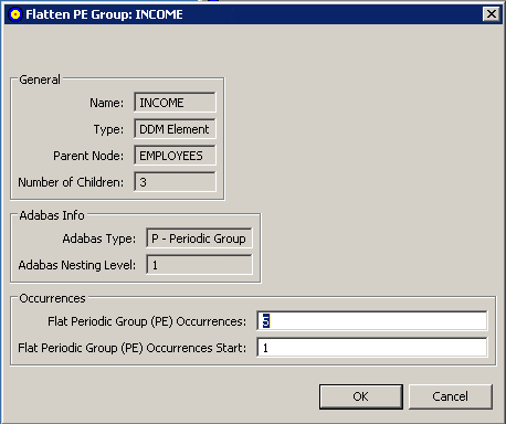
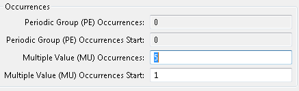
The Occurrences area of the dialog contains two editable fields:
Flat Multiple Value (MU) Occurrences or Flat Periodic Group (PE) Occurrences
Flat Multiple Value (MU) Occurrences Start or Flat Periodic Group (PE) Occurrences Start
Optionally, in the Flat Multiple Value (MU) Occurrences or Flat Periodic Group (PE) Occurrences field, specify the number of repeating elements for the field. Valid values must be positive integers.
Note:
A default number is supplied for this field. To specify
what this default value should be, read Specifying Defaults.
Optionally, in the Flat Multiple Value (MU) Occurrences Start or Flat Periodic Group (PE) Occurrences Start field, specify the starting occurrence number. For example, if you want to start with occurrence 15 rather than occurrence 1 (the default), you would specify "15" here.
Click when finished.
The fields will be marked for flattening when the GFB schema is created. In addition, the DDM/XML will expand with additional occurrences of the flattened fields as specified. You can use this updated DDM/XML then when creating and maintaining the GFB schema.
If, after you have specified that flattening should occur for a field, you decide not to flatten it, you need to remove the flattening trigger defined for the field in the DDM. This section describes this process.
To remove the field flattening trigger for a field:
Expand the DDM/XML in the Input Data column of the Data Mapping Tool main window.
Scroll through the fields in the DDM/XML and locate the MU
field, PE field, subfield, or superfield for which you want to trigger
flattening. Flattened MU fields are identified with the
icon, flattened PE fields are
identified with the icon, and
flattened subfields and superfields are identified with the
icon.
Right-click on the field and select from the drop-down menu.
The DDM/XML will remove the additional fields created by the flattening trigger. You can use this updated DDM/XML then when creating and maintaining the GFB schema.
This section describes how to manage the list of target RDBMS databases in the Data Mapping Tool. It covers the following topics:
To add a target relational database (RDBMS):
Select the menu option from the menu .
The Add RDBMS Target window appears.
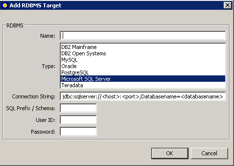
Fill in the fields on the Add RDBMS Target window as described in the following table:
| Field Name | Description | Required? |
|---|---|---|
| Name | Specify the name of the target database. | Yes |
| Type | Scroll through the list of RDBMS types and select any of the listed database types. | Yes |
| Connection String | Edit the connection string that appears, based on the type of database you have selected. . | Yes |
| SQL Prefix / Schema | Specify the SQL prefix or schema for the target database, if necessary. This specification is case-sensitive and is required for Oracle and DB2 databases. | No |
| User ID | Specify a user ID authorized to access and update the RDBMS. | Yes |
| Password | Specify the password of the user ID with authorization for the RDBMS. | Yes |
When all fields have been supplied as required, click the button to save the connection to the RDBMS.
The Data Mapping Tool main window reappears and the RDBMS is listed in the Target RDBMS column.
To remove a target database from the list in the
Target RDBMS column of the Data Mapping Tool main
window:
Right-click on the RDBMS in the Target RDBMS list that you want to remove.
Select the menu option from drop-down menu.
The target database is removed from the list. The RDBMS itself is not removed; it is removed only from the list in the Target RDBMS column. To remove the tables from the RDBMS, you must do so using the management tools provided with the RDBMS.
You can optionally show the RDBMS tables and refresh the list of tables, as needed.
To show the tables in an RDBMS listed in the
Target RDBMS column of the Data Mapping Tool main
window:
Right-click on the RDBMS in the Target RDBMS list whose tables you want to show.
Select the menu option from drop-down menu.
The list of tables in the RDBMS appears.
To refresh the table list for an RDBMS listed in the
Target RDBMS column of the Data Mapping Tool main
window:
Right-click on the RDBMS in the Target RDBMS list whose tables you want to refresh.
Select the menu option from drop-down menu.
The list of tables for the RDBMS is refreshed.
You can optionally show the columns in an RDBMS table and refresh the list of columns in a table, as needed.
To show the columns in an RDBMS table listed in the
Target RDBMS column of the Data Mapping Tool main
window:
Expand the RDBMS in the Target RDBMS column to see the tables included in it. If you cannot expand the RDBMS, verify that you have requested that the tables be shown for that RDBMS. Read Showing and Refreshing RDBMS Tables for more information.
Right-click on the RDBMS table in the Target RDBMS list whose columns you want to show.
Select the menu option from drop-down menu.
The list of columns in the RDBMS table appears.
To refresh the column list for an RDBMS table listed in the
Target RDBMS column of the Data Mapping Tool main
window:
Right-click on the RDBMS table in the Target RDBMS list whose columns you want to refresh.
Select the menu option from drop-down menu.
The list of columns for the RDBMS table is refreshed.
You can maintain the connection properties for any RDBMS listed in the Target RDBMS column of the Data Mapping Tool main window.
To review connection properties for an RDBMS:
Right-click on the RDBMS in the Target RDBMS list whose properties you want to review and maintain.
Select the menu option from drop-down menu.
The properties are displayed in a Properties dialog.
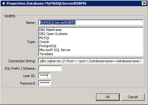
Alter the fields on the Properties, if necessary, as described in Adding a Target Database.
You cannot alter RDBMS table and column properties using the Data Mapping Tool. However, you can review them.
To review RDBMS table properties:
Right-click on the table name in the Target RDBMS pane of the Data Mapping Tool main window.
A drop-down menu appears.
Select from the drop-down menu.
The Properties:Table:tblname dialog appears.
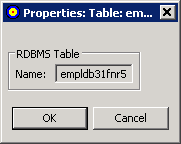
This dialog identifies the name of the RDBMS table.
To review RDBMS column properties:
Right-click on the column name in the Target RDBMS pane of the Data Mapping Tool main window.
A drop-down menu appears.
Select from the drop-down menu.
The Properties:Column:colname dialog appears.
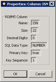
This dialog identifies:
The name of the RDBMS column.
The size of the RDBMS column.
The number of decimal digits of the RDBMS column.
The data type of the RDBMS column.
Whether the column is a primary key column. Valid values are "true" (it column is a primary key column) or "false" (the column is not a primary key column).
The sequence number of the column if it is part of a composite key. If the column is a primary key and no composite key is used, the Key Sequence will always be "1". If the column is not a primary key or part of a composite key, the Key Sequence will always be "0".
This section describes the creation and maintenance of GFB schema using the Data Mapping Tool. It covers the following topics:
Note:
If you want to use UTF-8 character encoding, you must verify
that your GFB field lengths are increased as required to accommodate the
character set referenced by the code page you select and the data requested in
the GFB. You can increase these field lengths manually by editing the Predict
file or data definition module (DDM) used when the GFB is generated.
You can create a GFB schema that maps all the fields in the DDM to tables in your RDBMS. One table is created with the same name as the DDM and additional tables are created for each MU or PE field within the DDM.
Once a GFB schema is created, you can use it to generate a global format buffer (GFB) and associated field table (GFFT) for use by the Event Replicator for Adabas and the Event Replicator Target Adapter. For more information, read Generating a GFB and Field Table.
To create the GFB schema from an entire DDM, complete the
following steps:
Drag and drop a DDM from the SYSTRANS DDMs (leftmost) pane onto a target RDBMS in the Target RDBMS (middle) pane. For complete information on listing DDMs in the SYSTRANS DDMs column and target relational databases in the Target RDBMS pane, read Locating and Selecting Input Data and Maintaining the Target Relational Database List.
Note:
If you want to use UTF-8 character encoding, you must
verify that your field lengths are increased as required to accommodate UTF-8
character encoding
A Define GFB Schema Name dialog appears.
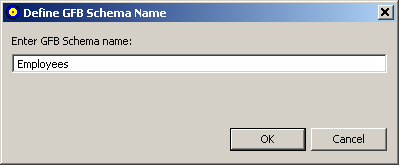
Specify the name you want to use for the RDBMS table on the Define GFB Schema Name dialog. The name can be up to 32 characters long. The name you specify is used for the RDBMS table and its subtables.
Note:
This is not the same as the name of the global format
buffer (GFB) definition used by the Event Replicator for Adabas.
In addition, once you have selected a name here, you can always rename it in the GFB Schema area of the Data Mapping Tool. For more information on renaming tables, the GFB Schema, read Renaming Schema Tables.
Click .
The Set MU/PE Occurrences dialog appears, allowing you to specify the number of occurrences for MU and PE fields for which no flattening has been triggered. The following is an example of this dialog:
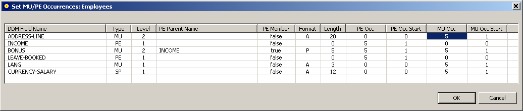
Optionally, adjust the MU or PE occurrence counts (MU Occ and PE Occ fields) and the MU or PE starting occurrence number (MU Occ Start and PE Occ Start fields) for the unflattened MU and PE fields listed in this dialog. Valid values must be positive integers.
Click when finished.
When all MU and PE fields have been accounted for, the GFB schema is created in the GFB Schema (rightmost) pane of the Data Mapping Tool main window.
The GFB schema consists of one or more tables. One table is created for the DDM; an additional table is created for each unflattened MU field, PE field, subfield, or superfield in the DDM.
You can create a GFB schema that maps individual fields in a DDM/XML to existing tables in your RDBMS. You can also create a GFB schema that maps all the fields in a DDM/XML to previously undefined tables in your RDBMS. For more information, read Creating the Schema from an Entire DDM/XML. Once a GFB schema is created, you can use it to generate a global format buffer (GFB) and associated field table for use by the Event Replicator for Adabas and the Event Replicator Target Adapter. For more information, read Generating a GFB and Field Table.
Note:
By default, if the table you are mapping to was not
originally created by the Event Replicator Target Adapter, it may not contain the field ISN. If this is
the case, replication to this target will likely fail with an error indicating
that the RDBMS does not contain an ISN column. Even if the ISN field is not
defined as a primary key, its value in each Adabas record is always replicated
to the target base (parent) table. To resolve this problem, we recommend that
you alter the table in your target RDBMS, adding a column named
"ISN" and defined as type integer. Alternatively,
you could set the Event Replicator Target Adapter Adabas-RDBMS Synchronization Level
field to "apply" in the target database option
definition for replication to your RDBMS. For more information about target
database option definitions in Event Replicator Target Adapter, read Specifying Target Database
Processing Option Definitions.
To create the GFB schema from individual fields in the
DDM/XML, complete the following steps:
Be sure that you have expanded the tables and table columns in the Target RDBMS pane of the Data Mapping Tool main window.
Drag and drop a single field from the DDM/XML in the Input Data (leftmost) pane onto an existing field (table column) name in a table in the target RDBMS listed in the Target RDBMS (middle) pane.
The following general rules must be followed:
For MU (multiple occurrence), PE (periodic group), SB (subfield), or SP(superfield) fields, the target table name must conform to the primary/foreign key naming relationships used by the Event Replicator Target Adapter.
The length of the field being mapped must not exceed the length of the field (column) in the RDBMS table.
Consideration should be given to matching data types of the fields in the DDM/XML and the fields in the target table. Do not attempt to map fields of different data types.
If you want to use UTF-8 character encoding, you must verify that your field lengths are increased as required to accommodate UTF-8 character encoding.
Duplicate mappings in the same target table are not allowed. You cannot map the same field to the same target RDBMS table and column combination.
If the ISN is not the primary key of your existing RDBMS table, you must change the primary key assignment. Likewise, if your RDBMS table uses multiple primary keys, you must set each composite key field and then specify the composite key order. For more information on maintaining primary and composite keys in your GFB schema, read Specifying Keys.
Note:
In addition, if ISN is not the primary key, you
must also manually add a dummy ISN column into the target table with integer as
its data type. This will ensure that replication occurs successfully.
For complete information on listing DDMs/XML in the Input Data pane and target relational databases in the Target Table pane, read Locating and Selecting Input Data and Linking to a Target Database.
The GFB schema is partially created in the rightmost (GFB Schema) pane of the Data Mapping Tool main window.
Repeat step 1 until all fields are mapped.
The GFB schema is updated in the GFB Schema (rightmost) pane of the Data Mapping Tool main window.
Optionally, rename the GFB schema in the GFB Schema pane. By default, schemas created from individual fields in the DDM have the same name as the name of the RDBMS table to which they are mapped. For complete information on renaming a GFB schema, read Renaming Schemas.
Click when finished.
The GFB schema has been created in the GFB Schema (rightmost) pane of the Data Mapping Tool main window. You can now use the Data Mapping Tool to generate a GFB and field table from the GFB schema.
Once a GFB schema is created, you can rename it if necessary.
To rename a GFB schema once it is created:
Right-click on the name of the schema you want to rename in the GFB Schema column of the main Data Mapping Tool window.
GFB schema names (which will result in the main table name
of your RDBMS table) are shown in the list prefixed by the icon
.
A drop-down menu appears.
Select from the drop-down menu.
A Rename GFB Schema dialog appears.
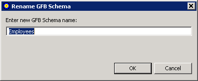
Specify a new name for the GFB schema in the dialog box and click
The GFB schema is renamed.
Once a GFB schema is created, you can rename any of the schema subtables produced for unflattened PE groups or MU fields.
To rename a GFB schema subtable in a GFB schema:
Right-click on the name of the schema subtable you want to rename in the GFB Schema column of the main Data Mapping Tool window.
GFB schema subtable names (which will result in the name
of a subtable in your RDBMS table) are shown in the list prefixed by the icon
.
A drop-down menu appears.
Select from the drop-down menu.
A Rename GFB Schema Table dialog appears.
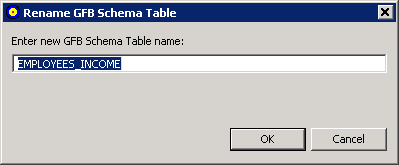
Specify a new name for the GFB schema subtable in the dialog box and click
The GFB schema subtable is renamed.
Once a GFB schema is created, you can rename any of the schema fields in the table if necessary.
To rename a GFB schema field in an GFB schema:
Right-click on the name of the schema field you want to rename in the GFB Schema column of the main Data Mapping Tool window.
GFB schema field names (which will result in the name of a
column in your RDBMS table) are shown in the list prefixed by the icon
.
A drop-down menu appears.
Select from the drop-down menu.
A Rename RDBMS Column Mapping dialog appears.
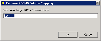
Specify a new name for the GFB schema field (RDBMS table column) in the dialog box and click
The field is renamed.
You can review the proprieties of a GFB schema field.
To review a GFB schema field's properties:
Right-click on the name of the schema field whose properties you want to review in the GFB Schema column of the main Data Mapping Tool window.
GFB schema field names are shown in the list prefixed by
the icon .
A drop-down menu appears.
Select from the drop-down menu.
The Properties: GFB Schema Field: fieldname dialog appears, listing the GFB schema field properties.
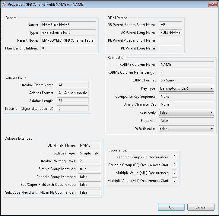
Most of the fields in this dialog are read-only.
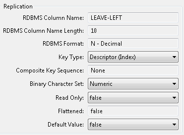
The key type, and read-only and default value settings of any field can be modified. In addition, for some fields you can alter the binary character set specification.
If the field is an MU field, a PE field, a subfield, or a superfield you can modify the settings in the Occurrences section of this dialog. The following example shows the Occurrences section of a field properties dialog for an MU field:
Optionally, alter the following properties:
Click on the arrow associated with the Key Type property to alter the key type. Valid specifications are "No Key", "Descriptor (Index)", and "UQ Descriptor (Unique Index)".
Click on the arrow associated with the Read Only property to alter the read-only status of the field. Valid specifications are "true" and "false".
Click on the arrow associated with the Default Value property to alter the property. Default Value options are true and false. Setting this option to "true" will cause Event Replicator to send zeroes in place of null for numeric fields with no value in Adabas, and a space in place of null for empty string fields. The use of this option requires Event Replicator for Adabas Version 3.6 SP1 and required zaps. Please consult the Event Replicator for Adabas documentation and consult with your support representative for the latest zap requirements.
If allowed for the field, click on the arrow associated with the Binary Character Set property to alter the binary character set for the field. Valid specifications are "Numeric", "Character", and "Signed".
If the field is an MU field, a PE field, a subfield, or a superfield, optionally modify the occurrence count or starting occurrence number in the Occurrences section of the dialog.
Click when you are done reviewing the properties.
Once you have created a GFB schema, you can redefine a schema field. This is especially useful if you want to split a field into multiple smaller fields (column) in the resulting RDBMS table. In a Data Mapping Tool schema, you can redefine a field into multiple fields unless it is:
a key field (primary or composite key field)
a descriptor field (superdescriptor, subdescriptor, hyperdescriptor, phonetic, or collation descriptor)
Note:
Installations wishing to redefine schema fields must have
Event Replicator for Adabas 3.2.1 or later installed.
Multiple value fields (MU fields) and periodic groups (PE fields) are supported.
In addition, you can redefine fields into combinations of the following data types: alphanumeric, binary, date, floating point, integer, logical, numeric, packed decimal, and time.
Finally, a field that is redefined cannot be expanded beyond its original field length unless it is first expanded in the original record and associated DDM. Once a GFB schema is created, you cannot increase the overall size of a field; so the sum of the sizes of the child fields that comprise a redefined field (the parent) must be less than or equal to the size of the original parent field. Note that you can also leave spaces between child fields of a redefined field; the Data Mapping Tool detects these spaces and fills them with read-only filler fields when you generate the GFB and associated field table (GFFT) entries. Filler fields appear in the GFFT with column names of FILLER.
Note:
Fields that have been redefined cannot become primary keys
and cannot be included in composite keys for the table.
To redefine a schema field:
Right-click on the name of the schema field whose properties you want to redefine in the GFB Schema column of the main Data Mapping Tool window.
GFB schema field names are shown in the list prefixed by
the icon .
A drop-down menu appears.
Select from the drop-down menu.
The Redefine GFB Schema Field:fieldname dialog appears, listing the GFB schema field you can split and its child entries (if any have been defined yet). In the following sample, the parent field has not yet been split, so when this dialog appears, it shows only a single child field, which has the exact length and specifications of the parent field.
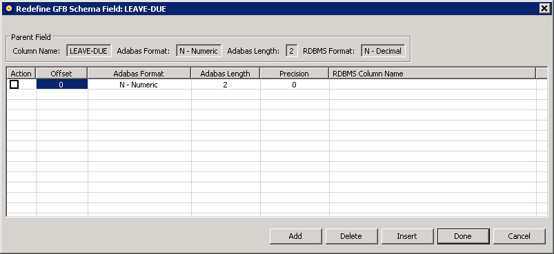
You can tab or click in the cells of this table of child fields, as needed, to alter the child field settings.
In the table, change the length of the first child field in the associated Adabas Length field, to accommodate additional child fields. If you do not do this, you can only specify a single child field (since the lengths of the child fields cannot exceed the length of the parent field). In addition, you must specify the column name for the child field in the RDBMS Column Name field.
Optionally, adjust the format (Adabas Format field) and offset (Offset field) of the child field in the table.
If the field is numeric or packed, use the Precision field to adjust the number of digits that appear to the right of the decimal point for the field.
Maintain additional child fields, as necessary, in the table of child fields.
For every child field you define, you must specify a length and an RDBMS column name. If you do not specify an offset for a child field, the Data Mapping Tool automatically calculates it based on the lengths of the other child fields. If you do not specify a field format for a child field, the format of the parent field is assumed.
To add a child field, click the button. A new blank child line becomes editable in the table.
To insert a new child field between two fields already in the table, select the Action box (check it) of the lower child field and then click the button. A new blank child line is inserted between the two existing child fields and becomes editable in the table.
To delete a child field from the table, select the Action box (check it) of the child field and then click the button. The child field is removed from the table.
When all child fields have been specified in the table, click .
The field appears as redefined (split) in the GFB schema. When the GFB and associated field table are generated, the redefined field will appear as multiple columns in the resulting RDBMS table.
To undo a schema field redefinition:
Right-click on the name of the schema field whose redefined properties you want to undo in the GFB Schema column of the main Data Mapping Tool window.
GFB schema field names are shown in the list prefixed by
the icon .
A drop-down menu appears.
Select from the drop-down menu.
The Redefine GFB Schema Field:fieldname dialog appears, listing the GFB schema field you can redefine and its child entries. In the following sample, the parent field, PERSONNEL-ID, has been split into three child fields: Division Code, Branch Code, and Sequence Number.
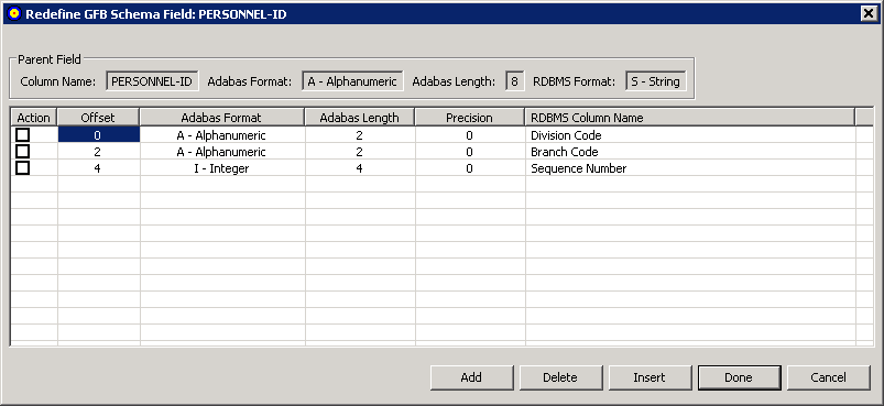
For each child field, select the Action box (check it) and then click the button. The child field is removed from the table.
Click .
The child fields are removed from the GFB schema and the parent field is no longer redefined (split). When the GFB and associated field table are generated, the parent field will appear as a single column in the resulting RDBMS table.
By default, the ISN (internal sequence number) is the primary key of every record in the GFB schema. However, the Data Mapping Tool allows you to change the primary key of the table in the schema and it allows you to select multiple keys to be used as a composite key for the table.
Key fields in the schema are prefixed by the icon
 .
.
Notes:
This section covers the following topics:
To change the primary key:
Right-click on the name of the schema field that you want to make a primary key in the GFB Schema column of the main Data Mapping Tool window.
GFB schema field names are shown in the list prefixed by
the icon .
A drop-down menu appears.
Select from the drop-down menu.
The schema field you selected becomes the primary key for the table. If the ISN field was the primary key prior to this change, it is no longer listed in the schema.
A composite key is key that is comprised of multiple fields in the schema. Any field except the ISN field and redefined (split) fields can be used in a composite key.
Note:
Installations wishing to create composite keys must have
Event Replicator for Adabas 3.2.1 or later installed.
To create a composite key:
Right-click on the name of a schema field that you want to make part of a composite key in the GFB Schema column of the main Data Mapping Tool window.
Note:
At this time, the Event Replicator Target Adapter does not support the use of
MU or PE fields as primary keys or in composite keys.
GFB schema field names are shown in the list prefixed by
the icon .
A drop-down menu appears.
Select from the drop-down menu.
The schema field you selected becomes a key for the table. If the ISN field was the primary key prior to this change, it is no longer listed in the schema. The ISN field cannot be used in a composite key.
Repeat steps 1 and 2 for any additional fields you want to included in the composite key.
All fields you have identified as key fields are
combined to create a composite key and are prefixed by the icon
in the schema.
Read Changing the Composite Key Order for information on how to specify the order of the fields in the composite key.
By default, the order of the fields in a composite key is the same as the order of the original primary key selection.
To change the order of the fields in a composite key:
Right-click on the name of any of the schema fields that comprise the composite key in the GFB Schema column of the main Data Mapping Tool window.
Key field names are shown in the list prefixed by the
icon .
A drop-down menu appears.
Select from the drop-down menu.
The Set Composite Key Order dialog appears.
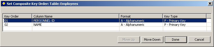
You can reorder the fields in the composite key using the Set Composite Key Order dialog. Simply select the field you want to move (click on it) and click the or buttons until it is placed where you want it.
When all composite key fields are in the order you want, click .
The dialog closes and the composite key order is logically updated. Any subtables containing foreign and primary key references are updated to show the new composite key order.
To remove the primary key specification for a field in the
table:
Right-click on the name of the schema field that you want to remove as the primary key or remove from a composite key in the GFB Schema column of the main Data Mapping Tool window.
Key field names are shown in the list prefixed by the
icon .
A drop-down menu appears.
Select from the drop-down menu.
The schema field you selected is no longer a primary key for the table. If no other primary key is defined for a table, the ISN field appears as the primary key.
You can review the proprieties of a GFB schema.
To review a GFB schema's properties:
Right-click on the name of the schema whose properties you want to review in the GFB Schema column of the main Data Mapping Tool window.
GFB schema names are shown in the list prefixed by the
icon .
A drop-down menu appears.
Select from the drop-down menu.
The Properties: GFB Schema: schemaname dialog appears, listing the GFB schema properties.
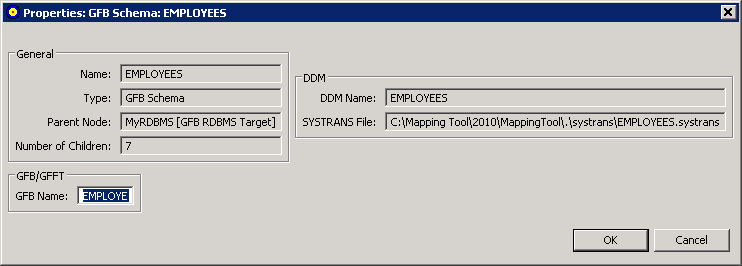
Most of the fields in this dialog are read-only. However, you can specify the name of the GFB that should be used if you upload a GFB/GFFT that has been generated from this schema to a Replicator system file. By default, the GFB name is the first seven characters of the GFB schema. You can change it on this screen or when you perform the upload.
For more information about uploading generated GFBs/GFFTs to a Replicator system file, read Uploading a Generated GFB/GFFT to a Replicator System File.
Click when you are done reviewing the properties.
At any time that you are working with the GFB schema, you can save it.
To save the GFB schema:
Select the option on the menu.
Or:
Click on the
button on the Data Mapping Tool main window.
The schema is saved in the location identified in the Data Mapping Tool preferences. For more information, read Managing the Mapping File Location.
You can remove a GFB schema from the Data Mapping Tool (for example, if you want to start over).
To rename a GFB schema once it is generated:
Right-click on the name of the schema you want to remove from the GFB Schema column of the main Data Mapping Tool window.
GFB schema names are shown in the list prefixed by the
icon .
A drop-down menu appears.
Select from the drop-down menu.
The GFB schema is removed.
Once you have created a GFB schema, you can generate a GFB and field table (GFFT). The generated GFB and field table file can be uploaded to a Replicator system file or saved as input to an Event Replicator RPLOD utility run. Additional information on saving or importing the generated GFB/GFFT is provided elsewhere in this section.
To generate a GFB and field table, complete the following
steps:
Create a GFB schema as described in Creating and Maintaining the GFB Schema.
If desired, save the GFB schema by clicking on the
button or the
button on the Data Mapping Tool main window or
by clicking on the option on the
menu.
Right-click on the name of the GFB schema in the GFB Schema column of the Data Mapping Tool main window.
The GFB schema name is prefixed by the icon
.
A drop-down menu appears.
Click on the option on the drop-down menu.
Or:
You can also select the option on the menu.
The GFB and field table (GFFT) are generated and the Generate GFB/GFFT dialog appears.
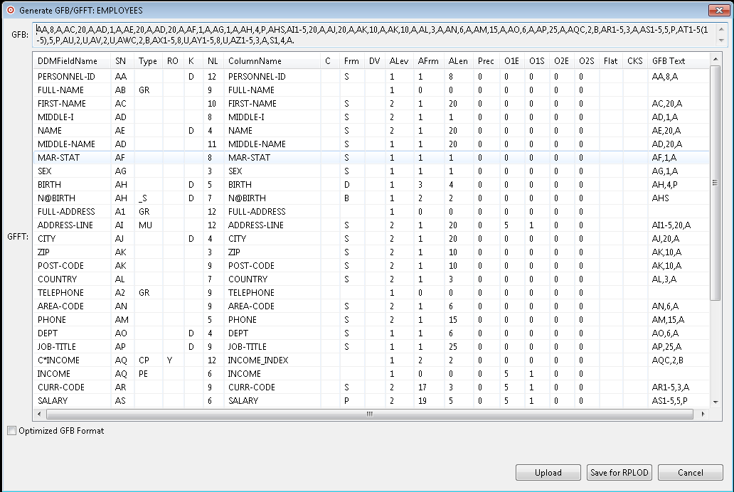
You can use this dialog to review the generated GFB/GFFT.
Optimized GFB Format: Check this box to generate the GFB/GFFT in optimized format.
Once the GFB/GFFT is generated, you can perform any of the following actions.
You can upload the generated GFB/GFFT to a mainframe Replicator System file. For more information, read Uploading a Generated GFB/GFFT to a Replicator System File.
You can save the generated GFB/GFFT to a text file for use with the Event Replicator RPLOD utility. For more information, read Saving a Generated GFB/GFFT for the RPLOD Utility. For information on using the RPLOD utility, read RPULD and RPLOD Utilities
You can upload the generated GFB/GFFT to a Replicator system file. To do this, you must have an active Entire Net-Work running with a TCP/IP driver (Entire Net-Work TCP/IP Option) running on the mainframe node where the Event Replicator Server is located.
To upload the generated GFB/GFFT to a Replicator system file,
complete the following steps:
Verify that the Event Replicator Server with the Replicator system file you want to upload the GFB/GFFT to is started.
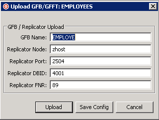
Click on the button on the Generate GFB/GFFT dialog.
The Upload GFB/GFFT dialog appears:
Note:
This dialog is initially filled with values specified for
it in the GFB/GFFT options of
your Data Mapping Tool preferences.
Supply valid values for all fields on the Upload GFB/GFFT dialog, as described in the following table. Values are required for all fields on the dialog.
| Field Name | Description |
|---|---|
| GFB Name | The seven-character name of the
generated GFB. If the name you select for the generated GFB already exists in
the Replicator system file, you will be prompted to change it before it is
overwritten.
Note: |
| Replicator Node | The network node where the Replicator system file can be found. This is the TCP/IP node or IP address where the Event Replicator Server nucleus resides. |
| Replicator Port | The port number where the Replicator system file can be found. This is the TCP/IP port number used by the Entire Net-Work TCP/IP Option on the mainframe. |
| Replicator DBID | The Event Replicator Server database ID. This is the database containing the Replicator system file to which you want to upload the generated GFB. |
| Replicator FNR | The Replicator system file number within the Event Replicator Server. |
When values have been supplied for all fields on the Upload GFB/GFFT dialog, click on the button to perform the upload. To cancel the upload, click on the button.
Use the button to save the Replicator upload parameters you have specified. This will override the parameters you have specified in the Data Mapping Tool preferences. For more information about setting GFB/GFFT preferences, read Managing Your GFB/GFFT Upload Definition.
If the button was selected, the parameters are saved as your new preferences and the Upload GFB/GFFT dialog remains open.
If the button was selected, a progress dialog appears showing the progress of the upload. You can click on the button on the progress dialog to cancel the operation at any point. Canceling the operation will remove any partially stored GFB/GFFT and will restore any existing GFB/GFFT being overwritten.
When the upload is complete, the status bar of the main window will show confirmation of the upload, including statistics regarding the number of records uploaded and the duration of the upload.
You can create a text file of the generated GFB/GFFT that can be used as input to the Event Replicator RPLOD utility. For more information about the utility, read RPULD and RPLOD Utilities.
To save the generated GFB/GFFT to a text file for the RPLOD
utility, complete the following steps:
Click on the button on the Generate GFB/GFFT dialog.
A Save GFB/GFFT for RPLOD dialog appears, allowing you to specify the name of the GFB text file and its directory location.
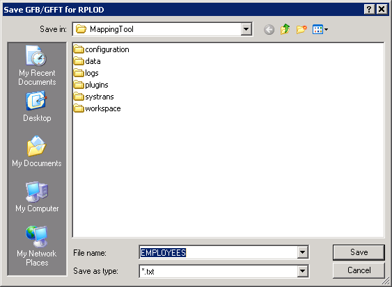
Using this dialog, navigate to the correct directory, specify a file name and click . If you want to cancel the operation, click .
If the button was clicked, the GFB/GFFT text file is saved at the specified location.
Once the text file has been saved, you can move the file to the mainframe using traditional FTP or directly using products such as Software AG's Entire Connection. Once it is transferred to the mainframe, you can set up an RPLOD utility run using the statements in the text file.