Screen diagram
A screen diagram describes screens used in software development. The aim is automatic derivation of screens from the screen diagram.
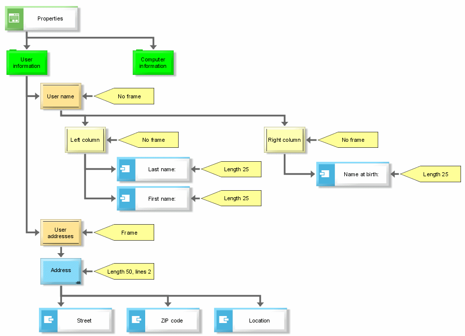
Thus, screen diagrams display the structure and to a certain degree the functionality of screens. From left to right and top to bottom, the screen diagram's structure corresponds to the geometry of the interface described.
The central symbol is the 'screen', which corresponds to a window in Windows terminology. This window can have multiple tabs (Page symbol). In general, the interface can be divided into areas using a table format (Section symbol for a row, and Column symbol for a column). The Section and Column symbols can be nested as required in order to form complex interfaces. You can place tables (Screen table symbol), text entry boxes (COT attribute symbol), graphics (Bitmap symbol), and text descriptions (Text symbol) on the interface. Using the Layout symbol you can assign representation properties to the Screen, Page, Section, Column, Screen table, COT attribute, and Text objects.
Additional symbols can be used to describe the screen interface.
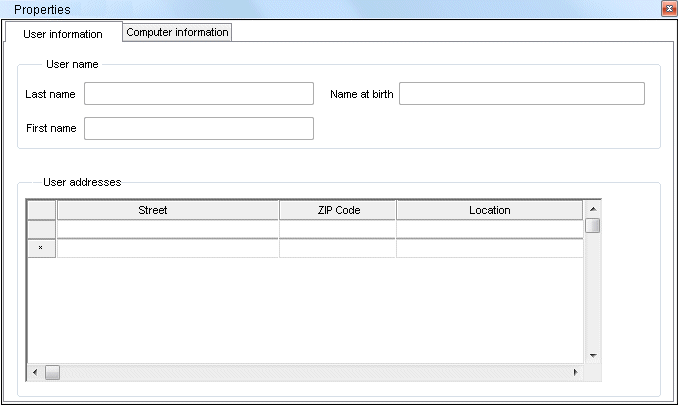
The following figure shows an example of a screen diagram. The second figure illustrates the screen derived from the diagram.


