Linking functions with data
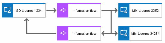
To show which data are exchanged between application systems, information flow objects can be created between application system objects of the function view. Unlike application system objects at the design specification level, these application system objects are no application system types, but concrete specimens (individual licenses). This means that application systems, modules, and program module types can be interlinked by data flow connections. If you defined at the design specification level that the Sales system SD version 2.1 module type can exchange data with the Material management system MM version 1.2 module type, the implementation level shows that the SD license no. 1234 module exchanges data with the MM license no. 2352 and MM license no. 34234 modules. Both MM modules are of the Material management system MM version 1.2 module type. This is illustrated in the following figure.
To specify the data objects that are exchanged between systems in more detail, corresponding model types of the data view are assigned to the information flow objects.
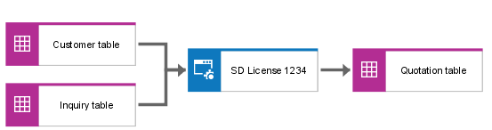
Apart from the data flows between application systems, input/output data can also be specified for every application system. There are two reasons for the relationships to be represented in an access diagram (physical). In the first case, the data objects are objects of the table diagram (table, field, view (physical)) located in the data view of the implementation level. These data objects can be linked to application system objects of the design specification level or implementation level via input/output relationships. In the second case, the application system objects are concrete application systems or modules of the implementation level, which are linked to objects in the data view.
Therefore, the following general rule can be defined:
If one of the object types participating in an input/output relationship originates from the implementation level of the relevant view, the relationships in the process view are represented at the implementation level (access diagram (physical)), as well.
An example is shown in the following figure.