Network diagram
The network diagram illustrates the realization of the network topology defined in the design specification.
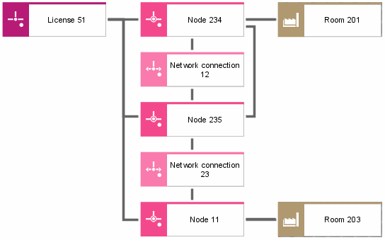
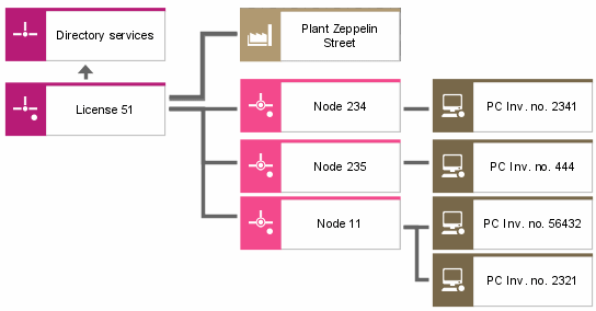
The networks that exist in the company are recorded by means of the Network object. It is possible to specify for each network the network nodes and network connections it consists of.
The exact location of every network, network node, and network connection within the company can be indicated. A location can be an entire plant, a specific building, a complex of buildings, an office, or an individual workstation.
The network diagram also records the hardware components used to realize each network connection and network node. Besides, it is possible to illustrate the structure of every single hardware component. On the one hand, hardware components are used to form network connections and network nodes; on the other hand, they can be connected to network nodes. This relationship can be represented in the network diagram, as well. For every object of the specimen level, the relationship to the corresponding object of the design specification level can be modeled. This way it is possible to express, for example, that the network in the Port St. plant is of the FDDI ANSI X3.139 type.
Thus, the network diagram establishes the links to the design specification via type allocations, as well as the links to the requirements definition via the allocation of network components to specific locations.
A list of object and relationship types that are available in a network diagram is provided in the ARIS Method – Tables manual (ARIS Method tables.pdf) on your installation media.