Working with Decision Trees
A decision tree is a decision entity. It uses a tree-like structure to depict a complex set of rules in a IF Condition THEN Result syntax.
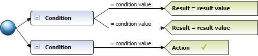
Decision Tree Structure
A decision tree consists of nodes and links. A node can represent the root, a condition (blue color), an assignment result and its assigned result value (green color), or an action result and its action status (green color). A link can be a root link or a condition link. A root node can be linked to one or more condition nodes, and a condition node can be linked to one or more condition nodes or result nodes.
The following table gives an overview of the decision tree elements and their graphical representation:
Element Name | Graphical Representation | Description |
Root Node | | The root node is the root of the decision tree. All decision branches start from here. |
Root Link | | A root link connects the root node with a condition node on the first level. A root link represents an unconditional branch to a condition node and is not evaluated. |
Condition | | A condition node contains a reference to one input or input/output parameter element. Condition links can branch off of this node. |
Condition Link | | Three types of condition links exist:  Condition link that contains an operator and a condition value. It represents a conditional branch to the element on the right side of the condition line when the condition evaluates to true. Condition link that is left empty. It represents an unconditional branch and is not evaluated. Tree evaluation continues with the successor node, if there is any. Otherwise condition link. It contains the otherwise operator and a condition value, and it represents the last branch of a condition node. Its path is taken if none of the previous branches from the parent condition evaluate to true. The following types of condition values exist: Literal value. Value range. Parameter element (marked by a dotted line). Action that delivers an output value (marked by a dotted line and () behind the action name). Constant (marked by a dotted line). Expression. |
Assignment Result Node | | An assignment result node contains a reference to one output or input/output parameter element, an operator and the assigned result value. The followign types of result values exist: Literal value. Value range. List. Parameter element (marked by a dotted line). Action that delivers an output value (marked by a dotted line and () behind the action name). Constant (marked by a dotted line). Expression. Assignment result nodes can be chained together along with action result nodes. |
Action Result Node | | An action result node contains a reference to the action that is to be invoked and one of the following action statuses:  (action is enabled).  (action is disabled). Mapping can be specified. Action result nodes can be chained together along with assignment result nodes. |
Example
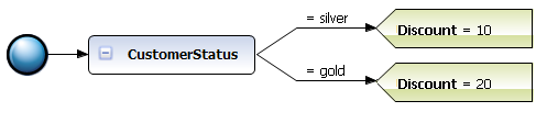
The following rules can be modeled in a decision tree:
Rule 1: | IF a customer has customer status silver, THEN this customer gets a discount of 10%. |
Rule 2: | IF a customer has customer status gold, THEN this customer gets a discount of 20%. |
The decision tree uses one condition node with two condition values, and two assignment result nodes:
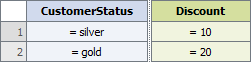
This decision tree corresponds to the following decision table: