Design specification - Network topology
The company's organizational structure as represented in the organizational chart can now be supported using communication and information system infrastructures. The structural requirements for these information systems can generally be defined in the design specification in the form of network topologies.
In a first step, various network types can be incorporated in a Network topology model.
A network type typifies individual network specimens that are based on precisely the same technology.
The following figure shows an example of a network type:
Network types can be interlinked and, since they are logical constructs, they can also be arranged in a hierarchy.
Network node types and network connection types can be assigned to every network type. Thus, technological restrictions resulting from the choice of one particular network type for a company can be identified immediately. It is possible to show for every network connection type which network node types it may end in.
When speaking of hardware component types, the term may refer to either network hardware for implementing the defined network structures, or hardware component types that can be connected to network node types.
As with application system or network types, hardware component types do not represent individual specimens of hardware components that can be identified, for example, by inventory numbers assigned by the company. Instead, they typify all hardware components that are based on the same technology. Hardware component types may be arranged in any required hierarchy.
A hardware component type typifies individual specimens of hardware components that are based on precisely the same technology.
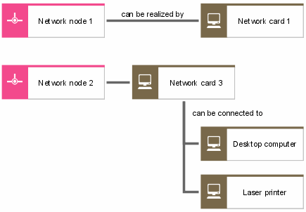
Together with network node and connection types, a kind of reference model of the network topology can now be created. This model indicates which hardware component types can be used for realizing specific network connection types or network node types. An example of a connection type might be a particular type of transmission cable. Besides, it is possible to show which hardware component type can be connected to which network node type. Network node types may also have relationships to hardware component types that are used to create node types. An example is shown in the following figure.
The link between network topology and the objects of the requirements definition is established via two approaches.
On the one hand, for every single hardware component type the organizational unit or position responsible for it can be specified.
On the other hand, it is possible to define for each network type, network node type, network connection type, and hardware component type at which location within the company they may be found. Thus, the location is the central link between the requirements definition and the design specification of the organization view.
A list of object and relationship types that are available in a network topology model is provided in the ARIS Method – Tables manual (ARIS Method tables.pdf) on your installation media.


