Relations diagram and Attribute allocation diagram
In the design specification, the logical data structures designed in the requirements definition are transformed into a form of description that concrete database systems can be based on. ARIS provides the relations diagram for this purpose.
The relations diagram and the attribute allocation diagram are available to define existing relations and attributes including their relationships to the information objects introduced in the requirements definition.
In a first step, the required relations are defined in the relations diagram.
A relation describes an entity type through its attributes. A relation is a subset of possible value range combinations of individual attributes.
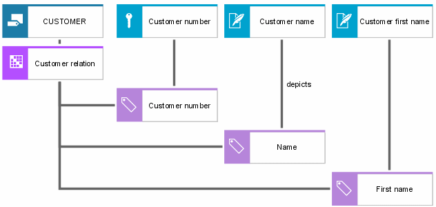
Relations are shown in graphical form as follows:
Every eERM entity type now constitutes a relation in the relations diagram. When realizing relationship types of an eERM, the cardinality is a very important factor in deciding whether or not to create a separate relation for the relationship type. Unlike 1:n relations, n:m relations must be represented in separate relations.
In a second step, the relations diagram can indicate for each relation which entity type or relationship type of the eERM it represents.
A relation can be specified in more detail by listing its attributes. Whether the corresponding attribute serves as a key attribute, foreign key attribute, or descriptive attribute may be defined by specifying the relevant connection when linking the relation and the attribute. Also, the relationship of every single attribute to the ERM attribute of the requirements definition it illustrates can be established.
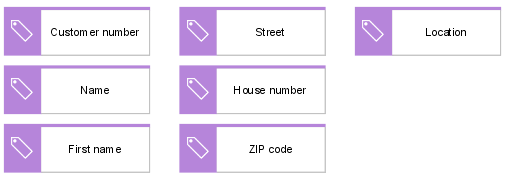
To reduce representation complexity, the attributes of every relation can be defined in an attribute allocation diagram that is linked to the relation. An example is shown in the following figure.
Cluster/Data models of the requirements definition are realized in the design specification by a separate object type called View. Based on the definition of Cluster/Data models, View is defined as follows:
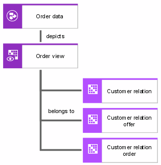
A View is the logical view of multiple relations.
Assignments of relations to a View can also be shown in a relations diagram.
1:n relationships of the ERM are not represented by separate relations in the relations diagram. The relationship is illustrated by integrating the key attribute of the superior entity type into the relation of the subordinate entity type. In this process, the original key attribute becomes the relation's foreign key.
A connection can be used in the relations diagram to show which attribute of the relations diagram illustrates the ERM's relationship type.
A list of object and relationship types that are available in a relations diagram is provided in the ARIS Method – Tables manual (ARIS Method tables.pdf) on your installation media.


