API Gateway Deployment Scenarios
API Gateway enforces threat protection, policies and routing capabilities for APIs. This section describes high-level API Gateway architecture for various deployment scenarios.
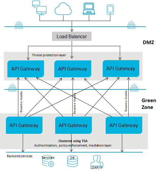
Deployment scenario 1: Paired gateway deployment
This setup consists of:

One or more standard edition
API Gateways for threat protection and connected to a load balancer in DMZ.

One or more advanced version
API Gateways clustered in the green zone to enforce policies and provide routing capabilities. You can have multiple instances of
API Gateways connected through a load balancer and clustered using Terracotta Server Array. You can add an extra layer of protection by using reverse invoke.
A firewall protects the API Gateway infrastructure in the paired deployment. You can add an extra layer of protection by using reverse invoke. The API Gateways communicate between the zones using the reverse invoke approach.
The following diagram provides an architectural overview of the paired gateway deployment:
Note:
If you have multiple instances of API Gateway connected using a load balancer for threat protection and you change the enforced rules on one of the API Gateway instances, you must restart the other instances to synchronize the rule enforcement across all the API Gateway instances.
To learn how to configure threat protection and invoke an API using REST API, read the
API Gateway standard edition in DMZ & API Gateway advanced edition in Green zone section from the
Threat protection in API Gateway article.
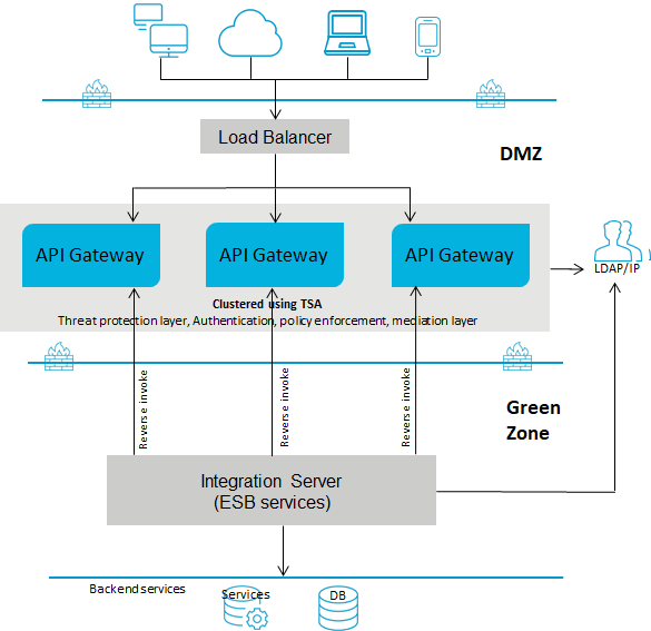
Deployment scenario 2: API Gateway in the DMZ with reverse invoke configuration
This setup consists of:

One or more advanced edition
API Gateways clustered and connected to a load balancer in DMZ. You can have multiple instances of
API Gateways connected through a load balancer and clustered using Terracotta Server Array. A single
API Gateway is used for enforcing authentication and routing capabilities.

The ESB services in
Integration Server reside in the green zone behind the firewall.
If you use reverse invoke for communication between
API Gateway and the internal ESB, ensure that the endpoint in the routing policy applied is configured as apigateway://
registrationPort-aliasname/
relative path of the service. For details, see
Ports and
Routing.
The following diagram provides an architectural overview of the API Gateway deployment in a DMZ for webMethods customers:
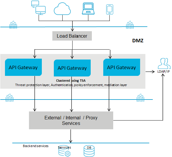
Deployment scenario 3: API Gateway with a Load Balancer in the DMZ
This setup consists of:

One or more advanced edition
API Gateways clustered and connected to a load balancer in DMZ. A single
API Gateway is used for enforcing all policies or rules. You can have multiple instances of
API Gateways connected through a load balancer and clustered using Terracotta Server Array.

The native services reside in the green zone behind the firewall. As the native services are directly invoked, you must open the native service port to the gateway network.
The following diagram provides an architectural overview of the API Gateway deployment for non webMethods customers:
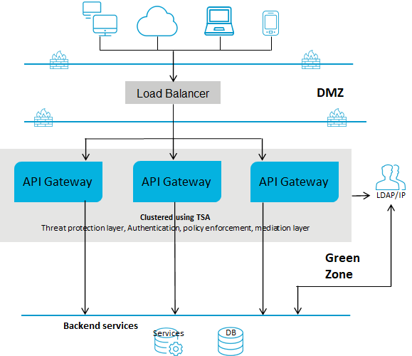
Deployment scenario 4: API Gateway in the green zone with a Load Balancer in the DMZ
This setup consists of:

One or more advanced edition
API Gateways clustered in the green zone and connected to a load balancer in DMZ. A single
API Gateway is used for enforcing authentication and routing capabilities. This deployment does not require threat protection. However, you can configure and enforce threat protection, if required. You can have multiple instances of
API Gateways connected through a load balancer and clustered using Terracotta Server Array.

The ESB services in
Integration Server reside in the green zone behind the firewall. Because the
API Gateway and the ESB services reside in the green zone, the ESB services are directly invoked.
The following diagram provides an architectural overview of the API Gateway deployment in the green zone for webMethods customers:


