Design specification - Application system type diagram
The design specification of the function view contains the specification for the application system and module types, as well as the modular structure of the application system type, an outline of individual transaction steps, and the definition of input and output presentations in the form of draft lists and screen designs.
Key questions to which the design specification of the function view provides answers are:

How can application system types, module types, or IT functions support the functions defined in the requirements definition?

What is the modular structure of application system types or module types?

Which lists and screens are required to carry out a function?

Which lists can be created with an application system type or a module type, and which screens do application system types and module types use?

What technology (operating system, user interface, database management system) is an application system type based on?

Which business objectives are pursued when a specific application system type is used?
Thus, the Application system type is the key object type of the function view's design specification.
Unlike concrete application systems that come into play only at the implementation level of the function view and that represent specific, identifiable (for example, by a license number) application systems within a company, application system types are generated as the result of typifying all application systems that are based on precisely the same technology.
An application system type typifies individual application systems that are based on precisely the same technology.
Example: ARIS Architect is an application system type. You can purchase several licenses for this application system type and thus obtain various individual application systems.
Application system types are represented by the following graphic symbol:
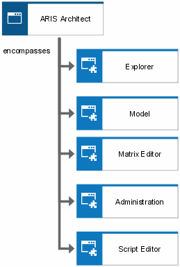
Application system types are mostly modular in structure. The application system type diagram is a means of representing this modular structure. Application system types are broken down into module types. The following figure shows an example:
In the above example, ARIS Architect consists of the module types Explorer, Model, Matrix Editor, Administration, and Script Editor. As with application system types, module types typify individual modules that are based on precisely the same technology. Module types are components of application system types. They are capable of autonomous operation.
A module type is a component of an application system type, which is capable of autonomous operation. Module types typify individual modules that are based on precisely the same technology.
Application system types and module types can be arranged in any hierarchy. At the lowest level, module types can be divided into IT function types.
An IT function type, in the sense of a transaction, is the smallest unit of a module type. IT function types are realized as individual program modules and must always be carried out completely to process an individual work step.
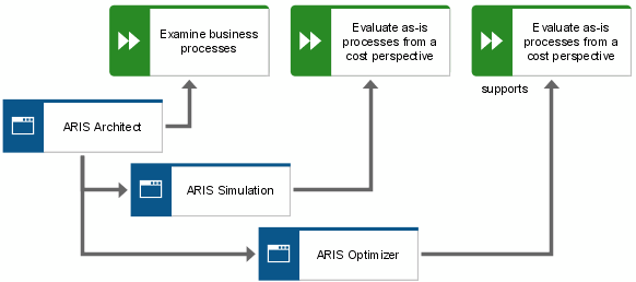
The application system type diagram is also a means of defining the functions of the requirements definition that are supported by the specified application system types and module types. This assignment forms the link between the requirements definition and the design specification of the function view. The following figure shows an example.
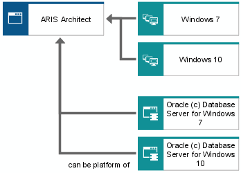
To obtain a more detailed specification of the technology that application system types and module types are based on, it is possible to allocate to them the types of user interfaces, database management systems, and operating systems under which they can run, as well as the programming languages that are used to implement them. As this concerns types and not concrete specimen, multiple relationships are possible. For example, an application system type can be assigned the Windows 7 and Windows 8 user interface, which means that the application system type can run under both user interfaces. A unique relationship is required only when the graphical user interface is assigned to a concrete specimen (that is, a specific application system) at the implementation level of the function view. This relationship describes the exact configuration of the application system type license that the company purchased.
An example of possible assignments in an application system type diagram is shown in the following figure.
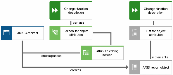
Processing a technical function with the support of an application system involves the use of various screens and the creation or use of various lists provided by the corresponding application system. For this purpose, the List and Screen objects are available and can be assigned to either the technical function or the application system types and module types.
If, in a first step, general operational procedures are to be defined without reference to specific application system types, the Draft list and Screen design objects can be used to specify the required screens and lists. First, both object types specify in general which type of list or screen is to be used (for example, Enter customer data), without establishing a specific reference to application system type lists or screens. Subsequently, these draft lists and screen designs can be assigned to specific lists and screens. Existing assignments determine possible implementation scenarios. The following figure illustrates an example.
A list of object types and relationships that are available in an application system type diagram is provided in the ARIS Method Reference manual on your installation media.


