Linking organization with data
The focus is on the same questions dealt with in the design specification:

Which organizational units are responsible for data objects?

Who has access to which data objects?

Which data objects are stored on which hardware components?
Unlike the relationships in the design specification, the relationships established here form a link to the data objects shown at the implementation level of the data view.
This means that the responsibility for data objects is defined for relations and attributes for the physical structures, that is, tables, fields, and their specimens [table (specimen), field (specimen)].
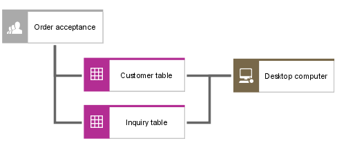
To represent these dependencies, connections are drawn in the access diagram (physical) between the objects of the organization view (organizational unit, position, person, etc.) and the table diagram's objects mentioned earlier (table, field, view (physical), etc.).
When a connection is drawn between organizational units and tables and fields, the meaning of each relationship must be defined individually. For example, is responsible for means that an organizational unit is responsible for the contents of the relevant table or field, while accesses means that a position or person has access privileges for the data objects shown.
In addition to defining access privileges and responsibilities, you can use the hardware component object (organization view/implementation) to define on which of the available hardware components - which can be uniquely identified by the inventory number, for instance - certain information objects of the company are located. For this purpose, the Hardware component object may be linked to information objects of the implementation level (tables, fields, etc.), the design specification level (relations, attributes), or the requirements definition level (entity types, cluster/data models, etc.) in the access diagram (physical).
The figure below illustrates an example.
