
An ApplinX Procedure is a well-defined encapsulation of a complete process, and contains process input arguments, process output arguments and the process definition itself. A procedure group is a container of several procedures. In ApplinX, Procedure Groups are equivalent to Web services, and Web methods that implement these Web services are called Procedures. Using Procedures, any enterprise application can retrieve information from a host application and input data to a host application. There are a number of procedure types in ApplinX:
Path Procedure: encapsulates a process of navigation in host screens, collecting data or submitting data.
Flow Procedure: encapsulates a complex process that can combine host sessions and other data sources: databases, host transactions (RPC), other web services.
Web Procedure: encapsulates a process of navigating and selecting elements in the Web.
Program Procedure: encapsulates a host transaction (in COBOL or RPG), invoked via RPC and not via the screens layer.
External Web Services: encapsulates a non-ApplinX web service, invoked via SOAP.
Procedures can be exposed for external use using Web services, procedure clients and ApplinX Base Object.
The Path procedure is similar to the Flow Procedure. To know which one to use, ask yourself the following:
Do you need to encapsulate a transaction from a single host session (this is the most common case)? Use a Path procedure.
Do you want to execute the encapsulated transaction from the ApplinX Base Object API (ABO)? Use a Path procedure.
Do you need to integrate data from different sources, such as database, several host sessions, external web services or RPC-based sessions? Use a Flow Procedure.
Do you need to integrate data from the Web? Use Web Procedures.
Path procedures on the one hand allow navigating between host screens and can be used for navigation, data gathering or transaction execution on a single host session. On the other hand, it is a Procedure, and can therefore be activated as a Web service operation, using a generated procedure client or called by another flow procedure. Procedures, provide a rich variety of logical nodes and expressions that make the host navigation very flexible without needing client side code.
A Path procedure can be created either via the Session or the Repository. When creating the Path procedure in the Session, you use the Path toolbar to record the path and then you can edit the path in the Path procedure dialog box. When creating the Path procedure via the Repository, you need to manually define the Path procedure using the available nodes. It is recommended to create the Path procedure via the session and then fine-tune and handle errors.
 To create a Path Procedure via the Session View
Navigate to the first screen from which you want the recording to commence.
Click Record on the Toolbar.
Navigate to the various screens to record the relevant path.
Click on the Define Inputs icon to mark all the unprotected input fields in purple. Click on one of the marked fields to define it as an input. The field will be marked orange.
Click on Define Procedure Outputs to mark all the protected and unprotected fields. Click on a field to define it as an output in the Path procedure. The field will be marked blue.
If you want to record a step that repeats again and again until a certain condition is reached, click the loop icon, and follow the instructions in the wizard. This kind of definition can be applicable for collecting data of a host table.
To end a recording click Stop . The End Path Recording dialog box is displayed.
Enter a name for the path, and click Finish. The Editor will open where you can manually edit and add nodes.
Refer to the Procedures section for more information about Procedures.
To create a Path Procedure from Repository
Create a new Path Procedure via File>New>Other...>Software AG >Entities>Procedure.
The New Path procedure wizard is displayed. Enter a name for the Path procedure.
Define inputs and outputs in the bottom panel of the screen.
Define nodes. It is recommended to always create a Try/Catch node in order to catch exceptions within the procedure.
Note:
An image of the Procedure tree can be saved as a PNG file for
later reference, by right-clicking on the Procedure root node, and selecting
.
Save the procedure.
Right-click on the procedure in the ApplinX Explorer and select Run to run and test the procedure, or select Debug to open the Debug window and debug the procedure.
To Convert Old Paths or Path Wrappers to Path Procedures
Old Paths are deprecated and are completely replaced with Path Procedures. Old Paths can still be used in runtime but cannot be edited or updated. Paths created in previous ApplinX versions will require conversion to the new Path Procedures using the conversion tool (right-click on a Path and select Convert).Refer to Migration for further details.
This section provides tips and methodologies that may be helpful when incorporating Path Procedures in your application.
When executing Path Procedures, you may require retrieving field attributes or screen properties. One example for this may be collecting all positive values from a numeric list where all positive numbers are colored green and negative numbers are colored red. Another example is when submitting certain values to the host a modal window may appear which would require us to perform a slightly different navigation than usual.
The required field attributes and screen properties can be retrieved using the "Field Attributes" and "Screen Properties" expressions.
To retrieve field attributes and screen properties:
Right-click on the Expressions node in the mapper area, or if you are creating a condition, click on the Expr link and select Screen Data>Field Attributes/Screen Properties.
When working in a Mapper area, map the attribute or property to the appropriate variable.
From within a condition, select the relevant attribute or property.
When you need to search for a specific value within a host table that spans over several screens, what you actually need to do is to search for a specific value within a multiple field. A possible scenario may be, for example: A web page that contains a table with data collected from several screens. When clicking on a specific line, you would like to drill down and see additional details. The problem is having collected several screens on one web page, the selected line doesn't appear on the current host screen anymore - you need to look for it. In your ApplinX session, you need to scroll through the table again, and look for the particular data or a unique ID from the selected line on the web page. In order to do this, your Path procedure requires two loops: One loop, to scroll through the table and another loop, to search each line for the selected value.
This can be implemented using the Find Field Index function. This function allows you to check a single condition within a multiple field, testing each field and returning the index of the first field that matches the condition.
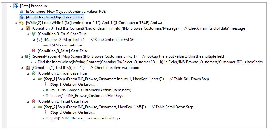
The loop will continue iterating through the table as long as both of these conditions are met:
The itemIndex parameter is set to -1. This means no
match to the search value has been found yet.
The isContinue parameter is set to True. This parameter
will be set to false when the end of the table is reached. This will prevent
creating an infinite loop when no match is found.
The loops are defined as follows (see screen capture above):
The [Condition_3] condition checks whether you have reached the end of the table. When the end of the table is reached, IsContinue is set to False.
Configure the Find Field Index parameters:
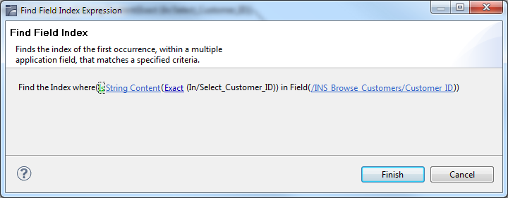
Attribute type: Select an attribute type, in this case String Content. Other possible attributes include: protected, hidden, intensified, reversed video, background color, foreground color, blinking or underlined.
Select comparison type: You can check whether a string value is part of the field content or you can look for an exact match. Numeric values can be compared (less than, equals, greater than, etc) to the field's numeric value.
Select the screen and multiple field whose content you wish to check.
Using Find Field Index, [ScreenMapper_4] searches for the value inside an entire table column (multiple field) and maps the result (the matched index) to the itemIndex parameter previously created. When no result is found, the mapping is not performed.
The [Condition_1] condition checks whether a match was found by checking if itemIndex is bigger than -1 (which means a result has been found). If a match was found, use itemIndex to implement a drill down action. If a match was not found, perform a scroll down action to continue the search.
ApplinX enables generating a log that includes debug data regarding procedures that fail in runtime. The log includes a snapshot in ASCII characters of the screen that caused the failure.
To log data regarding procedures that fail in runtime
In the <APPLINX HOME>/config/log/gxlog_config.xml file under the com.sabratec.util.flow.error_tracking category tag, change the <level value="off"/> line to be commented and uncomment the <!-level value="debug"/--> line.
Restart the ApplinX Server.
The log will be created in the <APPLINX HOME>/log directory, and the file names will have the following format: debugging_error_in_%I_%t.log, %I being identifying information about the user and procedure name, and %t being the timestamp. The location and name of the file can be changed in the gxlog_config.xml file.
Flow Procedures are available only for SOA licensed ApplinX servers. They are able to execute other types of ApplinX procedures in addition to being able to connect to databases and perform operations such as SELECT, Execute, Commit and Rollback. This allows retrieving data from sources other than host-screens.
When creating a new flow procedure, it is important to first define your goals and what tools you need in order to reach these goals. These tools may include paths or Data Structures (that represents inputs or outputs), programs or a database.
To create a Flow Procedure
Create a new Flow Procedure via File>New>Other...>Software AG >Entities>Procedure.
Define inputs and outputs in the bottom panel of the screen.
Define nodes. It is recommended to always create a Try/Catch node in order to catch exceptions within the procedure.
Note:
An image of the Procedure tree can be saved as a PNG file for
later reference, by right-clicking on the Procedure root node, and selecting
.
Save the procedure.
Right-click on the procedure in the ApplinX Explorer and select Run to run and test the procedure, or select Debug to open the Debug window and debug the procedure.
Refer to the Procedures section for more information about Procedures.
The Web Page Integration feature enables simulating web browser activity and exposing it as a standard web service or integrating it with other ApplinX procedures. Web browser activity is simulated within ApplinX by recording and entering/capturing relevant web content using Web browser based tools. The web content is used by the new type of Procedure - the Web Procedure. This Procedure is specifically designed to enable integrating the User Interface (UI) of Web Pages within ApplinX, taking advantage of the flexible and dynamic capabilities incorporated within ApplinX Procedure infrastructure. The Web procedure can be exposed as a service in the same way the existing ApplinX procedures such as Path and Flow Procedures are exposed.
When your network requires defining a proxy, set the proxy Hostname,
Port, Username and Password in the WebProcedureConfig section in
the <ApplinX installation>/config/gxconfig.xml file.
Refer to
Create a new ApplinX application (including host and repository). Note that when creating a new application, you are required to enter a host. If you are only using the Web Page Integration solution, and are not integrating with other ApplinX components, this may seem to you unnecessary. Due to technical limitations, it is currently mandatory to define a host as part of the process of creating an application. As such, we recommend selecting a host from the list of predefined hosts.
You may also want to read more information regarding the following topics:
Web Procedure Nodes including: GoTo URL Node, Web Page Node, Enter Text Node, Select Node and Click Node.
As part of the process of creating the Web Procedure you will record and capture the elements to be used in the Web Procedure. Before creating a new Web Procedure, it is important to first decide and plan what the scenario is that you would like to record, and also determine which elements you would like to capture and later use in the Web Procedure.
To create a Web Procedure and capture the elements from within your
browser session:
Select the relevant application or the Root node of the application.
In the menu, select . The Web Procedure wizard is displayed.
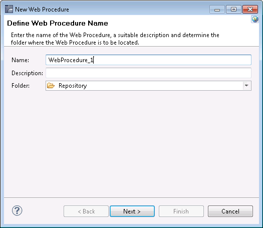
Enter a name for the Web Procedure, a suitable description and determine the folder where the procedure is to be located.
Click Next. The Web Procedure Recorder is displayed. The Recorder is comprised of a customized toolbar, an address bar, the browser area where the Web page content is displayed and a summary of the list of captured elements.
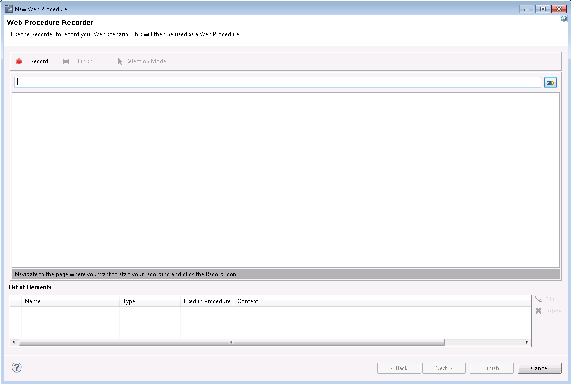
Enter the name of the URL and click the button or press ENTER to navigate to the URL where you would like to begin recording.
Click on the button. When recording there are two possible modes: Navigation mode and Selection mode. Use the Navigate mode to navigate through the web pages as in any Web browser, and record inputs and actions such as clicking on buttons or links, entering data. Every action you do is recorded and can later be edited in the Web Procedure editor.Use the Selection mode to "freeze" the page, so you can capture outputs and inputs, single elements or a list of similar elements. When in the Selection mode, you can no longer navigate to other pages until you return to Navigation mode.
Entering the Selection Mode:
When you want to select and capture elements on a specific page,
click on the button
![]() .
.
Understanding the highlight colors:
Light blue: When you move the mouse over different elements within the browser, the color of the element changes to light blue to indicate that this is the element which will be selected if you now click on this element.
Orange: Once you click on an element, it is highlighted in orange.
Dark blue: Captured elements are colored in dark blue.
Selecting single elements and lists of elements:
Within a page, you can capture either a single element or a list
of elements. When entering the Selection mode, by default, the Recorder is set
to capture single elements, by clicking once on an element. When you would like
to capture a list of elements, click on the List button on the toolbar
![]() , then click on one element
within your list and then on a second element. Before clicking on the second
element, hovering over an element highlights in a light blue color the complete
list of elements that will be captured once you click on the second element.
Ensure that the Single button is pressed in when you wish to select single
elements, and that the List button is pressed in when you wish to select a list
of elements.
, then click on one element
within your list and then on a second element. Before clicking on the second
element, hovering over an element highlights in a light blue color the complete
list of elements that will be captured once you click on the second element.
Ensure that the Single button is pressed in when you wish to select single
elements, and that the List button is pressed in when you wish to select a list
of elements.
Capturing an element:
Click on a required element. The Define Element dialog box is displayed and the element color within the browser changes to orange.
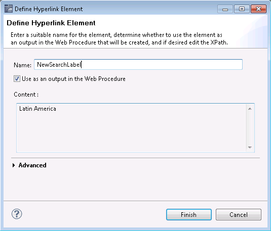
This dialog box may slightly vary according to the type of element captured such as text fields, text areas, passwords, radio buttons, check boxes and drop-down lists, buttons, and hyperlinks.
Defining the captured element:
Provide a suitable name for the element. By default if the HTML element has a name, then this is used by default. If it does not have a name, then the ID is used, and if it does not have an ID then the default is <element type>_<number> (for images, the alt attribute is used). Determine whether this element is to be used as an output/input (depending on the element type) in the procedure (by default the element is selected to be used as the input/output of the procedure, the only exception being when defining a list of elements, when for some types, this check box is not selected by default). The Content area provides a textual display of the captured element (this area does not appear in the Button element).
Understanding the element's XPath:
We use the XPath, the XML Path Language, to locate the element within the Web Page. The wizard tries to suggest the most suitable XPath and in most cases you are not required to make changes. The Advanced section enables you to view the current XPath and if desired change it.
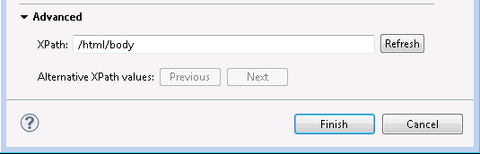
This may be necessary, for example, to ensure a more robust XPath or if the element that is highlighted in the browser is not the desired element. You can scroll through a list of suggested alternative XPaths (using the Previous and Next buttons) or edit and change the XPath yourself. When making changes to the XPath, it is recommended to click on the Refresh button to ensure that the XPath is valid (for more information regarding XPaths, refer to What is an XPath?). This may also change the contents of the Content area.
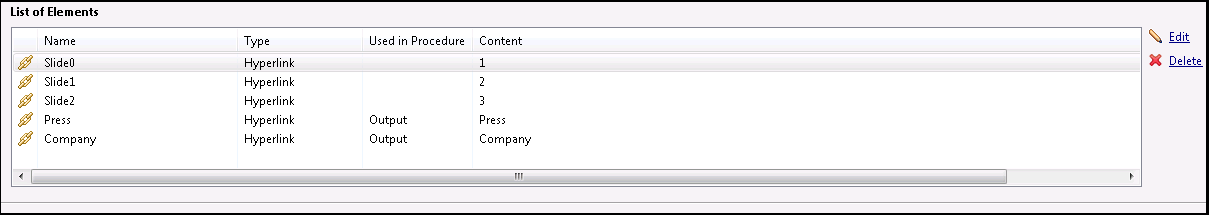
Reviewing the list of captured elements:
Once you have completed defining the captured element, the element will appear in the List of Elements table beneath the browser area. This list includes all the elements which have been selected on the page currently displayed. Captured elements are hihglighted in dark blue. When you select an element within the List of Elements table, the element will be highlighted in orange.
Repeat steps a-f to select and capture additional elements.
Either click on the relevant element within the Element List table and then click on Edit, or click on the element within the browser. The Edit Element dialog box is displayed and you are able to make the required changes.
Click on the relevant element within the Element List table and then click on Delete.
Click on the Selection Mode button.
Either enter the new address in the address field or click on the desired link.
To complete the recording and save the entity, click on the Finish button. The entity is opened for editing in the Editor area.
Refer to the Web Procedure Solution for further information.
The Web Procedure can be used to expose web services (Procedure Groups are required for this) or executed from within another procedure. To check that the procedure functions as expected, after you have completed recording the Web Procedure you can run the procedure from within the Designer.
To run the procedure, within the Editor, right-click on the relevant procedure and select . The execution flow is displayed in the Console and the main steps are written to the server log. Sometimes, the procedure requires entering values for input parameters. In such a case a pop-up appears.
For example:
<In>
<password></password>
<reconnect>true</reconnect>
<user>demo5</user>
</In>
When running the procedure for the first time, the values displayed within the tags are default values that were recorded when creating the Web Procedure. When running the procedure additional times, the last entered values are used.
Sometimes the procedure may fail to run. The Troubleshooting section may provide some useful tips.
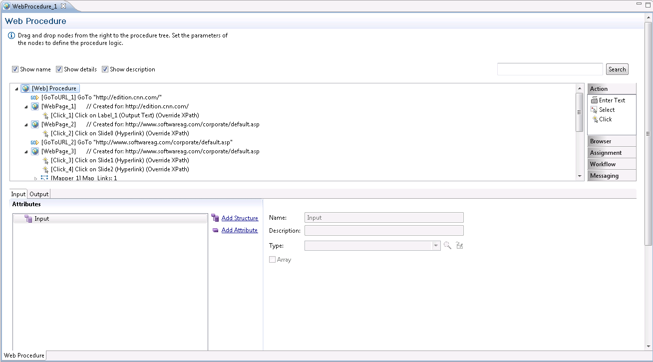
When completing the process of creating a new Web Procedure, it is opened in the Editor. As with other entities, it is possible to open the Web Procedure and edit it at a later stage. In the Editor you can refine the Web procedure, add logic, add, edit or delete elements and maintain the Web Page structure.
After the procedure is created, the original site may have changed and another page may have been added making your recording out of date. It is also possible that you simply want to add navigation to an additional URL. This can be done by adding a GOTO URL node to the procedure, and defining there the relevant URL. Refer to Working with Procedure Nodes and Web Procedure Nodes.
When recording the procedure, it is not possible to record a conditional scenario such as if a specific field has a specific value then the procedure should then navigate to a specific web page. Using the procedure nodes, actions and expressions to determine the condition, and then the GOTO URL navigation node to navigate to a different URL, you can add such logic into your procedure. Refer to Working with Procedure Nodes, General Procedure Nodes and Web Procedure Nodes.
You may find that you need to add an additional element to the Web Procedure. This can be for a number of reasons such as you may realize that you did not capture all the elements that you require or that the Web Page you originally recorded has changed and now you would like to add new elements that did not previously exist.
To add an element, select a Web Page node in the Procedure tree, and in the node details area, where the structure of the Web page and its elements are displayed, right click on the root node of the Web page and select Add Web Element. The Add Web Element dialog box is displayed.
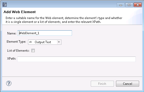
Enter a name for the element, select the relevant type and enter the XPath. Click Finish. The new element will be added to the Web Page schema and can then be used in child nodes.
A Web site which undergoes changes can cause the XPath of an element to change. As you would still like the Web procedure that you originally defined to be valid, you need to correct the XPath of the element to suit the new one:
Add a new element to the Web page.
In all the Mappers and actions, change the references to refer to the new element instead of to the old, outdated, element.
Delete the old element.
A Web element that is dependent on a user's action or input in runtime, requires an XPath that can change dynamically to suit this. In such cases, after recording the Web procedure and capturing the relevant element, change the XPath (in the procedure editor) by clicking on the Override option where this element is used (in one of the following Web Procedure Nodes: Enter Text action node, Select action node or Click action node) and defining the XPath using logic that will provide the required flexibility in runtime.
When mapping such an element as the output of the procedure, you may require using the Web Element Content expression.
It is possible to check whether an element exists within a specific web page using the Test Web Element Exists expression within the Web Page context.
To check whether a Web element exists:
Select Test Web Element Exists from the list of Boolean expressions.
Click Is/Is not to define the condition.
Click the XPath to open the Free Text dialog box and enter the XPath (you can copy-paste the XPath of an existing element by right-clicking an element and selecting Copy XPath to Clipboard).
As part of the Web procedure's logic, you may want to use or check the value of a certain element. This is done using the Web Element Content expression.
To retrieve the value of an element:
Select Web Helper>Web Element Content expression.
Select the XPath from which to retrieve the content.
Procedure inputs and outputs are defined when selecting the procedure root node. They may be used in any node of the procedure.
To define inputs and outputs
Within the Procedure root node of a procedure which you created, select the Input or Output tab as required.
Add attributes (Refer to Procedure Input and Output Attribute Types) and/or structures (Refer to Data Structures).
Nodes are used in Procedures and determine how the procedure will behave. Procedures consist of a number of nodes. These nodes are defined by the user to perform logical operations and are arranged in the order that these operations must be executed.
Note:
It is recommended to maximize the Editor screen when defining a
procedure.
The nodes in the procedure can display different information regarding the nodes by clicking on the different check boxes (Show name, Show details, Show description).
The Search field enables searching for a key word within the procedure nodes. The search mechanism is not case sensitive. The text is searched for within the description, details or name of the nodes. The nodes which contain the text will be selected and expanded in the tree, while other nodes will be collapsed.
An image of the Procedure tree can be saved as a PNG file, by right-clicking on the Procedure root node, and selecting .
To add a node
In the Procedure editor, select a node from the list of nodes.
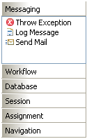
Drag and drop the node to the desired location within the procedure.
Edit the node.
To delete a node
Select the node within the Procedure.
Right-click on the node and select .
Moving a node within the Procedure
A node can be moved within a procedure by simply dragging and dropping it in the desired location.
To add/edit an expression
Expressions are used in procedure nodes. To edit an expression, right-click and select from the list.
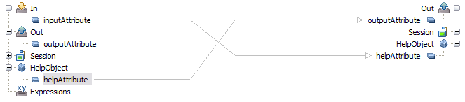
The Mapper tool enables mapping source elements to target output elements. The left-panel contains the entire source data elements that are available at the current flow scope depending on the node type (these element may also be expressions). The right-panel contains the potential target elements depending on the flow scope and the node type. Using the drag-and-drop operation, it is possible to define that when the Mapper is executed, the value/s in the source element will be copied to the target element. These definitions are indicated by lines, linking between the source element and the target element, and also are listed under the relevant node in the procedure nodes tree.
Note:
When mapping a source element (e.g inputAttribute in the screen shot
below) to a target element (e.g helpAttribute), and in the same mapper mapping
the same element (helpAttribute) to another target element (outputAttribute),
as the mapper does not enable defining the order in which the elements will be
mapped, this can cause a conflict. Therefore it is recommended to perform such
a mapping using two separate mappers.
The procedure nodes that enable using the Mapper tool:
Create Mappings
Group Arrays (the target will include objects relevant to the specific Group Array node)
Execute Procedure (lists only the inputs relevant to the specific procedure)
Flow Procedure nodes:
Create Emulation Session (lists only the inputs relevant to the specific procedure)
Create DbSession (lists only the inputs relevant to the specific procedure)
DbSelect (lists the dynamic inputs. Refer to Creating a dbSelect node)
DbExecute- relevant for Flow Procedures only.
RollBack (lists only the inputs relevant to the specific procedure)
Commit (lists only the inputs relevant to the specific procedure)
Create RPC Session- relevant to Flow Procedures only.
End Session (lists only the inputs relevant to the specific procedure)
Path nodes:
Step (input to source screen\screen group, output from target screen\screen group)
Path (lists only the inputs relevant to the specific path)
Screen Mapper
The expressions that enable using the Mapper tool:
Free Text (using tokens)
Execute Procedure
Host Keys (using tokens)
There are a number of different types of source and target elements that can be mapped:
Mapping a Structure Type Element to a Structure Type Element
Mapping a Number of Simple Elements to a Structure Type Element
Drag the element in the source frame of the mapper to the relevant element in the target frame. When the Mapping is executed, the source element will be copied to the target element.
When mapping an array to an array, it is possible to copy all the source data in an array element to the target element, or it is possible to copy only some of the data to a certain place in the target array.
To copy an array element to an array element
Drag the element in the source frame of the mapper to the relevant element in the target frame. When the Mapper is executed, the source element will be copied to the target element. A line will be displayed between the two, indicating that the value from the source element will be placed in the target element.
By default, the data is appended to the existing data. This is indicated by a + sign which appears on the line connecting between the source element to the target element. If the + sign does not appear, double-click on the middle area of the mapper (between the area of the source data and the area of the target data) to display the Link Properties dialog box. Select the Append check box and click OK.
To copy an array element or part of an array element using an
index
To define that all or some of the source array values will be placed in a particular place in the target array, drag a line from the element in the source frame of the mapper to the element in the target frame. A line will be displayed between the two, indicating that the value from the source element will be placed in the target element.
Right-click on the middle area of the line to display the Link Properties dialog box.
To overwrite existing data, ensure that the Append check box is not selected.
To copy the data which is from a certain index in the array, right-click and define the Source Index.
To determine that the data will be placed in the middle of the array starting from a certain index, right-click and define the Target Index.
When you do not need the entire source array but only a specific number of values, define the number of values in the Count field.
Click OK to close the dialog box.
Caution:
Ensure, that in the Link Properties dialog box, either the Append
check box is selected or the Source or/and Target Index have values, otherwise
the procedure may not function as you intended and may also cause performance
problems.
The simple element can be added to the array in two ways: by appending the value to the existing array or by placing the value in a specific place in the array.
To append a simple type element to an array
Drag the element in the source frame of the mapper to the relevant element in the target frame. When the Mapper is executed, the source element will be copied to the target element. A line will be displayed between the two, indicating that the value from the source element will be placed in the target element.
Right-click on the middle area of the mapper (between the area of the source data and the area of the target data) to display the Link Properties dialog box. In the Target Index field right-click on <exp> to set the index value where the element will be placed.
Click OK to close the dialog box.
Caution:
Ensure that if you remove the select from the Append check box,
you define the Target Index, otherwise the value of the simple type element
will be placed in the [0] index.
To map a value from an array type element to a simple type element, it is necessary to define the index of the relevant value in the array. If you do not define this index, the [0] index will be used.
To place an array type element value in a simple type element
Drag the element in the source frame of the mapper to the relevant element in the target frame. When the Mapper is executed, the source element will be copied to the target element. A line will be displayed between the two, indicating that the value from the source element will be placed in the target element.
Right-click on the middle area of the mapper (between the area of the source data and the area of the target data) to display the Link Properties dialog box. In the Source Index field right-click on <exp> to set a value for the index.
Click OK to close the dialog box.
The process of mapping the attributes of a structured element to the attributes of a structured element is similar to mapping simple and array elements (refer to Mapping Source Elements to Target Elements). When mapping an element in a structured element to an element in a structured element, map the relevant internal elements and do not map the structured root element.
Caution:
Mapping the structure root to the structure root will only map
elements of the source structure to the elements of the target structure it
they have the same name. Always verify that the correct links are made when
mapping different types of structures.
It is possible to map a number of simple elements to a structure.
To map a number of simple elements to a data structure type
element
Select more than one simple element in the source frame of the mapper using CTRL or SHIFT. Drag the selected elements to the relevant data structure in the target frame. When the Mapper is executed, the source element will be copied to the target element within the data structure. A line will be displayed between the two, indicating that the value from the source element will be placed in the target element.
To understand the Program feature in ApplinX, we first need to overview the concept of Remote Procedure Call (RPC). RPC is a description for APIs that permit distributed applications to interact with each other across the network. As part of its host integration capabilities, the ApplinX server implements RPC calls to execute host programs and routines, thus adding another type of interaction with hosts in addition to screens and screen data.
This Wizard guides you through a sequence of instructions to import a program object and corresponding field elements. Currently, the Wizard supports the import of program objects for COBOL and RPG programs for AS/400 hosts.
To create a new Program Procedure
Select the relevant application or the Root node of the application.
In the ApplinX Explorer tool bar, click on the arrow to the right of the icon and select . The New Program Procedure wizard is displayed.
Enter a name and description (optional) and click .
The Import Specifications screen is displayed.
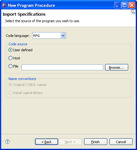
From the Code language drop-down list select COBOL or RPG.
Specify the code source:
User defined: Enables you to define a new program.
Host: Enables you to import a program from a host.
File: Enables you to import a program from a file. Specify the code source file.
For more convenient use, ApplinX can rename the parameters automatically for you. Advanced users (AS/400 hosts only): When RPG is selected, ApplinX can retrieve the Program's source file directly from the AS/400 machine. Click the Code retriever settings button to display the Program - Advanced dialog. Specify the Host Library, File, Member and Line Length (default is 100). Enter the host's address or select a previously defined host from the drop-down list. Enter the Host's User name and Password, otherwise the default values as set in the host configuration are used. Click . Click
Defining Program Procedure Inputs and Outputs
Double-click on the relevant Program Procedure from within the Repository. The Editor area displays the Procedure Program. Add/edit parameters. Refer to the parameter details.
The External Web Service feature enables creating procedures based on a WSDL which describes a Web service within the organization. An External Web Service Procedure can be invoked, either by Flow, Path or Web Procedures.
Refer to External Web Services Referencesection.
Note:
This feature is only available when working with a SOA
license.
Current limitations:
ApplinX supports only DOC/Literal (wrapped and bare) WSDLs.
ApplinX supports the following XSD types (refer to http://www.w3.org/2001/XMLSchema) and any ComplexType which uses them:
String
Boolean
Double
Float
Int
Integer
Long
Date (The format can only be 2001-07-04T12:08:56.235.
dateTime
External Web Services currently do not support the following services:
Services that contain Web methods that use data types comprised of ANY tags.
For example:
<s:element minOccurs="0" maxOccurs="1"
  name="GetHolidaysForMonthResult">
           <s:complexType>
		           <s:sequence>
               <s:element ref="s:schema" />
               <s:any />
		           </s:sequence>
           </s:complexType>
          </s:element>
Services that contain Web methods that use data types comprised of complex data types defined within the parent data type definition.
For example:
<s:element name="GetHolidaysForDateRangeResponse">
     <s:complexType>
		      <s:sequence>
          <s:element minOccurs="0" maxOccurs="1"
		         name="GetHolidaysForDateRangeResult">
            <s:complexType>
		            <s:sequence>
<s:element minOccurs="1" maxOccurs="1" name="year"	type="s:int" />
              </s:sequence>
            </s:complexType>
		         </s:element>
          </s:sequence>
        </s:complexType>
		    </s:element>
Creating an External Web Service
Select the relevant application.
In the menu select . If you have the CentraSite plug-in, but have not configured the CentraSite connection, the Eclipse Preferences dialog box is displayed requiring you to configure the connection. This is not required when you want to use a WSDL URL.
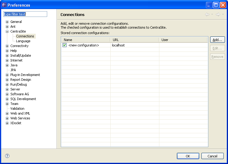
If you wish to use a Web Service that is registered in CentraSite, ensure that you have set a connection configuration in the Eclipse Properties dialog box and that you supplied a valid user name and password (these will be used when attempting to retrieve the WSDL file from CentraSite). It is recommended to test the connection to CentraSite (Test button), after configuring the connection.
The External Web Service wizard is displayed.
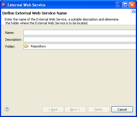
Enter a name and click Next.
The Web Service Source screen is displayed.
Select whether to use a WSDL URL (if you don't have CentraSite or if the Web Service is not registered in CentraSite) or CentraSite.
When relevant, enter the WSDL URL or select a file name.
When selecting CentraSite, you will be required to enter the user name and password to be used when retrieving the WSDL from CentraSite (the default values are taken from the CentraSite preferences). Then, select one of the web services (in the Result section). Refer to the CentraSite documentation on Empower for further information regarding this dialog box.
When entering a WSDL URL, you may be required to provide a user name and password.
Click . The External Web Service is displayed in the Editor area. The General tab displays the basic information about the web service and the Structure tab displays the contents of the Web service.
Note:
It is possible to change the target server. This can typically be
used when changing the environment, such as from developing and testing
environment to the production environment (which may be on a different server
than the developing and testing server), as when changing the environment, the
URL will be broken, causing the External Web Services not to work. This is done
by clicking on the relevant button in the General tab and then selecting the
new address (IPv4 and IPv6 address formats are supported) and port. When
necessary, you can also select to update the WSDL URL accordingly. These
changes can be applied just to the current Web Service, or to all External Web
Services using the same target server (when selecting this option, the list of
updated services appears in the server log).
After creating a procedure, use the ApplinX Debugger tool to observe the run-time behavior of your procedure and determine the location of logical errors. With the debugger, you can control the execution of your program by setting breakpoints, stepping through your code, running the code to the cursor position and examining the contents of variables. Refer to the Eclipse help for further details on the Debugger.
Debugging procedures are based on the given capabilities of the Eclipse based debug tools. You can debug "step-by-step", using the "step-over" action (F6). You can achieve "Run to Cursor" by setting the breakpoints in the proper place and using the "run/resume" action (F8).
To debug a procedure
Right-click on the relevant procedure and select Debug or Run.
Note:
The first time a Path Procedure that uses a Connection Pool is
debugged, the Session Selection dialog box is displayed, requiring you to
select the relevant session to use when debugging this Path Procedure.
Sometimes, the procedure requires entering values for input parameters. In such a case a pop-up appears. For example:
<In>
<password></password>
<reconnect>true</reconnect>
<user>demo5</user>
</In>
The values displayed within the tags are default values set by the user.
When deleting a text value and/or not entering a value (e.g.
<password></password>), an empty string is used.
When deleting a boolean, numeric or date value and/or not entering a value, the ApplinX default is used (ApplinX default values are as follows: for a boolean parameter - false, numeric - 0 and date - current date).
When removing a whole element (such as deleting
<reconnect>true</reconnect>), the user defined default
is used when one exists, otherwise, the ApplinX default is used (ApplinX
default values are as follows: for string parameters - null, boolean - false,
numeric - 0 and date - current date).