Deployment Configuration: Fully Redundant
Deployment Configuration: Fully Redundant
Description
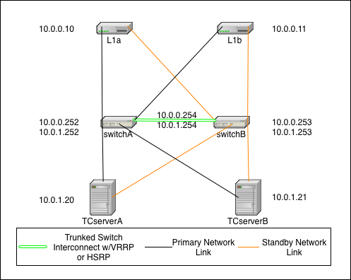
This is the fully redundant network configuration. It relies on the failover capabilities of Terracotta, the switches, and the operating system. In this scenario it is even possible to sustain certain double failures and still maintain a fully functioning cluster.
In this diagram, the IP addressing scheme is merely to demonstrate that the L1s (L1a & L1b) can be on a different subnet than the L2s (TCserverA & TCserverB). The actual addressing scheme will be specific to your environment. If you choose to implement with a single subnet, then there will be no need for VRRP/HSRP but you will still need to configure a single VLAN (can be VLAN 1) for all TC cluster machines.
In this diagram, there are two switches that are connected with trunked links for redundancy and which implement Virtual Router Redundancy Protocol (VRRP) or HSRP to provide redundant network paths to the cluster servers in the event of a switch failure. Additionally, all servers are configured with both a primary and secondary network link which is controlled by the operating system. In the event of a NIC or link failure on any single link, the operating system should fail over to the backup link without disturbing (e.g. restarting) the Java processes (L1 or L2) on the systems.
The Terracotta fail over is identical to that in the simple case above, however both NIC cards on a single host would need to fail in this scenario before the TC software initiates any fail over of its own.
Additional configuration

Switch - Switches need to implement VRRP or HSRP to provide redundant gateways for each subnet. Switches also need to have a trunked connection of two or more lines in order to prevent any single link failure from splitting the virtual router in two.
Operating System - Hosts need to be configured with bonded network interfaces connected to the two different switches. For Linux, choose mode 1. More information about Linux channel bonding can be found in the Linux Bonding Driver description at
http://www.linuxfoundation.org/collaborate/workgroups/networking/bonding. Pay special attention to the amount of time it takes for your VRRP or HSRP implementation to reconverge after a recovery. You don't want your NICs to change to a switch that is not ready to pass traffic. This should be tunable in your bonding configuration.
Test Plan - Network Failures Redundant Network
The following tests continue the tests listed in Network Failures (Pt. 1). Use these tests to confirm that your network is configured properly.
TestID | Failure | Expected Outcome |
FS8 | Loss of any primary network link | Failover to standby link |
FS9 | Loss of all primary links | All nodes fail to their secondary link |
FS10 | Loss of any switch | Remaining switch assumes VRRP address and switches fail over NICs if necessary |
FS11 | Loss of any L1 (both links or system) | Cluster continues as normal using only other L1 |
FS12 | Loss of Active L2 | mirror L2 becomes the new Active L2, All L1s fail over to the new Active L2 |
FS13 | Loss of mirror L2 | Cluster continues as normal without TC redundancy |
FS14 | Loss of both switches | non-functioning cluster |
FS15 | Loss of single link in switch trunk | Cluster continues as normal without trunk redundancy |
FS16 | Loss of both trunk links | possible non-functioning cluster depending on VRRP or HSRP implementation |
FS17 | Loss of both L1s | non-functioning cluster |
FS18 | Loss of both L2s | non-functioning cluster |
Test Plan - Network Testing Redundant Network
After the network has been configured, you can test your configuration with simple ping tests and various failure scenarios.
The test plan for Network Testing consists of the following tests:
TestID | Host | Action | Expected Outcome |
NT4 | any | ping every other host | successful ping |
NT5 | any | pull primary link during continuous ping to any other host | failover to secondary link, no noticeable network interruption |
NT6 | any | pull standby link during continuous ping to any other host | no effect |
NT7 | Active L2 | pull both network links | mirror L2 becomes Active, L1s fail over to new Active L2 |
NT8 | Mirror L2 | pull both network links | no effect |
NT9 | switchA | reload | nodes detect link down and fail to standby link, brief network outage if VRRP transition occurs |
NT10 | switchB | reload | brief network outage if VRRP transition occurs |
NT11 | switch | pull single trunk link | no effect |