Creating tree controls
The input of tabular data determines the content of the tree control, as well as the appearance of each object in the tree. As with other controls, to configure a drill-down, set substitutions, or run a command when a user clicks a tree node, use the actionCommand property. As with other table-driven objects, the drillDownColumnSubs property can be configured to set substitutions to column values from the row in the table (attached to the valueTable property) that corresponds to the selected tree node.
After you attach your tabular data to the tree control valueTable property, specify the table format for the tree in the valueTableFormat property. The table format is determined by the format of the table you attach to the valueTable property. There are two table format options, each with their own requirements:

Row-leaf: This format is intended for use when the
valueTable property is attached to a table and all leaves in the tree are at the same depth. For example, where the tree control is attached to an instance table. The
nodeIndexColumnNames property specifies the columns from the instance table that will appear in the hierarchy in the tree control.
Row-node: If the row-leaf format is not suitable for your data, use the row-node format. Your data table must also contain a row for each node in the tree, including the top-level node (rather than just the leaf nodes, as with the row-leaf format), as well as a column for the node and a column for the parent node. The row-node format allows each leaf of the tree to have a different depth.
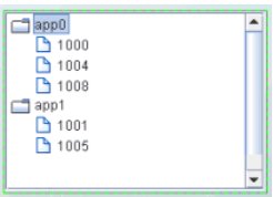
The default table format is row-leaf. The following are examples of the row-leaf and row-node table formats, which both produce the tree in the image that follows. Here is a row-leaf table:
App Name | PID |
App0 | 1000 |
App0 | 1004 |
App0 | 1008 |
App1 | 1001 |
App1 | 1005 |
Here is a row-node table:
Node | Parent |
app0 | |
1000 | app0 |
1004 | app0 |
1008 | app0 |
app1 | |
1001 | app1 |
1005 | app1 |
Here is the tree control that both these tables produce:
After you configure the tree table format, you can optionally configure the tree control icons. See
Configuring tree control icons.
Creating row-leaf format control trees
In the row-leaf table format, there is one row in the table for each leaf node in the tree. A leaf node is added to the tree for each row in the table attached to the valueTable property. The path to a leaf node (that is, the ancestor nodes of the leaf) is determined by the values in each of the table columns specified by the nodeIndexColumnNames property. When the valueTable property is attached to the instance table, the tree's nodeIndexColumnNames property is typically set to the same columns that are specified in the Display variables field of the Attach to Apama dialog.
To illustrate how to create a tree using the row-leaf format, consider a table that has two columns, App Name and PID, and the following rows:
App Name | PID |
app0 | 1000 |
app0 | 1004 |
app0 | 1008 |
app1 | 1001 |
app1 | 1005 |
Set tree control properties as follows:
Attach the tree control object's
valueTable property to Apama as you would attach any table object. In the
Attach to Apama dialog, in the
DisplayVariables field, select the variables
App Name and
PID.
Set the
valueTableFormat property to the
Row-Leaf format.
Set the
nodeIndexColumnNames property to
App Name;PID.
The following image illustrates the structure of the tree. There are two nodes labeled app0 and app1. Node app0 has three child nodes labeled 1000, 1004, 1008. Node app1 has two child nodes, labeled 1001 and 1005.
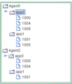
Suppose we add another column, AgentName, by selecting that variable from the Display Variables field of the Attach to Apama dialog. The table has the following rows:
AgentName | App Name | PID |
Agent1 | App0 | 1000 |
Agent1 | App0 | 1004 |
Agent1 | App0 | 1008 |
Agent1 | App1 | 1001 |
Agent1 | App1 | 1005 |
Agent2 | App0 | 1000 |
Agent2 | App0 | 1004 |
Agent2 | App1 | 1001 |
We also update the tree control nodeIndexColumnNames property to AgentName;App Name;PID.
The following figure illustrates the new structure of the tree. The tree now has two top-level nodes labeled Agent1 and Agent2, each with two child nodes, app0 and app1.
As illustrated above, the label string for a node at depth N is taken from the Nth column in the nodeIndexColumnNames property. Therefore, the labels for the top-level nodes come from the first column in the nodeIndexColumnNames property (AgentName), the labels for the second-level nodes come from the second column in nodeIndexColumnNames property (App Name), and so forth.
To specify node labels from a different set of valueTable columns, use the nodeLabelColumnNames property. Enter a semicolon-separated list of column names in the nodeLabelColumnNames property, one for each level in the tree, where the Nth column name in the list contains the labels for tree nodes at depth N.
To modify tree control icons or configure tree control icon behavior, see
Configuring tree control icons.
Creating row-node format tree controls
In the row-node format tree control, there is one row in the table for each node in the tree, including the top-level node rather than just one row for each of the leaf nodes as with the row-leaf format.
There are two columns in the table that help define the tree structure:
One of the table columns contains a node ID string and is identified by the
nodeIdColumnName property. By default, the node ID string is used as the node label in the tree. The node ID string must be unique among all nodes with the same parent. Or, if the
uniqueNodeIdFlag property is checked, each node ID string must be unique in the entire tree.
Another table column contains the ID of the parent node, which is identified by the
parentIdColumnName property.
To create the same tree as the row-leaf format example in the previous topic, a table representation of the tree control using the row-node format would be as follows:
Node | Parent |
app0 | <blank> |
1000 | app0 |
1004 | app0 |
1008 | app0 |
app1 | <blank> |
1001 | app1 |
1005 | app1 |
The <blank> entries represent an empty string, which indicates that nodes app0 and app1 have no parent, making them top-level nodes in the tree.
Set the tree control properties as follows:
valueTable property to attach to the table that contains the data to be displayed
valueTableFormat property to the
Row-Node format
nodeIdColumnName property to
Node parentIdColumnName property to
Parent The result is a tree structure with two top-level nodes labeled app0 and app1. Node app0 has three child nodes labeled 1000, 1004, 1008. Node app1 has two child nodes, labeled 1001 and 1005.
To add another tree level for the AgentName, as in the Row-Leaf format example in the previous topic, modify the table as follows:
Node | Parent |
Agent1 | <blank> |
app0 | Agent1 |
1000 | app0 |
1004 | app0 |
1008 | app0 |
Agent2 | <blank> |
app0 | Agent2 |
1000 | app0 |
1004 | app0 |
app1 | Agent2 |
1001 | app1 |
1005 | app1 |
Also, uncheck the uniqueNodeIdFlag property to allow for node IDs that are not unique, such as the app0 and 1000 nodes in the example, which are used in multiple tree levels. Because some of the rows are also identical, the order of the table rows is important. For example, this row appears twice in the table: 1000 app0. In each case the 1000 app0 row comes after a unique parent row: first under app0 Agent1 and then under app0 Agent2. The tree uses this information to determine where to place the node for 1000 in each case.
The tree now has two top-level nodes labeled Agent1 and Agent2, each with two child nodes, app0 and app1.
By default, the node ID string is used as the node label in the tree. If a different column in the table must provide the label, specify the name of that column in the nodeLabelColumnName property.
In the row-node format, each branch of the tree can have a different depth, while in the row-leaf format all branches typically have the same depth, which is the number of columns specified in the nodeIndexColumnNames property.
To modify tree control icons or configure tree control icon behavior, see
Configuring tree control icons.