A screen group binds several screens that share common visual or logical attributes. The relationship between screen groups to screens is many-to-many: a screen group can include many screens, and a screen may be included in many groups. This document covers the following topics:
See also Screens and Screen Groups in the Natural Screen Tester Reference Guide.
A screen that belongs to a group inherits all the field mappings that are mapped to the group. Unidentified screens are associated with screen groups based on the screen group identifiers defined. Identified screens relate to specific, predefined screen groups (specified in the Screen entity dialog box), ignoring the screen group identifiers. In addition, it is possible to define a screen group that includes all the unidentified screens.
Screen groups are typically used:
To identify a large number of Host Screens without having to identify all the relevant Natural Screen Tester screens.
To define once a Field Mapping that is repeated in multiple screens (error message, screen title, command line, menu selection, etc.).
To implement Screen Creation Definitions
Note that when there are a number of screen groups, it is necessary to determine the order of priority between the screen groups. For more details refer to Prioritizing Screen Groups
When using Screen Groups, you may want to associate to a specific Screen Group all the screens which contain a certain field, wherever this field may appear on the screen. For example, you may want all screens which contain a menu selection field to belong to the same screen group. This is possible using the mapping type called "Single Dynamic". This mapping type maps fields according to their leading label, no matter where this field appears on the screen.
Fields can be mapped according to their position in the screen or according to their leading label:
The Screen Group entity binds several Screens that share common visual or logical attributes. Each screen group must have unique name. A screen group may have identifiers enabling the screen group to be implicitly associated to specific unidentified screens or have no identifiers, enabling the screen group to be associated with all unidentified screens. This section covers the following topics:
![]() To create a new Screen Group
To create a new Screen Group
Select the relevant application.
In the menu select . The New Screen Group wizard is displayed.
Enter a name for the Screen Group, a suitable description and determine the folder where the screen is to be located. Click . You have now created a Screen Group entity in the repository.
For the Natural Screen Tester Server to recognize a host screen, you need to identify the screen in Natural Screen Tester. The screen is identified using "identifiers". Different identifier types include identifying specific text on the screen, the screen cursor position or the field attributes. The Natural Screen Tester Server analyzes the current screen and tries to match it to all of the screen identification strings stored in the repository. For a screen to be recognized, all its identifiers must be matched. You may define an unlimited number of identifiers. The following identifiers are available:
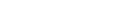
Use text identifiers to identify a screen by selecting specific text that appears on the screen. Use the Capture from Screen feature to identify a string of text accurately from the host screen and insert this string into the text box.
![]() To define a text identifier
To define a text identifier
Access the relevant screen.
Select the Identifiers Tab.
Determine whether to ignore the window definitions during the identification of a screen, select the relevant check box. Once the screen is identified the full screen is used.
Click the arrow on Add Identifier and select . Another row will be added to the list of identifiers.
Select Is (default) in order to match the exact text on the host screen. Alternatively, select Is NOT if any text other than the specified is suitable as a screen identifier. Check Empty to identify an empty space on the host screen. This clears the Text text box.
Select Rectangle to indicate that the identifier should be searched for within the defined rectangle, Position, to indicate that the identifier must start at a specific position or Anywhere on screen to indicate that the identifier may be anywhere on the screen.
When selecting Rectangle, define the rectangle range (start and end row and column.). When selecting Position, select the row and column.
It is also possible to add an identifier by selecting the area in the host screen, and then clicking Add Identifier. When selecting an area which is a rectangle, identifiers will be added for each and every row of the selected rectangle.
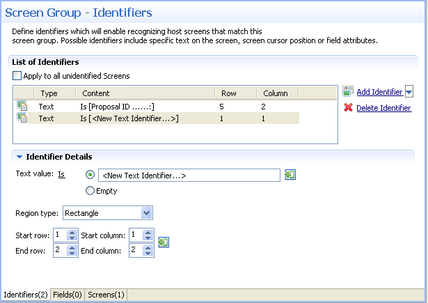
Use the cursor position identifier to identify a screen by the cursor position when the screen is loaded.
![]() To define a cursor position identifier
To define a cursor position identifier
Access the relevant screen.
Select the Identifiers Tab.
To ignore the window definitions during the identification of a screen, select the relevant check box. Once the screen is identified the full screen is used.
Click the arrow on Add Identifier and select . Another row will be added to the list of identifiers.
Select Is to indicate that the cursor is positioned within the region area details that follow. Alternatively, select Is NOT to indicate that the cursor is not positioned within the region area details that follow.
Select Rectangle to indicate that the cursor position should be searched for within the defined rectangle or Position, to indicate that the cursor position must start at a specific position
It is also possible to add an identifier by selecting the area in the host screen, and then clicking Add Identifier.
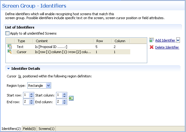
Use the Attribute identifier to identify a screen by the host's attributes. Attributes of the host screen may be Protected, Intensified or Hidden.
![]() To define an attribute identifier
To define an attribute identifier
Access the relevant screen.
Select the Identifiers Tab.
To ignore the window definitions during the identification of a screen, select the relevant check box. Once the screen is identified the full screen is used.
Click the arrow on Add Identifier and select . Another row will be added to the list of identifiers.
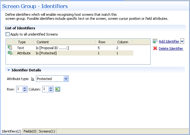
Select whether the Attribute Type is/is not Protected, Hidden, Intensified or Reversed video.
Enter values or use the Capture from Screen feature to indicate a specific location of the attribute by its Row and Column.
It is also possible to add an identifier by selecting the area in the host screen, and then clicking Add Identifier.
Use the Window identifier to identify a screen by determining whether it is or is not a window. In Natural UNIX, it is possible to identify a screen by determining whether it is a window and whether it has specific text in the title.
![]() To define a window identifier
To define a window identifier
Access the relevant screen.
Select the Identifiers Tab.
To ignore the window definitions during the identification of a screen, select the relevant check box. Once the screen is identified the full screen is used.
Click the arrow on Add Identifier and select . Another row will be added to the list of identifiers.
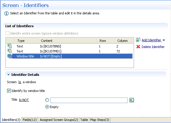
Select Is to indicate that the screen is a window. Alternatively, select Is NOT to indicate that the screen is not a window.
For Natural UNIX hosts: Select the check box to indicate to identify by the window title. You can enter text for the title or select the text in the session view and click the Capture from screen icon. You can also identify a screen which is a window and does not have a title by selecting the Empty radio button.
When a screen is identified, field entities can be mapped to it. A field makes relating to a string on the host screen much simpler. Fields offer an enhanced way of referring to host fields - by their name rather than by their position. In addition, mapped fields simplify future maintenance - when a field changes in the original host application, updates only need to be made to the field definition. The following guidelines will help you determine which fields to identify:
Fields that will be referenced in code (when binding Web page controls to host fields by name).
Fields that will be part of navigation paths.
Fields that will be used as test case input and output attributes to expose host transactions as assertions.
Recommended: all input and output fields (not constants).
Any field in the host application you would want to expose as an assertion.
An application field makes relating to a string on the host screen much simpler. Fields offer an enhanced way of referencing host fields - by their name rather than by their position. Using fields has many advantages:
A field's ID is meaningful regarding the contents of the field, unlike a numeric position.
You define a field only once, and later can reference that definition in all of your code - knowing you always mean the same definition.
If changes in the host application occur in the future, the only place that requires to be changed is the field definition.
Field properties can be accessed by right-clicking on the Repository node and selecting and then searching for the specific field.
In the Field Editor, it is possible to set the Input Mask (Defines the values that can be entered in the field) and the field type (numeric or alphanumeric).
An input mask consists of literal characters along with special characters that together determine the value that may be entered into input fields. When a user defines a mask on an input field, client side validation will be carried out on the input format. Common usage is in date/time and number or currency fields.
![]() To implement this feature you must change the web application
configuration in the configuration editor
To implement this feature you must change the web application
configuration in the configuration editor
Open a new browser and run your Web application.
Click on the Configuration link. The Configuration Editor will be displayed.
In the Instant node select the Reflect emulation behavior check box.
The following table shows some useful input mask definitions and examples of values you can enter. Refer to Valid input Characters for details on the codes used to create input mask definitions.
| Input Mask Definition | Example Values |
|---|---|
| (000) 000-0000 | (206) 555-0248 |
| (999) 999-9999 |
(206) 555-0248 ( ) 555-0248 |
| (000) AAA-AAAA | (206) 555-TELE |
| #999 |
-20 2000 |
| >L????L?000L0 |
GREENGR339M3 MAY R 452B7 |
| 00000-9999 |
98115- 98115-3007 |
| L?????????????? |
Maria pierre |
| ISBN 0-&&&&&&&&&-0 |
ISBN 1-55615-507-7 ISBN 0-13-964262-5 |
Natural Screen Tester interprets characters in the Input Mask property definition as shown in the following table. To define a literal character, enter any character other than those shown in the table, including spaces and symbols. To define one of the following characters as a literal character, precede that character with a "\".
| Character | Description |
|---|---|
| 0 | Digit (0 through 9, entry required; plus [+] and minus [-] signs not allowed). |
| 9 | Digit or space (entry not required; plus and minus signs not allowed). |
| # | Digit or space (entry not required; blank positions converted to spaces, plus and minus signs allowed). |
| L | Letter (alphabetic, entry required). |
| ? | Letter (alphabetic, entry optional). |
| A | Letter or digit (entry required). |
| a | Letter or digit (entry required). |
| & | Any character or a space (entry required). |
| C | Any character or a space (entry optional). |
| \ | Causes the character that follows to be displayed as a literal character. Frequently displayed any of the characters listed in this table as literal characters (for example, \A is displayed as just A). |
When a screen is identified, field entities can be mapped to it. A field makes relating to a string on the host screen much simpler. Fields offer an enhanced way of referring to host fields - by their name rather than by their position. In addition, mapped fields simplify future maintenance - when a field changes in the original host application, updates only need to be made to the field definition. The following guidelines will help you determine which fields to identify:
Fields that will be referenced in code (when binding Web page controls to host fields by name).
Fields that will be part of test cases.
Fields that will be used as test case input and output attributes as assertions.
Fields that will be used within tables.
Recommended: all input and output fields (not constants).
Any important field in the host application.
There are limitations when defining a mapping. A mapping cannot:
Start in an unprotected field and end in a protected field, or vice versa.
Start with an attribute byte.
Overlap another mapping on the same screen.
Start in one line and end on another line.
Start on one line and end off the screen's limits.
![]() To map fields according to their position in the screen
To map fields according to their position in the screen
Click the Fields tab to view and/or modify the fields in this screen group.
Click the arrow next to , and select or icon to add a new field mapping.
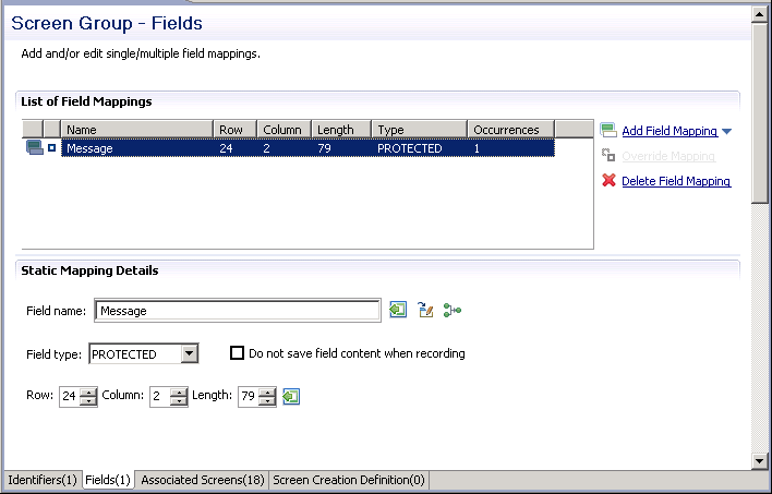
In the Field name field, either enter a field name or enter the first letters of a field name and then click CTRL and SPACE to display relevant fields.
Select the Protection type: Protected (cannot be edited in host), Unprotected (editable in host) or Both (may sometimes be editable and sometimes not).
The Do not save field content when recording check box enables not saving data which you do not want to be displayed when viewing the recorded trace file.
The Row and Column fields indicate the position of the field on the screen. The values of these fields can be changed using the Capture from Screen feature or by entering values in the fields.
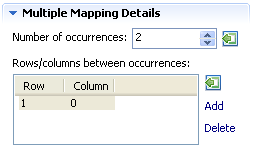
When adding a multiple field mapping, determine the number of occurrences and the rows and/or columns between occurrences.
To delete a field mapping, click on the Delete Field Mapping hyperlink.
Note:
This feature is not available in right to left and character mode applications.
![]() To map fields according to their leading label
To map fields according to their leading label
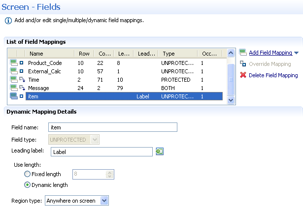
In some screens, the position of a field may vary. It is therefore necessary to map some fields in such a way, that even if they appear in a different position, they will still be recognized and mapped. This is possible by defining the label near the field (the label must be to the left of the field) and identifying the field according to this label. This mapping type is called "Single Dynamic" as the mapping position changes dynamically according to the leading label. Use this type of mapping only when the screens in the screen group have a very similar structure. Refer to Dynamic Field Mapping Limitations.
Click the Fields tab to view and/or modify the fields in this screen.
Click the arrow next to New Mapping, and select to add a new field mapping.
In the Field name field, either enter a field name or enter the first letters of a field name and then click CTRL and SPACE to display relevant fields.
Select the field protection type: Unprotected, Protected or Both. Prefer to set the field type either as Protected or Unprotected when you are sure of the type of the dynamic field. Use Both when you are not sure of the type of the dynamic field.
Determine the leading label: the leading label is the label which appears before the field. This label is inserted as the Field name and can be edited. The label you define should be as accurate as possible (do not use strings which normally appear within the field).
Determine the method to use to search for the label:
Contains text: Searches for the given text anyway in the defined region (default).
Exact phrase: Searches for the given text within the defined region. The text must be preceded and followed by at least two white space characters.
Contains word: Searches for the given text as word(s) within the defined region.
Regular expression: Searches for the given pattern within the defined region. Refer to Regular Expression Syntax.
Note:
When selecting a different option, after defining a regular
expression search definition, the value of the previous regular expression
definition will be lost.
Define the region type in which the label will be searched for: anywhere in the screen, within a specified rectangle or within a specified row range. The Row and Column fields indicate the position of the label on the screen. The values of these fields can be changed using the Capture from Screen feature or by entering values in the fields.
Use length:
In Unprotected fields: Determine whether to recognize a field mapping according to the leading label and the length of the input field (Fixed length) or just according to the leading label (Dynamic length).
In Protected fields: The length defined here is the length of the mapping. The identified field is cropped to the specified length.
Define the region type in which the field will be searched for: anywhere in the screen, within a specified rectangle or within a specified row range. The Row and Column fields indicate the position of the field on the screen. The values of these fields can be changed using the Capture from Screen feature or by entering values in the fields.
Note:
The region will be displayed in the Session View with a yellow
frame, and the background of the screen within this region will be
dotted.
The following guidelines apply when mapping fields according to their leading labels:
It is preferable to define your regions as rectangles, that do not overlap each other, and whose size are minimal.
The feature is best suited to locate dynamic fields which change their location vertically so that labels are aligned vertically in one region, and fields aligned vertically on a region to the right of the labels.
A screen that belongs to a group inherits all the field mappings that are mapped to the group.
![]() To associate screens to a screen group
To associate screens to a screen group
Access the relevant screen and click on the Associated Screens tab. The list of Screen Groups currently associated with this screen are listed.
Click on Assign Screens to select additional screens to be associated with this screen group.
Screen Creation Definitions are a set of basic definitions which are used to create a new Natural Screen Tester screen. These definitions include the default screen name, initial identifiers and determine whether input fields will be created. Creating a new screen using screen creation definitions reduces the complexity and the time required to identify new screens.
To use this feature, at least one set of Screen Creation Definitions must be created within a Screen Group (in the dedicated tab). When navigating within a session, and reaching an unidentified screen, Natural Screen Tester searches for Screen Groups which match the unidentified screens, and then creates a new screen based on the screen group's identifiers and on parameters defined in the creation definition configured in the Screen Group. This process can be initiated in three different modes: automatic, semi-automatic and manual (defined in the view session). Refer to Changing the Screen Definition Mode.
![]() To create screen creation definitions
To create screen creation definitions
In the Screen Creation Definition tab, click on Create Definition to define a new screen creation definition.
Determine the position of the screen name in the host screen. Click on the Capture from screen icon after selecting the relevant position in the screen to automatically enter the position.
Determine the location of the identifiers to be used in the new screen. It is possible to add a location by selecting the area in the host screen, and then clicking Add Identifier Location.
Determine whether to automatically create input fields.
When automatically creating input fields, determine whether to suggest nearby labels as field names and whether to add the screen name as a prefix to the input fields' names.
It is necessary to determine the order of priority of the screen groups in the following cases:
When two screen groups match an unknown screen and contain the same field but with different mapping position of the field. The order of the screen groups will determine which screen will be used.
In the framework, when generating a page for two screen groups and when two screen groups match an unknown screen, the screen group appearing former in the list will be applied.
![]() To prioritize screen groups
To prioritize screen groups
In the repository, right-click on any Screen Group and select . The Prioritize Screen Groups dialog box is displayed.
Determine the order of precedence of the screen groups by clicking on the and links.
Click to save your changes.
Sometimes, after creating a screen, you may notice that it is relevant to a number of screens and therefore would like it to be a Screen Group. On the other hand, you may have created a screen group which you later realize is suitable to be a screen. Natural Screen Tester provides the option to convert a screen to a screen group and vise versa simply by right-clicking on the relevant screen/screen group and selecting Convert to Screen Group/Convert to Screen.