This section describes the procedure to create a new Natural Construct model and contains information about testing the components of a model and debugging a model. In addition, it describes special considerations for building statement models and presents a summary of tips and precautions. This section also provides information about the utility subprograms and helproutines supplied with Natural Construct. These utilities can help you create your new model.
This section covers the following topics:
A Natural Construct model is the combination of several components which, when used together, generate a Natural module. Natural Construct provides models you can use to help generate many of these components. The following table lists the components of a Natural Construct model, as well as the name of the model you can use to generate each component (if applicable):
| Component | Model Used to Generate |
|---|---|
| Code frames | None (either create manually or copy and modify existing). |
| Model PDA | CST-PDA model (described in CST-PDA Model). |
| Translation LDAs for dynamic translation | None (either create manually or copy and modify existing). |
| Maintenance maps | Map model (described in Natural Construct Generation). |
| Maintenance subprogram(s) | CST-Modify or CST-Modify-332 model (described in CST-Modify and CST-Modify-332 Models). |
| Pre-generation subprogram | CST-Pregen model (described in CST-Pregen Model). |
| Generation subprograms | CST-Frame model (described in CST-Frame Model). |
| Post-generation subprogram | CST-Postgen model (described in CST-Postgen Model). |
| Clear subprogram | CST-Clear model (described in CST-Clear Model). |
| Save subprogram | CST-Save model (described in CST-Save Model). |
| Read subprogram | CST-Read model (described in CST-Read Model). |
| Sample subprogram(s) | CST-Frame model (described in CST-Frame Model). |
| Documentation subprogram | CST-Document model (described in CST-Document Model). |
| Stream subprogram | CST-Stream model (described in CST-Stream Model). |
| Validation subprogram | CST-Validate model (described in CST-Validate Model). |
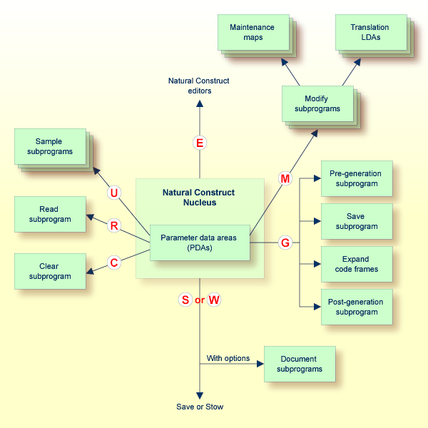
The Natural Construct nucleus is a sophisticated driver program that assembles the model components and sets them in motion. Although it invokes the subprograms at the appropriate time in the generation process and performs the functions common to all models, it is not aware of the code generated by the models.
The nucleus communicates with the model subprograms through standard parameter data areas (PDAs). These PDAs contain fields assigned by Natural Construct, as well as fields that are redefined as required by a model.
The generation process uses each model component at a different time. The following diagram illustrates the components of a model and how they interact with each other and the nucleus. The large letters in red correspond to the function codes a user enters on the Generation main menu to invoke the corresponding subprogram(s):
This section describes how to build a new Natural Construct model. These steps are:
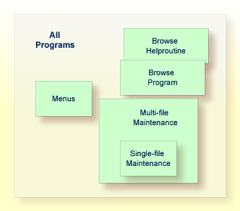
Before you can build the new model, you must decide what type of module the model will generate. The following diagram illustrates the varying scope and overlapping functionality of different module types:
If your model contains many parameters (one that generates complex modules with broad functionality), it may:
Confuse and frustrate developers
Lengthen the time it takes developers to specify parameters
Require complex code frames with many conditions
Make the model so flexible that generated code may deviate from standards
For example, the model should not allow developers to define PF-keys used for standard features (these should be standardized across all applications). On the other hand, these models can be very powerful and flexible — once the developer is familiar with them.
If your model contains few parameters (one that generates simple modules with narrow functionality), it may:
Make the model inflexible
Limit the model's usefulness
On the other hand, these models are simple to use and easy to maintain.
Typically, models generate Natural source code — but the possibilities are endless. Natural Construct was designed to generate text in any form: Unix scripts, JCL, COBOL, Visual Basic, C++, HTML scripts, etc.
As a general rule, you will want your models to generate common modules that cannot be parameterized at execution time. This type of module often involves file accesses or compile-time statements, such as:
map names
parameter lists
FORMAT statements
I/O statements
file definitions
Alternately, you may want the model to generate modules that can be parameterized at execution time but are hardcoded for performance reasons (menus, for example).
Once you determine the purpose and scope of the model, you can create a Natural module (program, subprogram, map, etc.) to base your model on. This module should perform all the functions you defined for the scope of the model.
If the scope contains mutually-exclusive options, you should prepare several prototypes. For example, if the Natural code to maintain a file with a superdescriptor is significantly different from the code that maintains a file with a descriptor, create two prototypes. If possible, generate the more complex prototype first and add the simpler prototype later.
After creating your prototype Natural program, perform the following checks:
Ensure that the program is fully commented
Check the code indentation
Check the clarity of the program
Ensure that the program conforms to standards
Evaluate the efficiency of the program
Ensure that variable names are sorted
After you have scrutinized the prototype as thoroughly as possible, have someone else perform the same checks and tests.
The basic premise behind program generation is to take a working module that performs a fixed function and generalize the module so it performs varying functions based on parameter values. To isolate the parameters:
The first step is to determine which program lines remain constant in the generalized module and which lines vary. If the prototype reads a file and displays information, for example, the file and information varies with each generation. Therefore, this information must be parameterized. To make the prototype easier to generate, try to reduce the number of parameters in your prototype without affecting the functionality.
Programs often contain several instances of the same parameter. These can be reduced to a single instance of the parameter by using a constant variable. Consider the following examples:
| Redundant Parameters | Single Parameter |
|---|---|
DEFINE DATA LOCAL 01 #A(A1/1:50 . . END-DEFINE . . IF #A(#CUR:50) NE ' ' THEN FOR #I = #CUR TO 50 etc. |
DEFINE DATA LOCAL 01 #ASIZE(P3) CONST<50> 01 #A(A1/1:#ASIZE) . END-DEFINE . . IF #A(#CUR:#ASIZE) NE ' ' THEN FOR #I = #CUR TO #ASIZE etc. |
This technique makes the prototype easier to generate, since there are fewer parameter instances. In addition, the generated programs are easier to read, since it is more obvious that the constant value always refers to the same thing.
Ensure that your prototype does not contain hardcoded parameters that could easily be calculated at runtime. Consider the following examples:
| Unnecessary Constant | Determine at Runtime |
|---|---|
DEFINE DATA LOCAL
   01 #MAX-LINES(P3) CONST <15>
   01 #LINE-NR(P3/1:#MAX-LINES)
INIT<1,2,3,4,5,6,7,8,9,10,11,12,13,
               15>
END-DEFINE |
DEFINE DATA LOCAL 01 #MAX-LINES(P3) CONST <15> 01 #LINE-NR(P3/1:#MAX-LINES) 01 #I (P3) END-DEFINE FOR #I = 1 TO #MAX-LINES ASSIGN #LINE-NR (#I) = #I END-FOR |
Both the INIT statement on the left and the FOR loop on the right initialize an array with consecutive numbers. However, the code on the right does not vary based on the value of #MAX-LINES. No special processing is required to generate the code on the right, as it is constant for each generation. To make the prototype more flexible and easier to generate, use Natural system variables to determine the values at runtime.
Note:
Ensure you do not sacrifice program efficiency to achieve this
goal.
Once you have written and tested your prototype, save it in the SYSCST library.
This section covers the following topics:
If the prototype program is large, you can create multiple code frames with a portion of the program in each code frame. You can also use nested code frames.
 To create the code frames
Invoke the Code Frame editor.
Read your prototype into the editor.
Determine the parameters required for the code frame.
These include substitution parameters, code frame conditions, generation subprograms, nested code frames, and user exits. The following example shows a code frame in the Code Frame editor:
Frame .............. PRSLCC9                                        SIZE 1125
Description ........ Browse Select Code©) Inline Subroutines       FREE 59940
>                                              > + ABS X X-Y X S 18   L 1
All...+....1....+....2....+....3....+....4....+....5....+....6....+....7.. T C
  *
  * Subroutines (in alphabetical order).
  * Check wildcard processing                                              *
  CHECK-WILD-CHARACTER                                                       1
  CUSLCWC?                                                                 F "
  * Initializations                                                        *
  CUSLCI?                                                                  F
   Subprogram: CUSCGBND Parameter: INITIALIZE                              N
  * Initialize the input key to the minimum key value specified
    ASSIGN #INPUT.&PRIME-KEY = #MIN-KEY-VALUE
  Process Selected Column or Record                                        *
  PROCESS-SELECTION-COLUMN OR PROCESS-SELECTED-RECORD                        1
  CUSLCPS?                                                                 F "
  * Final Processing                                                       *
  CUSLCFP?                                                                 F
  MISCELLANEOUS-SUBROUTINES                                                U
  PERFORM FINAL-PROCESSING
  END
....+....1....+....2....+....3....+....4....+....5....+....6....+....7.. T |
For a description of the Code Frame editor, see Using the Code Frame Editor. For information about edit commands, see Edit Commands.
The code frame example above demonstrates different methods of supplying parameters for a code frame. These methods are:
One type of code frame parameter is substitution parameters. These parameters are always present in the same format, but their values change. You can usually assign substitution parameters by replacing the values with unique substitution strings. To identify a parameter as a substitution, use an ampersand (&) at the beginning of the substitution string in the editor.
The code frame example above contains the following substitution parameter:
* Initialize the input key to the minimum key value specified
  ASSIGN #INPUT.&PRIME-KEY = #MIN-KEY-VALUE
Values are substituted after the module is fully generated. The unique identifier (&PRIME-KEY in the example above) is substituted for the derived value by placing the unique identifier and the value in the Natural stack.
Note:
For more information about substitution during the post-generation
phase, see Post-Generation
Subprogram.
The following stipulations apply:
Substitution parameters cannot span multiple lines.
Substitution parameters always begin with an ampersand (&).
The substitution string can be up to 32 characters in length.
The substitution value can be up to 72 characters in length.
The name of the parameter should correspond to the name of the model PDA variable that supplies the value. For example, &VAR is assigned the value of #PDA-VAR or #PDAX-VAR. Following this naming convention makes it easier to generate the model subprograms using the supplied models. For more information about the model PDA, see Model PDA.
A generation subprogram can supply the code frame parameters. When a substitution parameter spans more than one line, varies in length, or performs complex calculations (centering, for example), you can supply the parameters in a generation subprogram.
An example of this type of parameter is a file view where the developer specifies the name of the file to use. Instead of supplying a list of the fields in the view, you can specify the name of a subprogram to supply this list.
To indicate that a subprogram is called on this line, enter "N" (Natural subprogram) in the corresponding T (Type) field. To pass a parameter to the subprogram, specify the parameter value after the subprogram name. The parameter can be a literal string, 1–32 characters in length.
Natural Construct passes the following structures to each generation subprogram:
Model PDA (CUxxPDA), containing model-specific parameters
CSASTD, containing the standard messaging parameters
CU—PDA, containing the standard generation parameters (the #PDA-FRAME-PARM field in this PDA passes the parameter literal string)
The following code frame line indicates that the CUSCGBND subprogram is invoked from this point in the code frame and passed the INITIALIZE value:
Subprogram: CUSCGBND Parameter: INITIALIZE N
Because code frame parameters are supplied in a generation subprogram, the same subprogram can be invoked several times within the code frame. The subprogram uses the value of the passed parameter to determine what to generate each time.
Another method of supplying parameters to a code frame is to use nested code frames. As with generation subprograms, nested code frames can perform substitutions on lines of varying length. In fact, nested code frames have all substitution options available to the calling code frame. For example, a nested code frame can have substitution parameters, generation subprograms, and its own nested code frames.
All code frames supplied with Natural Construct end with 9 (see the description of the Code frame(s) field in Maintain Models Function) and 8 is reserved for any future updates. When you reference a code frame from within another code frame, use a question mark (?) instead of 9. The ? indicates a hierarchy structure in which Natural Construct uses the code frame with the lowest number during generation.
For specific hardcoded references, you can specify a nested code frame without using the question mark (?) — but if you want to change what the nested code frame generates, you must modify every calling code frame and its reference. When you use the question mark (?) character, Natural Construct automatically calls your new version of the nested code frame.
Note:
To make nested code frames more reusable across multiple models, it
is important to use the same naming conventions. In this way, the nested code
frame logical and substitution parameters are always available within the model
PDAs.
To indicate that another code frame is called on a Code Frame editor line, enter "F" in the corresponding T (Type) field. The following code frame line indicates that the CUSLCIn code frame supplies parameters for the code frame, where n is a number from 1 to 9:
CUSLCI? F
To modify a supplied code frame, copy the code frame, change the 9 to a lesser number from 1 to 7 (8 is used for code frame fixes supplied between releases), and modify the code frame as desired. The next time Natural Construct calls that code frame, the one you created with the lesser number is used. For example, you can copy the CUSLCI9 code frame, change the name to CUSLCI7, and edit it as desired. The next time Natural Construct calls CUSLCI?, CUSLCI7 is used.
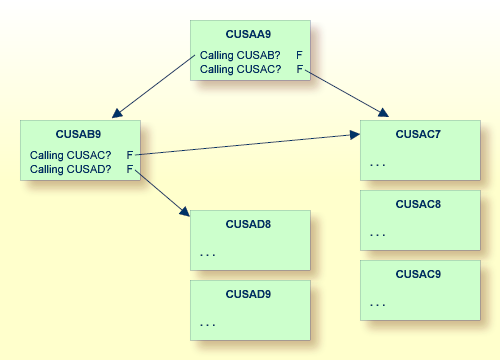
In the following example, the CUSAA9 code frame has two nested code frames (CUSAB? and CUSAC?). The arrows indicate which code frame is used:
Tip:
Ensure that you do not create endless loops within nested code
frames; endless loops result when a code frame calls itself, either directly or
indirectly as a nested code frame.
Parameters for a code frame can also be supplied by user exits. User exits provide maximum flexibility for defining parameters because parameters are specified in the form of embedded Natural code. User exits allow programmers/analysts to provide specialized portions of code at various points within the generated module.
To supply parameters for a code frame through a user exit
Enter the name of the user exit in the text portion of a line.
Enter "U" in the corresponding T (Type) field.
Optionally, you can specify additional attributes by entering ".E" at the beginning of the user exit line.
For example:
 Frame .............. CUSLD9                                         SIZE 5973
 Description ........ Browse Select Subp. Define Data Area           FREE 54796
 >                                              > + ABS X X-Y _ S 102  L 1
 Top...+....1....+....2....+....3....+....4....+....5....+....6....+....7.. T C
   CU--B?                                                                   F
   DEFINE DATA
   GDA-SPECIFIED                                                              1
     GLOBAL USING &GDA &WITH-BLOCK                                            "
     PARAMETER
     01 #PDA-KEY(&PARM-NAT-FORMAT)  /* Start/Returned key.
     VARIABLE-MIN-MAX AND PREFIX-IS-PDA-KEY                                   1
     01 REDEFINE #PDA-KEY                                                     "
       02 #PDA-KEY-PREFIX(&PREFIX-NAT-FORMAT)                                 "
     PARAMETER USING CDSELPDA /* Selection info
     PARAMETER USING CU—PDA  /* Global parameters
     PARAMETER USING CSASTD   /* Message information
   .eRAMETER-DATA                                                           U
     LOCAL USING CDDIALDA /* Used by dialog objects.
     LOCAL USING CDENVIRA /* Used to capture/restore previous environment.
   DIRECT-COMMAND-PROCESSING                                                  1
     LOCAL USING CDGETDCA /* Used to get direct command info.                 "
   MULTIPLE-WINDOWS                                                           1
   ....+....1....+....2....+....3....+....4....+....5....+....6....+....7.. T
CUSLD9 read |
Press Enter.
The Maintain User Exit window is displayed. For example:
CSMUSEX                       Natural Construct
Jul 05                        Maintain User Exit                      1 of 1
 User exit name ......... START-OF-PROGRAM
 Code frame name ........ COBB9    Conditional  N
 User exit required ..... _
 Generate as subroutine . _
 Sample subprogram ...... ________        GUI sample subprogram .. ________
 Default user exit code .
   *_______________________________________________________________________
   * Specify code to be executed at the beginning of the object subprogram.
   * This might include security checking logic.___________________________
   ________________________________________________________________________
   ________________________________________________________________________
   ________________________________________________________________________
   ________________________________________________________________________
   ________________________________________________________________________
   ________________________________________________________________________
   ________________________________________________________________________
 Enter-PF1---PF2---PF3---PF4---PF5---PF6---PF7---PF8---PF9---PF10--PF11--PF1
help retrn |
Use this window to specify information about the user exit. The fields in this window are:
| Field | Description |
|---|---|
| User exit name | Name of the user exit. |
| Code frame name | Name of the code frame for the user exit. |
| Conditional | Condition code for the user exit. If the user exit is conditional (required only under certain conditions), "Y" is displayed. If it is not conditional, "N" is displayed. |
| User exit required | If this field is marked, the user exit is required; if this field is blank, the user exit is optional. |
| Generate as subroutine | If the user exit is used in more than one
place in the module, enter "Y". The code is
generated as an inline subroutine. During generation, Natural
Construct places the code in a subroutine with the same name as
the user exit. This allows you to execute the code several times using a
PERFORM user-exit-name statement.
If the user exit is optional, the PERFORM statement can be conditional on the presence of the user exit itself (for information, see Use Code Frame Conditions). Regardless of whether user exits are generated as subroutines or embedded code, use the DEFINE EXIT keyword to specify all user exits. |
| Sample subprogram | If a subprogram contains the sample code for
the user exit, enter the name of the subprogram. The sample code is generated
after the developer enters the SAMPLE command in the User Exit editor and
selects an exit.
Natural Construct passes three parameter data areas (PDAs) to each sample subprogram: the model PDA, CU—PDA, and CSASTD. For more information, see Step 6: Create the Model PDA. Note: |
| GUI sample subprogram | GUI sample subprogram invoked when the code is being generated from the client. This subprogram should not display input panels. If the sample subprogram does not use input panels, it can be used in the GUI sample subprogram. If the sample subprogram includes input panels, create a copy and modify it to use the defaults. |
| Default user exit code | If complex processing or calculations are
not required, you can enter up to 10 lines of sample code. This code becomes
the default sample code for this user exit.
Note: |
Frequently, a block of statements is inserted in a program based on a
condition or combination of conditions specified in the code frame. In the
following example, the INPUT WITH TEXT+MSG USING MAP '&MAP-NAME'
INPUT statement is generated if a map is used. Otherwise, the
INPUT(AD=OI) statement is generated:
Top...+....1....+....2....+....3....+....4....+....5....+....6....+....7.. T C MAP-USED 1 INPUT WITH TEXT + MSG USING MAP '&MAP-NAME' " ELSE 1 INPUT(AD=OI) *PROGRAM #HEADER1 " / *DATX #HEADER2 *TIMX " |
Note:
To identify a condition line, enter a number in the
C (Condition) column in the Code Frame editor.
Number "1" initiates a new condition; higher numbers
represent nested conditions that are only evaluated if all active lower
conditions are True.
To identify a statement as conditional, enter """ in the C column. The corresponding statement is included in the generated module only if the current condition is True.
When you use code frame conditions, consider the following points:
The names of conditions must correspond to the names of logical
variables defined in the model PDA, with the #PDAC- prefix removed. (For more
information about the model PDA, see
Step 6: Create the
Model PDA.) The MAP-USED condition, for example,
corresponds to the #PDAC-MAP-USED logical
variable.
Note:
These condition variables must be part of the redefinition of the
#PDA-CONDITION-CODES field in the model PDA.
When Natural Construct generates a module, it checks the condition code values to determine whether the condition is True. It then resets the conditions before invoking the maintenance subprograms. Condition codes should be selectively set to True by either the pre-generation subprogram or one of the maintenance subprograms.
Conditions can be negated, ANDed and ORed (in order of precedence).
Conditions can be nested and ELSEed (ELSE refers back to the previous condition at the same level number).
The RETURN-TO-CONDITION keyword can close levels of conditioning.
A special condition line can check for the existence of a specific
user exit. To specify this type of condition, enter the name of the user exit
as the condition value and specify a line type of
"X". These conditions cannot be negated, ANDed, or
ORed, but can be nested. They do not require a corresponding
#PDAC variable.
The following example shows code frame conditions:
Frame ..............ABC 			                                SIZE 68
Description ........Example of conditions	              FREE 36676
  >                                      > + ABS X X-Y _ S 21 L 1
Top.+...1...+...2...+...3...+...4...+...5...+...6...+...7..   T C Notes
MAP-USED                                                           1
INPUT WITH TEXT + MSG USING MAP '&MAP-NAME'1                    "  1
ELSE			                                                            1
INPUT(AD=OI) *PROGRAM #HEADER1                                  "  2
/ *DATX #HEADER2 *TIMX                                          "  2
ROOM-FOR-SKIP                                                      2
/			                                                            "  3
RETURN-TO-CONDITION                                                1
/ 20T #FUNCTION-HEADING                                         "  2
 NOT MAP-CONTAINS-PARAMETERS                                       2
 CODE1-SPECIFIED                                                   3
/ 16T #CODE(1) 20T #FUNCTION(1)                                 "  4
 CODE2-SPECIFIED	                                                  3
/ 16T #CODE(2) 20T #FUNCTION(2)                                 "  5
     .
     .
     .
 CODE12-SPECIFIED                                                  3
/ 16T #CODE(12) 20T #FUNCTION(12)                               "  6
 RETURN-TO-CONDITION                                               2
/ 11T 'Code:' #CODE(AD=M)                                       "  7
 ELSE		                                                            2
Subprogram: CUMNGIN  Parameter                               N  "  8
RETURN-TO-CONDITION                                                1
21/1 'Direct Command:' #COMMAND(AD=M)                           "  2
RESET +MSG                                                         9
AFTER-INPUT
AFTER-INPUT                                                  X     1
PERFORM AFTER-INPUT " 10 |
Higher-level numbers (nested conditions) are always joined with an AND statement to previous lower condition numbers.
The lines of code corresponding to each note number in the above example are inserted into the generated module when the following Boolean conditions are met:
| Note Number | Boolean Condition |
|---|---|
| 1 | #PDAC-MAP-USED = TRUE |
| 2 | #PDAC-MAP-USED = FALSE |
| 3 | #PDAC-MAP-USED = FALSE and
#PDAC-ROOM-FOR-SKIP = TRUE |
| 4 | #PDAC-MAP-USED = FALSE and
#PDAC-MAP-CONTAINS-PARAMETERS = FALSE and #PDAC-CODE1-SPECIFIED = TRUE |
| 5 | #PDAC-MAP-USED = FALSE and
#PDAC-MAP-CONTAINS-PARAMETERS = FALSE and #PDAC-CODE2-SPECIFIED = TRUE |
| 6 | #PDAC-MAP-USED = FALSE and
#PDAC-MAP-CONTAINS-PARAMETERS = FALSE and #PDAC-CODE12-SPECIFIED = TRUE |
| 7 | #PDAC-MAP-USED = FALSE and
#PDAC-MAP-CONTAINS-PARAMETERS = FALSE |
| 8 | #PDAC-MAP-USED = FALSE and
#PDAC-MAP-CONTAINS-PARAMETERS = TRUE |
| 9 | Line is inserted unconditionally. |
| 10 | Line is inserted only when the AFTER-INPUT user exit is specified in the User Exit editor before the module is generated. |
Use the Maintain Models panel to define your model.
To display the Maintain Models panel
Log onto the SYSCST library.
Enter "MENU" at the Next prompt (Direct Command box for Unix).
The Administration main menu is displayed.
Enter "M" in Function.
The Maintain Models panel is displayed. For example:
CSDFM                    N a t u r a l   C o n s t r u c t              CSDFM0
Aug 17                          Maintain Models                         1 of 1

Action ..................... __ A,B,C,D,M,N,P,R
Model ...................... ________________________________
Description ........ __________________________________________________________

  PDA name ................. ________     Status window ............ _
  Programming mode ......... __           Comment start indicator .. ___
  Type ..................... _            Comment end indicator .... ___

  Code frame(s) ............ ________  ________  ________  ________  ________
  Modify server specificatn  ________  ________  ________  ________  ________
                             ________  ________  ________  ________  ________
  Modify client specificatn  ________  ________  ________  ________  ________
                             ________  ________  ________  ________  ________

  Clear specification ...... ________     Post-generation .......... ________
  Read specification ....... ________     Save specification ....... ________
  Pre-generation ........... ________     Document specification ... ________
Command ............ __________________________________________________________
Enter-PF1---PF2---PF3---PF4---PF5---PF6---PF7---PF8---PF9---PF10--PF11--PF12---
help retrn quit frame main |
Use this panel to specify the names of the model components (the generation subprograms require this model definition); the specified components do not have to currently exist. When naming the model components, use the naming conventions described in the following section.
For a description of the Maintain Models panel, see Maintain Models Function.
Standardizing the names of the various components of a model makes it easier to write and debug models. Supplied model subprograms, maps, and data areas are typically named CUxx, where xx uniquely identifies each model and y identifies each panel. When naming model components, we recommend the following naming conventions:
| Name | Model Component |
|---|---|
| CUxxPDA | Parameter data area. |
| CUxxR | Read subprogram. |
| CUxxC | Clear subprogram. |
| CUxxMA | First maintenance subprogram. |
| CUxxMAn | Map associated with the first maintenance
subprogram.
|
| CUxxMAL | Translation local data area (LDA) associated with the first maintenance subprogram. A translation LDA contains the names of all variables that are initialized to the maintenance map text and can be translated. You cannot dynamically translate a map to another language unless the module that invokes the map has a corresponding translation LDA. |
| CUxxMB | Second maintenance subprogram. |
| CUxxMBn | Map associated with the second maintenance subprogram. |
| CUxxMBL | Translation LDA associated with the second maintenance subprogram. |
| CUxxSyyy | Sample user exit code subprograms, where yyy is a 1–3 character suffix that uniquely identifies each sample subprogram. For example, the CUFMSRIN sample subprogram supplies REINPUT statements for the Maint model (if required). |
| CUxxGyyy | Generation subprograms, where yyy is a 1–3 character suffix that uniquely identifies each generation subprogram. For example, the CUMNGGL subprogram generates parameter variables for the Menu model (when a length and format are specified). |
| CUxxPR | Pre-generation subprogram. |
| CUxxPS | Post-generation subprogram. |
| CUxxS | Save subprogram. |
| CUxxD | Documentation subprogram. |
| WCNxxMy | Construct Program Generation plug-in
maintenance subprogram.
Note: |
| WCDxx | Construct Program Generation plug-in dialog.
Note: |
To modify the supplied Natural Construct models, copy the subprograms and change the prefix from CU (or WC) to CX. This way, you can identify the modified subprograms and include any changes in future versions of Natural Construct.
After defining a model, it can be used in the Generation subsystem.
All models require three parameter data areas (PDAs). Two of the data areas are supplied with Natural Construct and the model PDA is user-created for each individual model.
PDAs pass information between the nucleus and the model and code frame subprograms. Every model subprogram uses the following external PDAs:
| PDA | Description |
|---|---|
| Model PDA | User-created and named CUxxPDA, where xx uniquely identifies the model. This PDA contains variables and conditions specific to the model. It is the only PDA you must create. Use the CST-PDA model to create the model PDA (see Parameters for the CST-PDA Model). |
| CU—PDA | Supplied with Natural Construct. |
| CSASTD | Supplied with Natural Construct. |
These PDAs must contain the following fields:
| PDA | Required Fields and Format |
|---|---|
| Model PDA (varies for each model) | #PDA-CONDITION-CODES (L/1:75)
#PDA-USER-AREA (A100/1:40) |
| CU--PDA (same for every model) | #PDA-MODE (A2)
#PDA-OBJECT-TYPE (A1) #PDA-MODIFY-HEADER1 (A60) #PDA-MODIFY-HEADER2 (A54) #PDA-LEFT-PROMPT (A11) #PDA-LEFT-MORE-PROMPT (A9) #PDA-RIGHT-PROMPT (A11) #PDA-RIGHT-MORE-PROMPT (A9) #PDA-PHASE (A1) #PDA-DIALOG-METHOD (I1) #PDA-TRANSLATION-MODE (L) #PDA-USERX-NAME (A10) #PDA-PF-NAME (A10/1:12) #PDA-MAIN-NAME (A10) #PDA-RETURN-NAME (A10) #PDA-QUIT-NAME (A10) #PDA-TEST-NAME (A10) #PDA-BACKWARD-NAME (A10) #PDA-FORWARD-NAME (A10) #PDA-LEFT-NAME (A10) #PDA-RIGHT-NAME (A10) #PDA-HELP-NAME (A10) #PDA-AVAILABLE1-NAME (A10) #PDA-AVAILABLE2-NAME (A10) #PDA-AVAILABLE3-NAME (A10) #PDA-PF-NUMBER (N2/1:12) #PDA-MAIN (N2) #PDA-RETURN (N2) #PDA-QUIT (N2) #PDA-TEST (N2) #PDA-BACKWARD (N2) #PDA-FORWARD (N2) #PDA-LEFT (N2) #PDA-RIGHT (N2) #PDA-HELP (N2) #PDA-AVAILABLE1 (N2) #PDA-AVAILABLE2 (N2) #PDA-AVAILABLE3 (N2) #PDA-PF-KEY (A4) #PDA-PF-MAIN (A4) #PDA-PF-RETURN (A4) #PDA-PF-QUIT (A4) #PDA-PF-TEST (A4) #PDA-PF-BACKWARD (A4) #PDA-PF-FORWARD (A4) #PDA-PF-LEFT (A4) #PDA-PF-RIGHT (A4) #PDA-PF-HELP (A4) #PDA-PF-AVAILABLE1 (A4) #PDA-PF-AVAILABLE2 (A4) #PDA-PF-AVAILABLE3 (A4) #PDA-TITLE (A25) #PDA-GEN-PROGRAM (A8) #PDA-MODEL-VERSION (N2.2) #PDA-HELP-INDICATOR (A4) #PDA-USER-DEFINED-AREA (A1/1:100) #PDA-UNDERSCORE-LINE (A80) #PDA-RIGHT-PROMPT-OF (A4) #PDA-DISPLAY-INDICATOR (A4/1:10) #PDA-CURS-FIELD (I4) #PDA-CV1 (C) #PDA-CV2 (C) #PDA-CV3 (C) #PDA-CV4 (C) #PDA-CV5 (C) #PDA-CV6 (C) #PDA-CV7 (C) #PDA-CV8 (C) #PDA-SCROLL-INDICATOR (A4) #PDA-DYNAMIC-ATTR-CHARS (A1/1:13) #PDA-FRAME-PARM (A32) #PDA-SYSTEM (A32) |
| CSASTD (same for every model) | MSG (A79)
MSG-NR (N4) MSG-DATA (A32/1:3) RETURN-CODE (A1) ERROR-FIELD (A32) ERROR-FIELD-INDEX1 (P3) ERROR-FIELD-INDEX2 (P3) ERROR-FIELD-INDEX3 (P3) Note: |
The following sections describe the layout of these PDAs.
The following example shows a model PDA:
Parameter CUETPDA   Library SYSCST                             DBID  19 FNR  28
Command                                                                     > +
I T L Name                             F Leng Index/Init/EM/Name/Comment
Top - -------------------------------- - ---- ---------------------------------
    1 CUETPDA                                 /* Construct Model PDA
    2 #PDA-CONDITION-CODES             L      (1:75) /* Conditions in frames
  R 2 #PDA-CONDITION-CODES                    /* REDEF. BEGIN : #PDA-CONDITION
    3 #PDAC-USE-MSG-NR                 L      /* TRUE IF MESSAGE NUMBERS ARE U
    3 #PDAC-FILE-NAME-SPECIFIED        L
    3 #PDAC-FIELD-NAME-SPECIFIED       L
    3 #PDAC-PDA-SPECIFIED              L
    3 #PDAC-COMPLEX-FIELD              L      /* Field is a PE, MU a STRUCT or
  *                                           /* REDEFINE
    3 #PDAC-SCROLLING                  L      /* Scrolling
    3 #PDAC-NATURAL-WINDOWS            L      /* Set window sizes
    3 #PDAC-WINDOW-LENGTH              L      /* Set window line length
    3 #PDAC-WINDOW-COLUMN              L      /* Set window column height
    3 #PDAC-WINDOW-BASE                L      /* Set window base
    3 #PDAC-DEFINE-WINDOW              L      /* Generate DEFINE WINDOW
    2 #PDA-USER-AREA                   A  100 (1:40) /* Area for INPUT and der
  R 2 #PDA-USER-AREA                          /* REDEF. BEGIN : #PDA-USER-AREA
    3 RESET-STRUCTURE                         /* Use for resetting non-alpha
  *                                           /* fields in Clear Subprogram.
    4 #PDAX-DESCS                      A   55 (1:4) /* description
    4 #PDAX-USE-MSG-NR                 L
  *
  *   Modify screen 2
    4 #PDAX-PDA                        A    8 /* PDA with display info.
    4 #PDAX-FILE-NAME                  A   32 /* File name
    4 #PDAX-FIELD-NAME                 A   32 /* Field name
    4 #PDAX-MAP-NAME                   A    8 /* Input using map
    4 #PDAX-LINES-PER-SCREEN           N    3 /* Number of lines per screen
  *
  *   used to generate a
  *   DEFINE WINDOW statement.
    4 DEFINE-WINDOW-INFO
    5 #PDAX-WINDOW-SIZE                A    6 /* Window size
  R 5 #PDAX-WINDOW-SIZE                       /* REDEF. BEGIN : #PDAX-WINDOW-S
    6 #PDAX-WINDOW-SIZE-WIDTH          N    3 /* Window size width
    6 #PDAX-WINDOW-SIZE-HEIGHT         N    3 /* Window size height
    5 #PDAX-WINDOW-BASE                A    6 /* Window base
  R 5 #PDAX-WINDOW-BASE                       /* REDEF. BEGIN : #PDAX-WINDOW-B
    6 #PDAX-WINDOW-BASE-LINE           N    3 /* Window base line
    6 #PDAX-WINDOW-BASE-COLUMN         N    3 /* Window base column
    5 #PDAX-WINDOW-FRAME-OFF           L      /* Window frame off
    5 #PDAX-WINDOW-TITLE               A   65 /* Window title
    5 #PDAX-WINDOW-CONTROL-SCREEN      L      /* Window control screen on
    5 #PDAX-DEFINE-WINDOW              L      /* Use DEFINE WINDOW statement
    4 #PDA-FIELD-TYPE                  A    2 /* Field type: GR,PE,PC,MU,MC
  *                                           /* S(Structure), F(Single Field)
  *                                           /* R(REDEFINE)
    4 #PDA-FIELD-REDEFINED             L
    4 #PDA-LEVEL-NUMBER                N    1
    4 #PDA-FIELD-FORMAT                A    1
    4 #PDA-FIELD-LENGTH                N  3.1
  R 4 #PDA-FIELD-LENGTH
    5 #PDA-UNITS                       N    3
    5 #PDA-DECIMALS                    N    1
    4 #PDA-FROM-INDEX                  N    5 (1:3)
    4 #PDA-THRU-INDEX                  N    5 (1:3)
    4 #PDA-FIELD-RANK                  N    1
    4 #PDA-FILE-CODE                   P    8 /* file code for security check
    4 #PDA-MAX-LINES                   N    5 /* Num. of occurrences for PE/MU
    4 #PDA-WFRAME                      A    1 /* Parameters for window setting
    4 #PDA-WLENGTH                     A    3
    4 #PDA-WCOLUMN                     A    3
    4 #PDA-WBASE                       A    7
The fields in the model PDA are described in the following sections.
This field (L/1:75) is an array of condition codes that allow you to define up to 75 logical conditions for each model. The field is usually redefined into separate logical variables, one for each condition variable used by the model code frames. The name of the logical condition variable in the PDA must be the same as the condition, with a #PDAC- prefix added.
When a module is generated, the condition values are checked to determine whether the condition is True. The conditions are reset before the maintenance subprograms are invoked. Along with the pre-generation subprogram, the maintenance subprograms assign all True condition values.
Note:
To make nested code frames more reusable across multiple models, it
is important to use exactly the same naming conventions. In this way, the
nested code frame logical and substitution parameters are always available to
the model PDAs.
This field (A100/1:40) defines a large block of data that is passed between the Natural Construct nucleus and the model subprograms. Always redefine this field into separate fields that refer to the module being generated. The following information can be passed:
Data entered by the developer on a maintenance panel. The names of the fields that receive the parameters should be prefixed by #PDAX- and appear first in the redefinition of #PDA-USER-AREA. Usually, the values for these fields are written as comments at the beginning of the generated program. This allows Natural Construct to read the parameters for subsequent regeneration.
You can also group a series of related parameters into a single external parameter by redefining the #PDAX- variable into sub-fields. This technique reduces the number of comment lines at the beginning of a generated program.
Note:
This technique should only be used when the length of the
sub-fields does not change.
Data calculated during the generation process and shared with the model subprograms. The variable names should be prefixed by #PDA- and appear second in the redefinition of #PDA-USER-AREA (after the #PDAX- variables).
The pre-generation subprogram assigns these internal generation variables; all subsequent code frame and model subprograms can use the values.
When you use substitution parameters in code frames, a variable with the same name and a #PDAX- or #PDA- prefix should be in the redefinition of the #PDA-USER-AREA variable. For example, the &MAX-SELECTIONS substitution parameter value should be supplied by the #PDA-MAX-SELECTIONS variable or the #PDAX-MAX-SELECTIONS variable.
Note:
To make nested code frames more reusable across multiple models,
it is important to use exactly the same naming conventions. In this way, the
nested code frame logical and substitution parameters are always available to
the model PDAs.
The following example shows the CU—PDA data area:
Parameter CU-PDA   Library SYSCST                              DBID  19 FNR  28
Command                                                                     > +
I T L Name                             F Leng Index/Init/EM/Name/Comment
Top - -------------------------------- - ---- ---------------------------------
  *   Parameters used by all user
  *   subprograms
  *
    1 CU-PDA
  *
  *   Parameters used by generating
  *   subprograms
    2 #PDA-MODE                        A    2 /* R=Report, S=Struct, SD=Str data
    2 #PDA-OBJECT-TYPE                 A    1 /* P=Program, N=Subprogram,etc.
  *
  *
  *   Parms used by modify screens
    2 #PDA-MODIFY-HEADER1              A   60 /* First heading on modify scr
    2 #PDA-MODIFY-HEADER2              A   54 /* Second heading on modify scr
    2 #PDA-LEFT-PROMPT                 A   11 /* Date
  R 2 #PDA-LEFT-PROMPT
    3 #PDA-LEFT-MORE-PROMPT            A    9
    2 #PDA-RIGHT-PROMPT                A   11 /* n of n
  R 2 #PDA-RIGHT-PROMPT
    3 #PDA-RIGHT-MORE-PROMPT           A    9
    2 #PDA-PHASE                       A    1 /* Modify, Generate, Clear etc.
    2 #PDA-DIALOG-METHOD               I    1 /* See CSLMMETH
  *                                           /* 1 = Input + Validate
  *                                           /* 2 = Input no validate
  *                                           /* 3 = Validate no input
  *                                           /* 4 = Validate input on error
    2 #PDA-TRANSLATION-MODE            L      /* Translation mode
  *
  *   The following PF key variables          are only required if the modify
  *   or sample program requires the          use of additional PF keys other
  *   than the standard MAIN, RETURN,         QUIT, HELP keys.
  *
  *   Place the following key names at        the bottom of map instead of
  *   using the KD option. The modify         program should reset the keys
  *   that are not being used or              assign the available key names
  *   to set additional keys.
  *
    2 #PDA-USERX-NAME                  A   10 /* User Exit name.
    2 #PDA-PF-NAME                     A   10 (1:12)
  R 2 #PDA-PF-NAME                            /* REDEF. BEGIN : #PDA-PF-NAME
    3 #PDA-MAIN-NAME                   A   10 /* Main menu key name.
    3 #PDA-RETURN-NAME                 A   10 /* Return key name.
    3 #PDA-QUIT-NAME                   A   10 /* Quit key name.
    3 #PDA-TEST-NAME                   A   10 /* Test key name.
    3 #PDA-BACKWARD-NAME               A   10 /* Bkwrd key name.
    3 #PDA-FORWARD-NAME                A   10 /* Frwrd key name.
    3 #PDA-LEFT-NAME                   A   10 /* Left key name.
    3 #PDA-RIGHT-NAME                  A   10 /* Right key name.
    3 #PDA-HELP-NAME                   A   10 /* Help key name.
    3 #PDA-AVAILABLE1-NAME             A   10 /* Not used by default.
    3 #PDA-AVAILABLE2-NAME             A   10 /* Not used by default.
    3 #PDA-AVAILABLE3-NAME             A   10 /* Not used by default.
  *
  *   This array contains the PF-KEY          number associated with each
  *   standard key setting as well as         the numbers of the available
  *   numbers for non-standard key            use.
    2 #PDA-PF-NUMBER                   N    2 (1:12)
  R 2 #PDA-PF-NUMBER                          /* REDEF. BEGIN : #PDA-PF-NUMBER
    3 #PDA-MAIN                        N    2 /* Main menu key number.
    3 #PDA-RETURN                      N    2 /* Return key number.
    3 #PDA-QUIT                        N    2 /* Quit key number.
    3 #PDA-TEST                        N    2 /* Test key number.
    3 #PDA-BACKWARD                    N    2 /* Bkwrd key number.
    3 #PDA-FORWARD                     N    2 /* Frwrd key number.
    3 #PDA-LEFT                        N    2 /* Left key number.
    3 #PDA-RIGHT                       N    2 /* Right key number.
    3 #PDA-HELP                        N    2 /* Help key number.
    3 #PDA-AVAILABLE1                  N    2 /* Not used by default.
    3 #PDA-AVAILABLE2                  N    2 /* Not used by default.
    3 #PDA-AVAILABLE3                  N    2 /* Not used by default.
  *
  *   This array corresponds to the           above array except the 'PF'
  *   'PF' string prefixes the key            for easy comparison to *PF-KEY.
    2 #PDA-PF-KEY                      A    4 (1:12)
  R 2 #PDA-PF-KEY                             /* REDEF. BEGIN : #PDA-PF-KEY
    3 #PDA-PF-MAIN                     A    4 /* PFnn where nn = main key.
    3 #PDA-PF-RETURN                   A    4
    3 #PDA-PF-QUIT                     A    4
    3 #PDA-PF-TEST                     A    4
    3 #PDA-PF-BACKWARD                 A    4
    3 #PDA-PF-FORWARD                  A    4
    3 #PDA-PF-LEFT                     A    4
    3 #PDA-PF-RIGHT                    A    4
    3 #PDA-PF-HELP                     A    4
    3 #PDA-PF-AVAILABLE1               A    4 /* Not used by default.
    2 #PDA-CV3                         C      /* Special characters in T mode
    2 #PDA-CV4                         C      /* Column headings in T mode
    2 #PDA-CV5                         C      /* CV 5
    2 #PDA-CV6                         C      /* CV 6
    2 #PDA-CV7                         C      /* CV 7
    2 #PDA-CV8                         C      /* CV 8
    2 #PDA-SCROLL-INDICATOR            A    4 /* Scroll region indicator
  *
  *   Dynamic attribute characters
  *   from the control record. The
  *   following index values represent
  *   1=Default, 2=Intensify, 3=Blink,        4=Italics, 5=Underline,
  *   6=Reversed, 7=Blue, 8=Green,            9=White, 10=Pink, 11=Red,
  *   12=Turquoise, 13=Yellow.
    2 #PDA-DYNAMIC-ATTR-CHARS          A    1 (1:13)
  *
  *   Passed parameter from code frame
    2 #PDA-FRAME-PARM                  A   32
    2 #PDA-SYSTEM                      A   32 /* System must exist in dict.
  *
The fields in CU—PDA are described in the following sections:
This field (A2) identifies the programming mode. The value for this field is the programming mode specified on the Maintain Models panel. Valid values for this field are S (structured), SD (structured data), and R (reporting) mode.
This field (A1) identifies the type of module generated. The value for this field is the module type specified on the Maintain Models panel. This field is useful when a model subprogram is associated with multiple models that use different module types. In this case, the presence or format of certain generated code may be dependent on the type of module generated.
This field (A60) contains the description specified on the Maintain Models panel. Maintenance panels use the #HEADER1 variable for the first heading, instead of #PDA-MODIFY-HEADER1. If #HEADER1 has not been assigned a value, it is assigned the contents of #PDA-MODIFY-HEADER1.
This field (A54) contains the description specified on the Maintain Models panel. Maintenance panels use the #HEADER2 variable for the second heading, instead of #PDA-MODIFY-HEADER2. If #HEADER2 has not been assigned a value, it is assigned the contents of #PDA-MODIFY-HEADER2.
This field (A11) is redefined into the #PDA-LEFT-MORE-PROMPT field (A9). The #PDA-LEFT-MORE-PROMPT field indicates the current date. Place this field as an output field in the top left corner of all maintenance panels. (If you require more than nine bytes, you can use the full length of A11.)
This field (A11) is redefined into the #PDA-RIGHT-MORE-PROMPT field (A9). The #PDA-RIGHT-MORE-PROMPT field indicates the current panel and the total number of panels (1 of 4, for example). Place this field as an output field in the top right corner of all maintenance panels. (If you require more than nine bytes, you can use the full length of A11.)
This field (A1) identifies the current phase of the Natural Construct nucleus (see the CSLPHASE data area for an example). Valid values for this field are A (post-generation), B (batch), C (clear), D (default), G (generation), L (translate), M (modify), P (pre-generation), R (read), U (sample user exit), and V (save). The value for this field is typically controlled by the Natural Construct nucleus and should not be manipulated locally.
Note:
Maintenance subprograms are also invoked prior to SAMPLE processing
in the User Exit editor (in which case, the phase is U) and prior to the
generation phase (in which case, the phase is G).
Since some subprograms are invoked during more than one phase, this field activates the subprogram logic for the current phase. For example, the maintenance subprograms performed during the maintenance phase (M) are invoked (with data stacked) during the generation (G) and sample user exit (U) phases. It may be inappropriate for the maintenance subprogram to perform certain processing during any of these phases.
This field (I1) is reserved for future use.
This field (L) is reserved for future use.
This field (A10) is for internal use only.
This field (A10/1:12) is an array containing the names of the standard PF-keys and is redefined into the following fields (A10):
| Field | Description |
|---|---|
| #PDA-MAIN-NAME | Main menu key name. |
| #PDA-RETURN-NAME | Return key name. |
| #PDA-QUIT-NAME | Quit key name. |
| #PDA-TEST-NAME | Test key name. |
| #PDA-BACKWARD-NAME | Backward key name. |
| #PDA-FORWARD-NAME | Forward key name. |
| #PDA-LEFT-NAME | Left key name. |
| #PDA-RIGHT-NAME | Right key name. |
| #PDA-HELP-NAME | Help key name. |
| #PDA-AVAILABLE1-NAME | Not used (by default). |
| #PDA-AVAILABLE2-NAME | Not used (by default). |
| #PDA-AVAILABLE3-NAME | Not used (by default). |
The names are in the same order as the key settings specified on the Natural Construct control record. The name for PF1 is stored in the first position, PF2 is stored in the second position, etc.
You can define special PF-keys for maintenance subprograms (or sample generation subprograms) by specifying the desired PF-key values and names on the Maintain Subprograms panel (S function on the Administration main menu).
Occasionally, a subprogram may need to modify its PF-key assignments based on internal program functions and parameter values. If this is the case, place this array of PF-key names on the model panels and set the appropriate PF-key names (assuming your model supports variable PF-keys).
If a subprogram requires PF-keys for non-standard functions that are not known at compile time, display this array on the map (instead of using the SET KEY statement and the KD option of the FORMAT statement).
This field (N2/1:12) is an array containing the PF-keys that support the standard PF-key functions and is redefined into the following fields (N2):
| Field | Description |
|---|---|
| #PDA-MAIN | Main menu key number. |
| #PDA-RETURN | Return key number. |
| #PDA-QUIT | Quit key number. |
| #PDA-TEST | Test key number. |
| #PDA-BACKWARD | Backward key number. |
| #PDA-FORWARD | Forward key number. |
| #PDA-LEFT | Left key number. |
| #PDA-RIGHT | Right key number. |
| #PDA-HELP | Help key number. |
| #PDA-AVAILABLE1 | Not used (by default). |
| #PDA-AVAILABLE2 | Not used (by default). |
| #PDA-AVAILABLE3 | Not used (by default). |
The values in this array assign a PF-key function to a PF-key number (for indexing on the #PDA-PF-NAME table). The first occurrence contains the PF-key number associated with the "main" function, the second occurrence contains the PF-key number associated with the "return" function, etc.
To include additional PF-keys, use the PF-key corresponding to the numbers assigned to #PDA-AVAILABLE1 through #PDA-AVAILABLE3.
This field (A4) is an array corresponding to the #PDA-PF-NUMBER array (see #PDA-PF-NUMBER) except the values have a PF- prefix. This makes it easy to compare the value of a *PF-KEY system variable to one of the following fields (A4):
| Field | Description |
|---|---|
| #PDA-PF-MAIN | PFnn, where nn is the main menu key number. |
| #PDA-PF-RETURN | PFnn, where nn is the return key number. |
| #PDA-PF-QUIT | PFnn, where nn is the quit key number. |
| #PDA-PF-TEST | PFnn, where nn is the test key number. |
| #PDA-PF-BACKWARD | PFnn, where nn is the backward key number. |
| #PDA-PF-FORWARD | PFnn, where nn is the forward key number. |
| #PDA-PF-LEFT | PFnn, where nn is the left key number. |
| #PDA-PF-RIGHT | PFnn, where nn is the right key number. |
| #PDA-PF-HELP | PFnn, where nn is the help key number. |
| #PDA-PF-AVAILABLE1 | Not used (by default). |
| #PDA-PF-AVAILABLE2 | Not used (by default). |
| #PDA-PF-AVAILABLE3 | Not used (by default). |
Note:
The PF-key variables defined in this PDA allow your models to
automatically use the PF-key values and names specified on the Natural
Construct control record. If you do not require this flexibility, use hardcoded
PF-key values and names.
This field (A25) contains the title of the module that is generated, which is required for the generation process. The title identifies the module for the List Generated Modules function on the Generation main menu. Place this field on the model maintenance panels.
This field (A8) contains the name of the module that is generated, read, or saved. The value for this field is the module name specified on the Generation main menu. Place this field on the first maintenance panel for the model.
This field (N2.2) contains the number of the Natural Construct version used to generate the model.
This field (A4) contains the help indicator for maps. The value for this field is the help indicator specified on the control record, such as an asterisk (*).
This field (A1/1:100) is available to the user.
This field (A80) contains the 1- to 4-character set used to create the underscore line for text on maps. The specified set is repeated until all spaces are filled (80, by default). The value for this field is the underscore character set specified on the Natural Construct control record.
For example, if "----" is specified, the underscore line is:
-----------------------------------------------------------------------
Or if "++" is specified, the underscore line is:
++ ++ ++ ++ ++ ++ ++ ++ ++ ++ ++ ++ ++ ++ ++ ++ ++ ++
This field (A4) contains the text used in the right prompt for maps. The value for this field is the of indicator specified on the Natural Construct control record (1 of 4, for example).
This field (A4/1:10) is an array corresponding to the position indicators used on maps. The values for this field are the position indicators specified on the Natural Construct control record (1, 2, 3..., for example).
This field (I4) contains the cursor position for dynamic translation on maps.
These fields ©) are control variables (#PDA-CV1 through #PDA-CV8) used on maps to dynamically control the text displayed on a panel. These control variables are:
| Control Variable | Description |
|---|---|
| #PDA-CV1 | Controls field prompts. |
| #PDA-CV2 | Controls prompt headings. |
| #PDA-CV3 | Controls special characters. |
| #PDA-CV4 | Controls column headings. |
| #PDA-CV5 | Not currently used. |
| #PDA-CV6 | Not currently used. |
| #PDA-CV7 | Not currently used. |
| #PDA-CV8 | Not currently used. |
This field (A4) contains the scroll region indicator(s) used on maps. The value for this field is the character(s) specified on the Natural Construct control record (>>, for example).
This field (A1/1:13) is an array containing the default dynamic attribute characters. The values for this array are the dynamic attributes specified on the Natural Construct control record. Dynamic attribute characters allow the developer to embed special characters within text that change how the text is displayed.
These dynamic attribute characters correspond to the following index occurrences:
| Attribute | Index Occurrence |
|---|---|
| Default return | 01 |
| Intensify | 02 |
| Blinking | 03 |
| Italics | 04 |
| Underline | 05 |
| Reverse video | 06 |
| Blue | 07 |
| Green | 08 |
| White | 09 |
| Pink | 10 |
| Red | 11 |
| Turquoise | 12 |
| Yellow | 13 |
The CSUDYNAT subprogram uses these settings for the Natural dynamic attribute parameter (DY=). For more information, see CSUDYNAT Subprogram.
This field (A32) contains different values depending on the type of subprogram. The Natural Construct nucleus can set this field before the code frame subprograms are invoked; this field is always set before the sample user exit subprograms are invoked.
For code frame generation subprograms, this field contains the value of the constant literal entered in the subprogram line in the code frame (next to the Parameter prompt). For sample user exit subprograms, this field contains the name of the user exit for which the sample was invoked.
This field (A32) contains the default system name when Predict program entries are generated from within Natural Construct. (Programmers/analysts can document generated modules in Predict by pressing the optns PF-key on the Generation main menu before saving or stowing the module.) Place this field on the first maintenance panel for the model.
Any supplied model that generates a dialog also uses this field as part of the key to access help information. The system value corresponds to the Major component of the help key.
The CSASTD PDA is used by every model. It passes messages between subprograms and is typically used for error handling. CSASTD PDA contains the fields described in the following sections:
This field (A79) is used with the RETURN-CODE field (see RETURN-CODE) to pass messages between the Natural Construct nucleus and the model subprograms. It should be displayed on the message line of all maintenance panels and reset after all inputs.
This field (N4) is not currently used.
This field (A32/1:3) contains the values for embedded substitution strings. If a message contains the :1:, :2:, or :3: substitution strings, you can supply values to these strings in MSG-DATA(1), MSG-DATA(2), and MSG-DATA(3), respectively.
This field (A1) is used with the MSG field (see MSG). When a module is generated, the model subprograms or related code frame subprograms may encounter problems. When this happens, the subprogram should assign the RETURN-CODE field before returning to the Natural Construct nucleus. It should also assign an error message to the MSG field.
If the value assigned to the RETURN-CODE field is blank (informational message) or W (warning message), a warning is issued by Natural Construct and a message is displayed in the Status window. The developer can either ignore the warning and continue the generation process or terminate generation.
If the value assigned to the RETURN-CODE field is C (communication error) or E (error), the error message is displayed but the developer cannot continue the generation process.
The CSLRCODE local data area contains valid return codes for the RETURN-CODE field.
This field (A32) identifies a field in error. The field name is displayed with the error message.
These fields (P3) identify occurrences of fields in error. If the error field is an element of an array, they identify the specific occurrence of the field in error.
After defining the parameters and creating the parameter data area (PDA) for the model, you may want to create translation LDAs to support multilingual specification panels and the maintenance maps (panels) to accept parameters from the developer. These procedures are described in the following sections:
To support multilingual text and messages, each maintenance panel can use up to five translation local data areas (LDAs). These LDAs contain the names of the fields that can be translated. You cannot display a panel in another language unless the module that invokes the panel has a corresponding translation LDA.
All translation LDAs must have following format:
Local     CUBAMAL   Library SYSCST                              DBID  18 FNR   4
Command                                                                      > +
 I T L Name                             F Leng Index/Init/EM/Name/Comment
 All - -------------------------------- - ---- ---------------------------------
   * * **SAG TRANSLATION LDA
   * * * used by map CUBAMA0.
     1 CUBAMAL
     2 TEXT                                    /* Corresponds to syserr message
     3 #GEN-PROGRAM                     A   20 INIT<'*2000.1,.'>
     3 #SYSTEM                          A   20 INIT<'*2000.2,.'>
     3 #GDA                             A   20 INIT<'*2000.3,.'>
     3 #TITLE                           A   20 INIT<'*2001.1,.'>
     3 #DESCRIPTION                     A   20 INIT<'*2001.2,.'>
     3 #GDA-BLOCK                       A   20 INIT<'*2001.3,.'>
   R 2 TEXT
     3 TRANSLATION-TEXT
     4 TEXT-ARRAY                       A    1 (1:120)
     2 ADDITIONAL-PARMS
     3 #MESSAGE-LIBRARY                 A    8 INIT<'CSTLDA'>
     3 #LDA-NAME                        A    8 INIT<'CUBAMAL'>
     3 #TEXT-REQUIRED                   L      INIT<TRUE>
3 #LENGTH-OVERRIDE N 10 /* Explicit length to translate |
In this example, the fields in CUBAMAL correspond to the following fields on the Standard Parameters panel for the Batch model:
| Field Name in LDA | Field Name on Panel |
|---|---|
| #GEN-PROGRAM | Module |
| #SYSTEM | System |
| #GDA | Global data area |
| #TITLE | Title |
| #DESCRIPTION | Description |
| #GDA-BLOCK | With block |
When naming your translation LDAs, we recommend using the name of the module that uses the LDA and adding an "L" in the last character position. For example, the CUBAMA maintenance subprogram uses the CUBAMAL translation LDA.
The sum of the lengths of all fields in the translation LDA must match the length of the text array. In the CUBAMAL example, each of the six fields has a length of 20 and the text array is 1:120 (6 x 20).
To support multilingual specification panels, use SYSERR numbers to assign the INIT values for the translation LDA fields. The translation LDAs are passed through the CSUTRANS utility, which expects the structure shown in the CUBAMAL example. CSUTRANS also expects the SYSERR INIT values in the following format:
| Position | Format |
|---|---|
| Byte 1 | Must be an asterisk (*). |
| Bytes 2–5 | Must be numeric and represent a valid SYSERR
number.
The first five bytes are mandatory (bytes 1–5); these values are used to retrieve the text associated with the corresponding SYSERR number and the current value of the *Language Natural system variable. If the text for the current language is not available, CSUTRANS follows a modifiable hierarchy of *Language values until text is retrieved (you can define this hierarchy in the DEFAULT-LANGUAGE field within the CNAMSG local data area). As the original development language, English (*Language 1) should always be available. Note: |
| Byte 6 | Can be a period (.), which indicates that the next byte is a valid position value. |
| Byte 7 | Can be a position value. Valid values are 1 to
9, A (byte 10), B (byte 11), C (byte 12), D (byte 13), E (byte 14), F (byte
15), and G (byte 16). For example, *2000.2 identifies the text for SYSERR
number 2000, position 2 (as delimited by "/" in
SYSERR). If the message for SYSERR number 2000 is Module/System/Global data
area, only System is retrieved.
If you reference the same SYSERR number more than once in a translation LDA, define the INIT values on consecutive lines to reduce the number of calls to SYSERR; the position values for a SYSERR number can be referenced in any order. To minimize confusion, we recommend that you use the .n notation even when there is only one message for the SYSERR number. |
| Byte 8 | Can be a comma (,), which indicates that the
next byte or bytes contain special format characters. Values specified before
the comma (,) indicate what text to retrieve; values specified after the comma
indicate how the text is displayed.
Note: |
| Byte 9 | After the comma, can be one of the following:
|
| Bytes 10–16 | After the / override length indicator (see above), indicates the actual override length in bytes. |
If you want to use the override length notation (*0200.4,+/6, for example) and the LDA field is too small (A6, for example), you can define a larger field (A12, for example), redefine it using a shorter display value, and then use the override length notation:
01  FIELD-NAME              A1  INIT<'*0200.4+/6'>
01  Redefine #FIELD-NAME
    02  #SHORT-FIELD-NAME   A6
Note:
For more information, see
Use SYSERR
References.
Normally, each maintenance subprogram is associated with a different maintenance map. You can use a layout map as a starting layout for your maintenance maps and then list the model PDA fields in the Map editor and select the desired fields. For a standard maintenance map, use the CDLAY layout map. For a multilingual maintenance map, you can also use the CDLAY layout map and remove all text except the lines containing the first and second headings. (For an example of a multilingual maintenance map, refer to CU--MA0 in the SYSCST library.)
You can also use the Map model to create maintenance maps. For a description, refer to the applicable section in Natural Construct Generation.
You can use the supplied models to generate the subprograms described in this step. For a detailed description of a model, refer to the applicable section in this documentation. The model generation models are described in the order they are implemented during the generation process.
Generated using the CST-Modify model, these subprograms receive the specification parameters (#PDAX variables in the model PDA) from the developer and should ensure that the parameters are valid. Maintenance subprograms can also set condition codes and assign derived PDA variables.
Maintenance subprograms are executed in the same order as they appear on the Maintain Models panel. Usually, there is one maintenance subprogram for every left/right (horizontal) maintenance panel. Data edits should only be applied if the developer presses Enter or PF11 (right). Either the maintenance subprogram or the maintenance map can validate the parameters.
You should only trap PF-keys that perform specialized functions related to the panel. If you want the PF-key settings to be dependent on the default settings specified on the control record, the subprogram should not contain hardcoded PF-keys (check the PF-key values using the variables specified in CU—PDA).
You can define special PF-keys and window settings for each maintenance subprogram (see Maintain Subprograms Function).
Note:
A maintenance subprogram can test the value of CU—PDA.#PDA-PHASE to
identify the phase during which it was invoked.
For an example of a generated maintenance subprogram, refer to CUMNMA and CUMNMB in the SYSCST library.
For information about the CST-Modify model, see CST-Modify Model.
The Natural Construct nucleus invokes the maintenance panels in the following situations:
When the developer supplies the following input on the Generation main menu:
| Field | Input |
|---|---|
| Function | M |
| Module | TEST |
| Model | model name |
The nucleus invokes the first maintenance panel for the specified model.
If the developer presses Enter or PF11 (right) on the first panel, the nucleus invokes the second panel; if there are no other panels, the nucleus invokes the Generation main menu.
When the developer supplies the following input on the Generation main menu:
| Field | Input |
|---|---|
| Function | M |
| Module | TEST |
| Panel | 2 |
| Model | model name |
The nucleus invokes the second maintenance panel for the specified model.
If the developer presses Enter or PF11 (right) on the second panel, the nucleus invokes the second panel; if there are no other panels, the nucleus invokes the Generation main menu.
If the developer presses PF10 (left), invokes the second panel and displays the message: Beginning of specification panels.
When the developer supplies the following input on the Generation main menu:
| Field | Input |
|---|---|
| Function | G |
| Module | TEST |
| Model | model name |
The nucleus invokes all maintenance panels for the specified model to ensure that all parameters have been edited before generation. The input panels are not displayed unless an error is encountered.
When the developer supplies the following input on the command line in the User Exit editor:
> SAMPLE
The nucleus invokes all maintenance panels for the specified model to ensure that all parameters have been edited before generation. The input panels are not displayed unless an error is encountered.
Generated using the CST-Pregen model, this subprogram is invoked either after all maintenance subprograms have been executed during the generation phase or after the SAMPLE command has been issued from the User Exit editor. It is the first user subprogram invoked. It assigns all True condition values, based on user-supplied input parameters or other calculated values.
Note:
All #PDAC- condition values are reset before the generation process
is started.
This subprogram should also calculate the values of any #PDA variables required by subsequent generation subprograms. For simple models that do not have code frames, this subprogram can also perform the functions of a generation subprogram. (Condition code values and derived fields can also be assigned within the maintenance subprograms.)
For an example of a generated pre-generation subprogram, refer to CUMNPR in the SYSCST library.
For more information about the CST-Pregen model, see Parameters for the CST-Pregen Model.
Because the lengths and contents of certain code frame parameters change based on user-supplied input values or information in Predict, these parameters must be supplied by the generation subprograms. These subprograms write statements to the Natural edit buffer, based on user-supplied input parameters or other calculated values.
To write to the edit buffer, include a DEFINE PRINTER(SRC=1)
OUTPUT 'SOURCE' statement in the subprogram that routes the output to
the source work area. To allow models to be ported to multiple platforms, use
the CU--DFPR copycode member to define the SRC printer.
All WRITE (SRC), DISPLAY (SRC), and
PRINT (SRC) statement output for your print file is written to the
edit buffer. Use the NOTITLE option on each of these statements. If a DISPLAY
statement is used in the subprogram, also use the NOHDR option.
Tip:
When trailing blanks should be suppressed in variable names, the
PRINT statement can be a useful alternative to the WRITE statement. However,
you may want to increase the line length of the edit buffer when using the
PRINT statement, so variable names are not split at the
"-" character.
Because generation logic can be highly complex, these subprograms allow ultimate flexibility. However, they are less maintainable than code frame statements since you must change Natural programs to modify the generated code.
Generation subprograms can also accept the #PDA-FRAME-PARM constant code frame parameter in CU—PDA. This parameter allows a subprogram to be invoked several times within the generation process. Each time the generation subprogram is invoked, it can use the value of this parameter to determine what to generate.
To invoke the generation subprograms, specify line type N in the T (type) column in the Code Frame editor. You can also specify the constant parameter value on this line.
The following example of the Code Frame editor shows the code frame in which the CUMYGVAR subprogram is invoked. The DEFINE and INIT parameters are passed to this subprogram:
Frame ..............GENSUBP SIZE 172 Description ........Example of generation subprogram FREE 36572 > > + ABS X X-Y _ S 21 L 1 ....+....1....+....2....+....3....+....4....+....5....+....6....+....7..T C Subprogram: CUMYGVAR Parameter: DEFINE N . . . Subprogram: CUMYGVAR Parameter: INIT N |
Note:
For an example of a generated generation subprogram, refer to
CUMNGGL in the SYSCST library.
Generated using the CST-Postgen model, this subprogram provides the values for the substitution parameters in the code frames identified by an ampersand (&). When the developer enters "G" in Function on the Generation main menu, this subprogram is invoked as the final stage of the generation process.
During generation, code lines specified in the code frame are written to the edit buffer, as well as the output of the generation subprogram in the code frame. Substitution parameters are included in the edit buffer exactly as they appear in the code frame.
After the Generation phase, the content of the edit buffer can be the following:
 >                                      > + Program     : ABCSUBS  Lib: CSTDEV
 All    ....+....1....+....2....+....3....+....4....+....5....+....6....+....7..
   0010 DEFINE DATA LOCAL
   0020   01 #MAX-LINES(P3) CONST<&MAX-SELECTIONS>
   0030   01 #LINE-NR(P3/1:#MAX-LINES)
   0040   01 #I(P3)
   0050 END-DEFINE
   0060 FOR #I = 1 TO #MAX-LINES
   0070   ASSIGN #LINE-NR(#I) = #I
   0080 END-FOR
   0090 .
   0100 .
   0110
   0120
   0130
   0140
   0150
   0160
   0170
   0180
   0190
   0200
....+....1....+....2....+....3....+....4....+....5....+... S 10 L 1 |
The post-generation subprogram substitutes the code frame parameters with the corresponding substitution values by stacking the substitution parameters and their corresponding values. Use the STACK TOP DATA FORMATTED statement to stack these values. For example:
DEFINE DATA
  PARAMETER USING CUMYPDA
  PARAMETER USING CU—PDA
  PARAMETER USING CSASTD
END-DEFINE
**
** Stack change commands
STACK TOP DATA FORMATTED '&KEY' #PDAX-KEY
STACK TOP DATA FORMATTED '&KEY-FORMAT' #PDA-KEY-FORMAT
END
#PDAX-KEY must contain the &KEY substitution parameter value.
#PDA-KEY-FORMAT must contain the &KEY-FORMAT substitution parameter value.
Stacked parameters build a series of CHANGE commands that are applied by the nucleus after the post-generation subprogram is finished executing. To change the substitution variables embedded within a longer string, these CHANGE commands use the ABS (Absolute) option. If one substitution variable is a substring of another substitution variable, stack the longer substitution variable last. Since the STACK TOP option supplies the substitution values, the changes to the longer substitution value are applied first. For example:
STACK TOP DATA FORMATTED '&KEY' #PDAX-KEY
STACK TOP DATA FORMATTED '&KEY-FORMAT' #PDA-KEY-FORMAT
By default, the substitution parameter is replaced by one blank character if the second parameter (the substituted value) is blank. If you want to replace a blank substitution value with a null string, use the following notation:
STACK TOP DATA FORMATTED '&FILE-PREFIX' #PDA-FILE-PREFIX 'NULL'
Generated using the CST-Clear model, this subprogram resets the #PDA-USER-AREA variables in the model PDA. Only non-alphanumeric variables are reset. The clear subprogram can also assign initial default values for user parameters.
Notes:
The Natural Construct nucleus invokes the clear subprogram in the following situations:
When the developer invokes the Clear Edit Buffer function on the Generation main menu.
When the developer changes the model name and the new model uses a different PDA.
Immediately before the Read Specifications function is executed on the Generation main menu.
The following example shows a the code generated for a clear subprogram:
DEFINE DATA
  PARAMETER USING CUMYPDA
  PARAMETER USING CU—PDA
  PARAMETER USING CSASTD
END-DEFINE
**
**Initialize non-alpha fields and set default values.
RESET #PDAX-MAX-PANELS #PDA-KEY-LENGTH
ASSIGN #PDAX-GDA = 'CDGDA'
ASSIGN #PDA-SYSTEM = *LIBRARY-ID
END
Generated using the CST-Save model, this subprogram writes the specification parameters to the edit buffer. To read a previously-generated program, the model must have both a save and a read subprogram. The save subprogram must contain a separate WRITE statement for each specification parameter (#PDAX variable). Use the equal (=) notation to include the variable name with the contents of the variables. For example:
WRITE(SRC) NOTITLE '=' #PDAX-variable-name
Note:
Use a separate WRITE statement for each element of an array.
The following example shows a the code generated for a save subprogram:
DEFINE DATA
  PARAMETER USING CUMYPDA
  PARAMETER USING CU—PDA
  PARAMETER USING CSASTD
  LOCAL
  01 #I(P3)
  01 #TEMP(A25)
END-DEFINE
**
DEFINE PRINTER (SRC=1) OUTPUT 'SOURCE'
FORMAT(SRC) LS=150
**
** Write out parameters to be saved.
WRITE(SRC) NOTITLE '=' #PDAX-GDA
WRITE(SRC) NOTITLE '=' #PDAX-MAIN-MENU-PROGRAM
WRITE(SRC) NOTITLE '=' #PDAX-QUIT-PROGRAM
FOR #I = 1 TO 4
  IF #PDAX-DESC(#I) NE ' ' THEN
    COMPRESS '#PDAX-DESC(' #I '):' TO #TEXT LEAVING NO
    PRINT(SRC) NOTITLE #TEXT #PDAX-DESC(#I)
  END-IF
END-FOR
END
Note:
When compressing an index value that can be more than one digit in
length, redefine a numeric index with an alpha string and compress the alpha
string to preserve leading zeros.
Natural Construct changes the output of the subprogram to:
**SAG variable-name: variable contents
For example, #PDAX-MAP-NAME: MYMAP becomes **SAG
MAP-NAME: MYMAP. The lines containing the **SAG parameter values are
placed at the beginning of the generated module.
Generated using the CST-Read model, this subprogram reads the specification parameters for a generated module. It contains a series of INPUT statements that accept the data previously placed in the Natural stack. The read subprogram is invoked when the developer invokes the Read Specifications function on the Generation main menu.
Before the read subprogram is invoked, all **SAG parameter values are placed on the Natural stack. The read subprogram repeats a series of INPUT statements to accept the stacked parameters and assign them to the correct PDA variables. This subprogram must correspond to the save subprogram that writes the **SAG parameter lines. The read subprogram can also read common parameters from a different model.
Notes:
Generated using the CST-Frame model, these subprograms help the developer create user exit code by providing a starting sample. The subprograms can be simple or complicated, depending on the model.
When creating a sample subprogram, you can include additional parameters to give the developer more control over what is generated into the user exit. To pass additional information to the sample subprogram, use the CU—PDA.#PDA-FRAME-PARM variable.
All maintenance subprograms and the pre-generation subprogram are automatically invoked before the sample subprograms are invoked. This ensures that the current specification parameters are valid and the conditions are set.
To define a sample subprogram, enter ".E" at the beginning of a user exit line in the Code Frame editor. For information, see Use Parameters Supplied by User Exits.
For an example of a sample subprogram, refer to CUFMSRIN in the SYSCST library.
Generated using the CST-Document model, this subprogram creates an extended Predict description. To support the generation of a Predict extended description for the generated modules, you must create a documentation subprogram for your model. This subprogram creates a free-form description of the generated module using the information entered on the model specification panels. You can write information in any language for which you have translated help text members. For more information, see Using SYSERR for Multilingual Support.
The documentation subprogram writes the model description to Predict when the developer turns this option on (using the optns PF-key on the Generation main menu) and invokes the Save or Stow function. The functions available on the Generation main menu are described in Natural Construct Generation.
Note:
For an example of a generated documentation subprogram, refer to
CUMND in the SYSCST library.
Because a model contains several components, it is often better to test each component individually, or test related subprograms, without the overhead of the Natural Construct nucleus. After defining the model PDA, maintenance maps, and model subprograms, you can test the individual components of the model.
To test the model subprograms
Issue the CSUTEST command from the SYSCST library.
The Single Module Test Program panel is displayed. For example:
CSUTEST                 ***** Natural Construct *****                 CSUTESM1
Oct 09                  - SINGLE MODULE TEST PROGRAM -

Code Function             *Model: ________________________________
---- -------------------   Number all subprograms to be executed
 R   Release Variables     |                     |
 *   Execute All Subp.     V                     |
1-9  Execute One Subp.        Clear :            V
 E   Edit source              Mod  1:              Mod  6:
 C   Clear Edit Buffer        Mod  2:              Mod  7:
 ?   Help                     Mod  3:              Mod  8:
 .   Terminate                Mod  4:              Mod  9:
---- -------------------      Mod  5:              Mod 10:
 _                            Pregen:              Save  :
                Source        Documt:              Postgn:
                Lines
          Total:    0                           Frame Parameter or Exit Name
                           _  Other : ________ ________________________________
                           _  Other : ________ ________________________________
                           _  Other : ________ ________________________________
                           _  Other : ________ ________________________________
Enter-PF1---PF2---PF3---PF4---PF5---PF6---PF7---PF8---PF9---PF10--PF11--PF12---
help quit |
A typical test will invoke the clear subprogram, one or more maintenance subprograms (indicated by Mod n), the pre-generate subprogram, and a generation subprogram (in that order).
Note:
This panel is a utility; it is not available in dynamic
translation mode.
Enter the name of the model in Model.
Note:
If the test conditions and variables for the generation
subprogram are set in the pre-generation or maintenance subprograms, invoke
these subprograms first.
The names of the model subprograms are displayed. For example:
CSUTEST                 ***** Natural Construct *****                 CSUTESM1
Oct 09                  - SINGLE MODULE TEST PROGRAM -

Code Function             *Model: BROWSE-SELECT___________________
---- -------------------   Number all subprograms to be executed
 R   Release Variables     |                     |
 *   Execute All Subp.     V                     |
1-9  Execute One Subp.     _  Clear : CUSLC      V
 E   Edit source           _  Mod  1: CUSCMA     _ Mod  6: CUSCMG
 C   Clear Edit Buffer     _  Mod  2: CUSLMB       Mod  7:
 ?   Help                  _  Mod  3: CUSCMC       Mod  8:
 .   Terminate             _  Mod  4: CUSLME       Mod  9:
---- -------------------   _  Mod  5: CUSLMF       Mod 10:
 _                         _  Pregen: CUSLPR     _ Save  : CUSCST
                Source     _  Documt: CUSLD      _ Postgn: CUSLPS
                Lines
          Total:    0                           Frame Parameter or Exit Name
                           _  Other : ________ ________________________________
                           _  Other : ________ ________________________________
                           _  Other : ________ ________________________________
                           _  Other : ________ ________________________________
Enter-PF1---PF2---PF3---PF4---PF5---PF6---PF7---PF8---PF9---PF10--PF11--PF12---
      help        quit
New model definition read. |
This window also displays the total number of lines in the source buffer.
Type a number beside each subprogram you want to test.
Type the same number in the input field below the Code column.
Valid codes are:
| Code | Description |
|---|---|
| R | Resets the parameter data area (PDA) passed to all model subprograms. |
| * | Executes all model subprograms. Subprograms marked with a number are executed in order from 1 to 9. Code generated into the edit buffer by a subprogram is delimited by comments containing the name of the subprogram. |
| 1–9 | Executes the specified model subprogram. To execute a specific subprogram, enter a number from 1 to 9. If you enter 1, for example, all subprograms marked 1 are executed in the same order they are displayed on the panel. |
| E | Invokes the appropriate Natural editor to edit source. |
| C | Clears the edit buffer. You should clear the edit buffer before testing the next subprogram. |
| ? | Displays help for the panel. |
| . | Terminates the Test utility and displays the Natural Next prompt (Direct Command box for Unix). |
Note:
Optionally, you can enter the names of up to four generation
subprograms and code frame parameters or user exits to pass to each subprogram
when it is invoked.
Press Enter to test the model.
After creating all the components of a model, you can use several Natural Construct trace facilities to display information about the generation process.
To invoke the trace facilities
Enter the specifications for the model you want to test on the Generation main menu.
Press PF5 (optns).
The Optional Parameters window is displayed. For example:
  CSGOPTS             Natural Construct             CSGOPTS0
  Oct 09             Optional Parameters              1 of 1
    Status window ................ _
                      Step ....... _
                      Text ....... _
    Embedded statements .......... _
    Condition codes .............. _
    Post-generation modifications  _
    Specifications only .......... _
    Document in Predict .......... _
  Enter-PF1---PF2---PF3---PF4---PF5---PF6---PF7---PF8---PF9-
help retrn quit |
Mark which trace facilities to invoke while debugging the model.
The trace facility options are:
| Option | Description |
|---|---|
| Status window | Displays the Status window during generation.
Messages in this window indicate which module is executing at each stage of the
generation process.
Note: The Status window options are:
|
| Embedded statements | Writes embedded statements to the source buffer as part of the generated module. These statements indicate where the code originated and the name of the code frame, generation subprogram, or sample subprogram that produced it. |
| Condition codes | Displays the values of the condition codes in the Condition Codes window after the pre-generation subprogram is invoked. |
| Post-generation modifications | Displays the values of the code frame substitution parameters, which are identified by an ampersand (&), in the Post-Generation Modifications window during generation. The window is displayed after the post-generation subprogram stacks the substitution values in the code frame. |
| Specifications only | Saves only the current specifications and user exit code. This function is helpful if parameter edits do not allow you to complete the generation process and you want to save the current specifications and user exit code. |
| Document in Predict | Documents the saved generated module (program, data area, etc.) in the Predict data dictionary. |
Type "G" in Function on the Generation main menu.
The following example shows the Status window with graphics instead of text:
CSGMAIN               N a t u r a l   C o n s t r u c t                CSGMNM0
  +------------------------------------------------------------+        1 of 1
  | CSGOPTS             Natural Construct             CSGOPTS0 |
  | Oct 09             Optional Parameters              1 of 1 |
 +-------------------------------------------------------------------------+
 | CSGENPGF                    Natural Construct                           |
 | Oct 09                        Status Window                      1 of 1 |
 |                                                                         |
 | <-- SAVE CUGRS                                                          |
 | --> FRAME CUGRF9                                                        |
 |     --> FRAME CU--B7                                                    |
 |                                                                         |
 +-------------------------------------------------------------------------+
  |   Document in Predict .......... _                         |
  | Enter-PF1---PF2---PF3---PF4---PF5---PF6---PF7---PF8---PF9- |
  |       help  retrn                                          |
  |                                                            |
  +------------------------------------------------------------+
Function ......... g___  Module ........... CUMNR___ Panel ...... __
Model  ........... CST-READ_________________________ Type........ Subprogram
Command .......... _________________________________ Library .... SYSCST
Enter-PF1---PF2---PF3---PF4---PF5---PF6---PF7---PF8---PF9---PF10--PF11--PF12---
help quit optns lang |
The following tips and precautions apply when using the model subprograms:
If you modify the redefinitions in a parameter data area (PDA), recatalog all subprograms that use the PDA. (You can extend redefinitions without recataloging.)
In the post-generation subprogram, use the STACK TOP DATA
FORMATTED statement so Natural does not
process input delimiter and assign characters.
In the generation subprograms, use the NOTITLE or
WRITE TITLE ' ' statements.
To remove trailing blanks, use the PRINT (SRC) NOTITLE
statement.
If you include PRINT statements, be sure to use a long
line length (LS=150) so Natural does not break the
line on a "-" or other special character.
To write data without embedded spaces, use an edit mask. For example:
PRINT(SRC) NOTITLE #FIELD(EM='UPDATE-VIEW.'X(32)) ...
In user-supplied text strings that are used to build quoted literals, always change single quotation marks to double quotation marks. For example:
INCLUDE CU--QUOT              /* Assign #DOUBLE-QUOTE based on ASCII/
                              /* EBCDIC
EXAMINE #PDAX-HEADING FOR ''''
AND REPLACE WITH #DOUBLE-QUOTE
CU--QUOT is supplied with Natural Construct.
Note:
For double-byte languages, such as Kanji, use the CSUEXAM
subprogram to perform the Examine and Replace operations.
Although it is always better to use the .n extension when using SYSERR numbers to define field prompts, you can divide the contents of a delimited SYSERR message (indicated by the "/" character) with a single definition — if the field prompts are all the same length and are defined in the LDA one after the other as follows:
#FIELD-ONE   A 10  INIT<'*1234'>
#FIELD-TWO   A 10
#FIELD-THREE A 10
If the SYSERR message is prompt1/prompt2/prompt3, the result is #FIELD-ONE = prompt1, #FIELD-TWO = prompt2, and #FIELD-THREE = prompt3.
After testing the code frames and model components (data areas, model subprograms, maps, etc.), you are ready to make your model available to developers in the Generation subsystem. To do this, use the SYSMAIN utility to copy all the model components to the SYSLIBS library.
Statement models generate portions of code, such as Natural statements, Predict views, and field processing code, which can be used in programs generated by your programmers/analysts.
To create a statement model, specify a period (.) in the Type field on the Maintain Models panel when you define the model. Typically, a statement model uses a parameter data area (PDA), a maintenance subprogram, and a pre-generation subprogram (most do not use code frames). Statement models do not support user exit code. After defining the model and its components, use the SYSMAIN utility to move the model components into the SYSLIBS library.
Statement models are designed to look like the statement syntax they are generating. For example, the If model looks like the IF statement:
IF   ______________________________________________________________________
THEN ______________________________________________________________________
     ______________________________________________________________________
ELSE ______________________________________________________________________
     ______________________________________________________________________
END-IF
The screen text looks exactly like the Natural syntax. This also eliminates the need for translation, thus improving performance and screen presentation.
To invoke a statement model, the developer issues the .G line command in the User Exit, code frame, or Natural program editor. Using statement models can give your programmers/analysts a variety of benefits, including:
Reduce the need to refer to the Natural Statements documentation for the statement syntax.
Reduce the keystrokes required to code Natural statements, since keywords are automatically generated.
Generate statements into their programs that have a consistent indentation.
Allow their programs to perform tedious calculations (centering headings within a window, for example).
Allow their programs to access system files and automatically retrieve Predict views, SYSERR message numbers, etc.
For information about invoking and using statement models, refer to Statement Models, Natural Construct Generation.
By default, Natural Construct aligns the generated block of code so the first generated statement is indented by the same amount as the line on which the .G command was entered. If you do not want your model to use this alignment, generate a line beginning with "**" as the first line of your generated code.
Natural Construct provides many subprograms and helproutines to simplify and standardize the model creation process. These utilities, which are used by the supplied models, can also be used by your models. The source for these utilities is not supplied.
All subprograms use an external parameter data area (PDA). The source for this PDA is located in the SYSCST library. Use this PDA as the local data area (LDA) in the invoking subprograms to determine required parameters. Parameters are documented within the PDA.
The supplied utilities are divided into categories, based on the type of information they access. The names of these subprograms and helproutines begin with one of the following prefixes:
| Prefix | Description |
|---|---|
| CPU | Predict data retrieval subprograms. |
| CPH | Predict data helproutines. |
| CNU | Natural data retrieval subprograms. |
| CNH | Natural data helproutines. |
| CSU | Natural Construct utility subprograms. |
Note:
For more information about the supplied utilities, see
External
Objects.