The Natural data area editor is used to create and modify a data area.
A data area is a Natural object of the type global data area (GDA), local data area (LDA) or parameter data area (PDA). For information on using a data area, see Data Areas in the Programming Guide.
A data area contains data element definitions, such as user-defined variables, constants and database fields from a data definition module (DDM), which are used by one or more Natural objects. You can also generate Natural objects of the type copycode from a data area. Note that data views from a DDM cannot be defined in PDAs.
Note:
It is recommended to stay with NaturalONE for editing Natural
sources (incl. data areas). In case the editors are directly used on the
Natural environment, data area sources which are stored in the DEFINE
DATA format, will be automatically converted into the internal format
before editing. This format can only be interpreted by the data area editor
itself and cannot be parsed by the Natural compiler directly. When the source
is saved with the data area editor, the internal format will be generated. In
this case, the original source layout (e.g. indentations for comments and
INIT values) will get lost when the data area will be downloaded
to the NaturalONE client again.
A data element in a data area is referred to as a field.
The Data Area Editor documentation covers the following topics:
Data Area Editor: Source Format in Editor Features With SPoD
Editors in the SPoD Environment in the Unicode and Code Page Support documentation
Setting the Options and Data Area Editor Options in the Using Natural Studio documentation
Toolbars in the Using Natural Studio documentation
Shortcut Keys and Data Area Editor Shortcut Keys in the Using Natural Studio documentation
You can invoke the data area editor by either using a menu function
or the system command EDIT.
 To invoke the editor for a new data area
From the menu, select one of the following: > , or > , or > .
Or:
In the command line, enter the following:
EDIT object-type
where object-type is the one-letter
code that denotes the type of data area: L for local data area,
G for global data area, or A for parameter data
area.
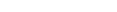
An editor window similar to the example below appears:
The title bar displays Untitled and the type of data area: local data area, global data area or parameter data area (in the example above, Local Data Area). The first row is preset to default values in the cells Level, Name, Format and Length.
In addition, a status bar can appear below the title bar depending on whether the corresponding editor option is set: see Data Area Editor Options in Using Natural Studio.
To invoke the editor for an existing data area
In the Logical View, expand a Local Data Areas subnode to display the data areas available.
Select a data area and choose from the context menu.
Or:
In the command line, enter the following:
EDIT object-name
where object-name is the name of the data area you want to edit.
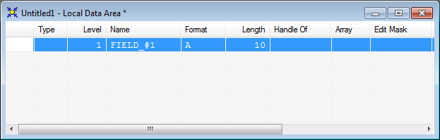
An editor window similar to the example below appears:
The fields contained in the specified data area are read into the editing area of the editor window. The title bar displays the name of the data area (in the example above, LDA-TEST) and the type of data area: local data area, global data area or parameter data area (in the example above, Local Data Area).
For further information on EDIT, see the
relevant section in the System Commands documentation.
The editing area of the editor window is organized in a table where the field definition data is contained in rows and columns. The editor provides a separate row for each field defined for a data area. All attribute definitions that belong to a field are contained in the cells of this row.
The columns and corresponding headings contained in the editor
window are described in the following section. The display of the columns
depends on whether a column is relevant for the type of data area being edited.
For example, the Parent column is only displayed for
global data areas. For explanations of the field attributes mentioned in this
section, see also Field
Definitions in the Programming Guide
and DEFINE DATA in
the Statements documentation. The values used in the
DEFINE DATA statement correspond to the values used for the fields
contained in a data area.
You can resize, move and hide columns as described in Rearranging Columns.
| Column Heading | Explanation | ||||||||||||||||||||||||||||||||||||||||||||||||||||||
|---|---|---|---|---|---|---|---|---|---|---|---|---|---|---|---|---|---|---|---|---|---|---|---|---|---|---|---|---|---|---|---|---|---|---|---|---|---|---|---|---|---|---|---|---|---|---|---|---|---|---|---|---|---|---|---|
| None |
|
||||||||||||||||||||||||||||||||||||||||||||||||||||||
| Type |
|
||||||||||||||||||||||||||||||||||||||||||||||||||||||
| Level | The level of the field.
Levels are used to indicate the structure and grouping of fields. This is relevant to fields of the type view, group, structure and redefinition. Valid level numbers are Level numbers must be specified in consecutive ascending order. A level number can only be one level higher than the previous level. See also the following sections in the Programming Guide: Level Numbers in View Definitions, Level Numbers in Redefinitions and Level Numbers in Group Fields. |
||||||||||||||||||||||||||||||||||||||||||||||||||||||
| Name | The name of the field.
This name corresponds to the field name used in another Natural object (for example, a program) that references this field. For valid names, see the naming conventions for User-Defined Variables and User-Defined Constants in the Programming Guide. Redefine Function: Instead of specifying a variable name, the filler option
( Note: |
||||||||||||||||||||||||||||||||||||||||||||||||||||||
| Format | The Natural data format of an elementary field such as
A (alphanumeric), P (packed numeric) or
L (logical).
For valid Natural data formats, see Format and Length of User-Defined Variables and Special Formats in the Programming Guide. For a counter field ( To modify the format of a field, see also the explanations in Modifying Fields. |
||||||||||||||||||||||||||||||||||||||||||||||||||||||
| Length |
|
||||||||||||||||||||||||||||||||||||||||||||||||||||||
| Handle Of | The type of handle such as a list box. | ||||||||||||||||||||||||||||||||||||||||||||||||||||||
| Array | The array indices.
As an alternative to entering values in the table cell, you can define or modify an array in the Array Definition dialog box as described in Defining Arrays. For further information on how to define an array, see Arrays and Database Arrays in the Programming Guide, and Array Dimension Definition in the Statements documentation. |
||||||||||||||||||||||||||||||||||||||||||||||||||||||
| Edit Mask | Not applicable to parameter data areas.
The edit mask to be used when the field is displayed with an I/O statement. The syntax that applies to specifying an edit mask
corresponds to the syntax of the session parameter
|
||||||||||||||||||||||||||||||||||||||||||||||||||||||
| Header | Not applicable to parameter data areas.
The header to be produced for each field specified in a
The syntax that applies to specifying a header corresponds
to the syntax of the session parameter |
||||||||||||||||||||||||||||||||||||||||||||||||||||||
| Init | Not applicable to parameter data areas.
The initial value assigned to a field. For detailed instructions on how to assign initial values, see Defining Initial Values. For basic information on how to assign initial values, see the sections Initial Values (and the RESET Statement) and Initial Values for Arrays in the Programming Guide. |
||||||||||||||||||||||||||||||||||||||||||||||||||||||
| Comment | A comment which applies to the field.
See also Specifying Comments. |
||||||||||||||||||||||||||||||||||||||||||||||||||||||
| Parent | Not applicable to parameter data areas.
In a global data area: The name of the parent (master) block. If you use a parent block, it must be defined in the current data area. Otherwise, a syntax error occurs. In a local data area: The name of the DDM from which the field derives. |
||||||||||||||||||||||||||||||||||||||||||||||||||||||
| Properties |
|
||||||||||||||||||||||||||||||||||||||||||||||||||||||
| Print Mode | Not applicable to parameter data areas.
The print mode to be used for the field. You can select The print mode is not selected by default indicating that the standard character set is used for printing. |
||||||||||||||||||||||||||||||||||||||||||||||||||||||
You can add a new field to a data area, insert a field, or modify the attributes of a field by using one of the following methods:
Enter each attribute definition into the respective cell of a field row or replace existing definitions.
Enter or replace all attributes in a Definition dialog box by using the appropriate insert function.
Copy fields within a data area, from another data area or from a different type of Natural object by using copy and paste functionality or the import function.
This section below covers the following topics:
Before you perform an editor function, you select (highlight) the row or row cell where you want to create, modify or delete a field.
To select a single field if a cell is selected
Press SHIFT+SPACEBAR.
The field row of the cell is selected.
Or:
Click on the leftmost column of the field row you want to
select.
The specified field row is selected.
To select a single field if a row is selected
Click on the field row you want to select.
Or:
Navigate to the field row you want to select by pressing
UP-ARROW, DOWN-ARROW, HOME or END.
The specified field row is selected.
To select a range of fields if a cell is selected
Press SHIFT+SPACEBAR.
The field row of the cell is selected.
Or:
Click on the leftmost column of the first field row in
the range.
The specified field row is selected.
Hold down SHIFT while you select the row of the last field in the range.
The rows of the specified field range are selected.
To select a range of fields if a row is selected
Click on the leftmost column of the first field row in the range.
Or:
Navigate to the first field row in the range by pressing
UP-ARROW, DOWN-ARROW, HOME or
END.
The first field row in the range is selected.
Hold down SHIFT while you select the row of the last field in the range.
The rows of the specified field range are selected.
To select all fields
From the menu, choose .
Or:
Choose the
 toolbar button.
Or:
Press CTRL+A.
All field rows contained in the current DDM source are selected.
To select a field attribute if a cell is selected
Click on the row cell where you want to add or modify an attribute.
Or:
Navigate to the row cell where you want to add or modify
an attribute by pressing TAB, SHIFT+TAB,
UP-ARROW, DOWN-ARROW, LEFT-ARROW,
RIGHT-ARROW, HOME or END.
The specified row cell is selected.
To select a field attribute if a row is selected
Press F2.
The leftmost cell of the field row is selected.
Or:
First, click on the row that contains the cell you want
to select and then click on the cell where you want to add or modify an
attribute.
The specified row cell is selected.
This section provides instructions for inserting fields into a data area.
Note that you cannot insert a field within a view definition.
To insert a field
Select a single row (multiple rows are not allowed) where you want to place the new field.
The insert position (before or after the selected field) depends on the current setting of:
the toolbar button.
the Insert before/Insert after editor option which is described in Data Area Editor Options in the Using Natural Studio documentation.
Invoke the Definition dialog box by using the insert function that corresponds to the type of field you want to define. The type of field is indicated in the label of the dialog box (for example, Periodic Group Definition).
For explanations of the values to be entered in the Definition dialog box, see Rows and Columns in the Editor Window.
Or:
Copy single or multiple fields into the data area by using
copy and paste functionality (see Copying, Cutting and Pasting
Fields) or the import function (see
Importing
Fields).
Or:
Select a row and press INS, or select a cell in
the last row and press DOWN-ARROW.
A data field with default values for name, data format, length and level is then added.
When you insert a field of the type redefinition, group, periodic group or structure, the level of each subsequent field is automatically incremented properly.
This section provides instructions for modifying single fields (ranges of fields are not allowed) within a data area. You can only modify single fields
Caution:
When changing the field type, all field attribute
definitions may be reset to their default values. This happens, for example,
when you convert a data field to a data structure. You can keep original
attribute definitions by commenting out a field as described in
Specifying
Comments.
Select the row cell that contains the field attribute definition you want to change and either overwrite the existing value or choose a value from a selection box.
Or:
Open the Definition dialog box choosing
one of the following methods:
Double-click on the row that contains the field attribute definition you want to change.
Select the field row that contains the attribute you
want to change and choose the
![]() Modify toolbar button.
Modify toolbar button.
Select the field row that contains the attribute you want to change and choose from the or context menu.
In the Definition dialog box, edit the text boxes and/or select values from the drop-down list boxes as described for the insert function that corresponds to the type of field you want to modify.
For explanations of the values to be entered in a row cell or in the Definition dialog box, see Rows and Columns in the Editor Window.
When you modify the level of a field of the type redefinition, group, periodic group or structure, the level of each subsequent field is automatically incremented or decremented properly, depending on the new level value.
When you modify the Natural data format of a field, the current length is kept if it is also valid for the new data format. Otherwise, the current length specification is automatically replaced by a valid default length (see also the description of the Length column).
When you modify the length of a field that belongs to a
redefinition, consider the following: If the total length of all fields that
belong to the redefinition exceeds the length of the redefined field, the
information sign
![]() or an
appropriate warning message appears.
or an
appropriate warning message appears.
The copy/cut and paste functions of the data area editor are used to copy, move or delete fields within a single data area or between multiple data areas. In addition, you can copy field definitions from a data area into a Natural object that is handled by the program editor (for example, a program). If you want to copy field definitions from another Natural object such as a map and a DDM, use the function described in Importing Fields.
To copy or cut and paste fields
In a data area, select the field(s) you want to copy.
From the or context menu, choose or .
Or:
Choose the or
toolbar button.
Or:
Press CTRL+C (to copy) or CTRL+X (to
cut).
The definitions of the selected fields are placed on the clipboard and can now be pasted into the data area contained in the active editor window.
If you want to paste the fields into another data area, open the appropriate object.
Select the field before or after which (see also insert position) you want to paste the fields.
From the or context menu, choose .
Or:
Choose the toolbar button.
Or:
Press CTRL+V.
The copied or cut fields are pasted at the specified position in the data area contained in the active editor window.
To paste the same fields again, repeat Steps 3 through 5.
When you cut or paste a field of the type redefinition, group, periodic group or structure, the level of each subsequent field is automatically adjusted properly.
This function is used to insert elementary fields that contain scalable definitions.
For explanations of the values to be entered in the dialog box described in the following instructions, see Rows and Columns in the Editor Window.
To insert a data field
Select the row where you want to insert the field (see also insert position).
Select a row and press INS, or select a cell in the last row and press DOWN-ARROW.
A data field with default values for name, data format, length and level is then added.
Or:
From the menu, choose
or press SHIFT+D, or choose
the Insert Data Field toolbar button.
The Data Field Definition dialog box appears.
In the Data Field Definition dialog box, specify the following:
In the Level text box, enter a valid level number.
In the Name text box, enter a valid field name.
From the Format drop-down list box, select the required Natural data format.
Select the Dynamic check box if you want the field length to be set dynamically. In this case, the length text box will be deactivated.
In the Length text box, enter the field length.
In the Edit mask text box, specify an edit mask if you want to use one. This definition does not apply to parameter data areas.
In the Header text box, enter a header if you want to specify one. This definition does not apply to parameter data areas.
In the Comment text box, enter a commentary text if you want to document the field: see Specifying Comments.
- For parameter data areas:
From the Value clause drop-down list box, select any of the following input/output characteristics for the field:
By Reference(this is the default setting),By ValueorBy Value Result.Select the Optional parameter check box if you want to specify the data field as
Optional.For further information, see Properties in Rows and Columns in the Editor Window.
From the Print Mode text box, select the required print mode. This definition does not apply to parameter data areas.
Choose if you want to invoke the Array Definition dialog box where you can define an array: see Defining Arrays.
Choose if you want to invoke the Field Initialization dialog box where you can define an initial value for the field: see Defining Initial Values. This definition does not apply to parameter data areas.
Choose .
The field is inserted into the specified position of the data area. The Data Field Definition dialog box is cleared and remains open.
Choose either of the following options:
Repeat Steps 3 and 4 if you want to define additional fields and insert them into the data area.
Or:
Choose when you are
finished.
The Data Field Definition dialog box is closed.
This function only applies to global data areas.
For explanations of the values to be entered in the dialog box described in the following instructions, see Rows and Columns in the Editor Window.
To insert a data block
Select the row where you want to insert the data block (see also insert position).
From the menu, choose or press SHIFT+B.
Or:
Choose the toolbar
button.
The Block Definition dialog box appears.
In the Block Definition dialog box, specify the following:
In the Name text box, enter a valid name for the data block.
In the Parent text box, enter the name of the parent (master) block. If you use a parent block, it must be defined in the current data area. Otherwise, a syntax error occurs.
In the Comment text box, you can enter a comment that documents the data block: see Specifying Comments.
Choose .
The parent block is inserted into the specified position of
the data area where the Type column indicates
B (for Block), and the Data Field Definition
dialog box appears.
Define the subordinate block(s) that belong to the parent block as described in Inserting Data Fields.
This functions does not apply to parameter data areas.
For explanations of the values to be entered in the dialog box described in the following instructions, see Rows and Columns in the Editor Window.
To insert a constant
Select the row where you want to insert the field (see also insert position).
From the menu, choose or press SHIFT+C.
Or:
Choose the toolbar
button.
The Constant Definition dialog box appears.
In the Constant Definition dialog box, specify the following:
In the Name text box, enter a valid field name.
From the Format drop-down list box, select the required Natural data format.
In the Length text box, enter a field length.
In the Edit mask text box, specify an edit mask if you want to use one. This definition does not apply to parameter data areas.
In the Header text box, enter a header if you want to specify one. This definition does not apply to parameter data areas.
In the Comment text box, enter a commentary text if you want to document the field: see Specifying Comments.
From the Print Mode text box, select the required print mode. This definition does not apply to parameter data areas.
Choose if you want to define an array: see Defining Arrays.
Choose to invoke the Field Initialization dialog box where you can define an initial value for the field: see Defining Initial Values. This definition does not apply to parameter data areas.
Choose .
The field is inserted into the specified position of the
data area where the Type column indicates C
(for Constant) and the Property column indicates
I (for Initialize). The Constant Definition
dialog box is cleared and remains open.
Choose either of the following options:
Repeat Steps 3 and 4 if you want to define additional fields and insert them into the data area.
Or:
Choose when you are
finished.
The Constant Definition dialog box is closed.
For a handle, you can define the type dialog element or object.
For explanations of the values to be entered in the dialog box described in the following instructions, see Rows and Columns in the Editor Window.
To insert a handle
Select the row where you want to insert the field (see also insert position).
From the menu, choose or press SHIFT+H.
Or:
Choose the toolbar
button.
The Handle Definition dialog box appears.
In the Handle Definition dialog box, specify the following:
In the Level text box, enter a valid level number.
In the Name text box, enter a valid field name.
In the Type field, choose either of the following options:
Select the Dialog Element option button for a handle of the type dialog element.
Then from the drop-down list box, select the required dialog element.
Or:
Select the Object option button for a handle of the type object.
The drop-down list box then displays
OBJECT.
In the Comment text box, enter a commentary text if you want to document the field: see Specifying Comments.
- For parameter data areas:
From the Value clause drop-down list box, select any of the following input/output characteristics for the field:
By Reference(this is the default setting),By ValueorBy Value Result.Select the Optional parameter check box if you want to specify the data field as
Optional.For further information, see Properties in Rows and Columns in the Editor Window.
Choose if you want to invoke the Array Definition dialog box where you can define an array: see Defining Arrays.
Choose if you want to invoke the Field Initialization dialog box where you can define an initial value for the field: see Defining Initial Values. This definition does not apply to parameter data areas.
Choose .
The field is inserted into the specified position of the
data area where the Type column indicates H
(for Handle). The Data Field Definition dialog box is
cleared and remains open.
Choose either of the following options:
Repeat Steps 3 and 4 if you want to define additional fields and insert them into the data area.
Or:
Choose when you are
finished.
The Data Field Definition dialog box is closed.
A data structure consists of fields and nested structures.
For explanations of the values to be entered in the dialog box described in the following instructions, see Rows and Columns in the Editor Window.
To insert a data structure
Select the row where you want to insert the data structure (see also insert position).
From the menu, choose or press SHIFT+S.
Or:
Choose the toolbar
button.
The Structure Definition dialog box appears.
In the Structure Definition dialog box, specify the following:
In the Level text box, enter a valid level number.
In the Name text box, enter a valid name for the structure.
In the Comment text box, enter a commentary text if you want to document the data structure: see Specifying Comments.
Choose if you want to invoke the Array Definition dialog box where you can define an array: see Defining Arrays.
Choose .
The data structure is inserted into the specified position
of the data area where the Type column indicates
S (for Structure), and the Data Field
Definition dialog box appears.
Define the subordinate field(s) that belong to the structure as described in Inserting Data Fields.
This function only applies to local data areas and global data areas.
For explanations of the values to be entered in the dialog box described in the following instructions, see Rows and Columns in the Editor Window.
To insert a Globally Unique Identifier
Select the row where you want to insert the field (see also insert position).
From the menu, choose or press SHIFT+U.
Or:
Choose the toolbar
button.
The Globally Unique ID Definition dialog box appears.
In the Globally Unique ID Definition dialog box, specify the following:
In the Level text box, enter a level number.
In the Name text box, enter a valid field name.
In the Comment text box, enter a commentary text if you want to document the field: see Specifying Comments.
Choose .
The field is inserted into the specified position of the
data area as a Natural constant with length A36. The Type
column for the field row indicates U (for Globally Unique
Identifier) and the Init column displays the contents of
the constant (for example, CONST
<'2AEB9D1A-EAC2-4E5E-8983-0AF0CCB12098'>). The Globally
Unique ID Definition dialog box is cleared and remains
open.
Choose either of the following options:
Repeat Steps 3 and 4 if you want to define additional fields and insert them into the data area.
Or:
Choose when you are
finished.
The Global Unique ID Definition dialog box is closed.
The Array Definition dialog box can be used to define multi-dimensional tables for the field name and field type indicated in the box.
For detailed information on how to define an array, see Arrays and Database Arrays in the Programming Guide, and Array Dimension Definition in the Statements documentation.
To define an array in the Array Definition dialog box
From the Definition dialog box, choose .
The Array Definition dialog box appears for the specified field name and type.
In the Array Definition dialog box, specify the following:
From the Dimensions drop-down list box,
select the number of dimensions for the array: 1, 2,
or 3. To delete an array definition, select 0
(zero).
In the Lower bound text box, enter the lower bound for each dimension.
In the Upper bound text box, enter the upper bound for each dimension.
Choose .
The definitions are saved, the Array Definition dialog box is closed and the Data Field Definition dialog box appears.
An X-array (eXtensible array) can be defined by specifying an
asterisk (*) for at least one bound of at least one dimension of
the array. The asterisk (*) in the bound definition indicates that
the corresponding bound is extensible. Only one bound - either upper or lower -
may be extensible, but not both. If the lower bound is extensible, the
Upper bound text box contains the upper bounds of the
X-array.
For more information on defining an X-array, see X-Arrays in the Programming Guide and Array Dimension Definition in the Statements documentation.
This definition does not apply to parameter data areas.
The Field Initialization dialog box is used to assign an initial value to a field. For further information on how to assign initial values, see the sections Initial Values (and the RESET Statement) and Initial Values for Arrays in the Programming Guide.
In the Field Initialization dialog box, you can enter the value(s) for a data field in two different ways: single-value mode or free-form mode.
In single-value mode, you enter the values in a structured way.
Parentheses, apostrophes or value prefixes (for example, H for
Hex, D for Date, or T for Time) are not required.
In free-form mode, you enter the values just as you would in a
DEFINE DATA statement; see also
Initial-Value
Definition and Initial/Constant Values for an
Array in the Statements
documentation.
To define an initial value in single-value mode
From the Definition dialog box, choose .
Or:
Select the row cell of the Init column
which contains the initial value required and choose the following button:
![]() This button is only available for a field that has been defined as an
array.
This button is only available for a field that has been defined as an
array.
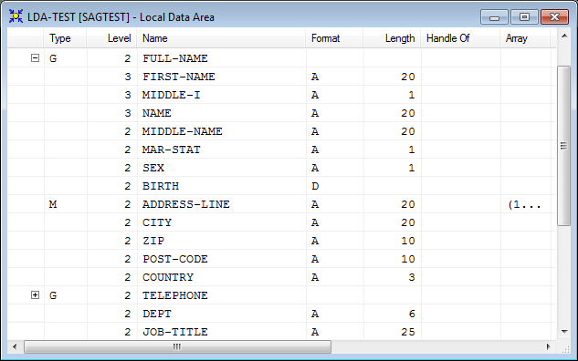
The Field Initialization dialog box appears with the tabbed pages Single-Value Mode and Free-Form Mode. The Single-Value Mode page is opened by default. It contains a table similar to the example shown below:
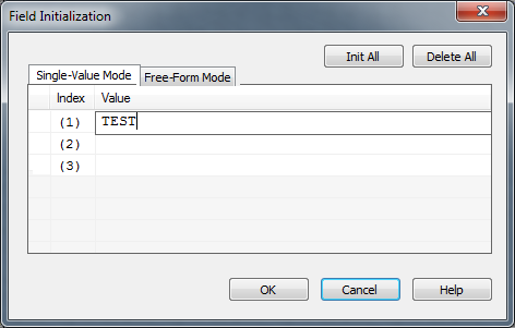
The indicator column in the leftmost section contains error information if an incorrect value is entered in the Value column.
For a field that has been defined as an array, the
Index column is displayed, which lists all occurrences of
the array as shown in the example above for an array defined as
(1:2,1:3).
The Value column contains the initial value if assigned to the field (scalar) or array occurrence.
You can use TAB, CR or DOWN ARROW to go down one row in the table, and SHIFT+TAB or UP ARROW to go up one row. When you resize a column or select a row, press F2 to deselect the row and go to the Value column.
For a field that has been defined as a scalar, enter an initial value or replace the existing entry in the Value column, skip the following step and proceed with Step 4.
For a field that has been defined as an array, proceed with the following step.
In the Value column next to the Index row cell that contains the required array occurrence, add an initial value or replace the existing entry.
Or:
To assign an initial value to all occurrences,
enter the required initial value for one of these occurrences, keep the cursor
inside this row cell, and choose the button.
The initial value entered is then assigned to all occurrences.
Or:
To remove the initial values assigned to all
occurrences, choose the button. The initial
values entered are then removed from all occurrences.
The initial value is checked when you leave the row cell and continue editing another field definition, or when you choose in the Field Initialization dialog box.
The definitions on the Single-Value Mode page are checked and saved, and the Field Initialization dialog box closes.
To define an initial value in free-form mode
From the Definition dialog box, choose .
Or:
Select the row cell of the Init column
which contains the initial value required and choose the following button:
![]() .
This button is only available for a field that been defined as an array, or for
a value definition that spans multiple lines.
.
This button is only available for a field that been defined as an array, or for
a value definition that spans multiple lines.
The Field Initialization dialog box appears with the tabbed pages Single-Value Mode and Free-Form Mode.
Open the Free-Form Mode page.
An edit box appears. If no initial value yet exists, the
box is preset to a value such as INIT (1) <…>
.
Enter the initial value definitions according to the common
syntax definitions in a DEFINE
DATA statement (see the Statements
documentation).
Choose .
The definitions on the Free-Form Mode page are saved and the Field Initialization dialog box closes. The definitions are validated when you check or stow the data area with the appropriate menu function or system command.
For explanations of the values to be entered in the dialog box described in the following instructions, see Rows and Columns in the Editor Window.
To define a counter field
Select the multiple field or periodic field you want to
define as a counter field (C* variable).
From the menu, choose or press SHIFT+C.
Or:
Choose the toolbar
button.
A 'C*' Counter Definition dialog box appears for the specified field.
In the 'C*' Counter Definition dialog box, specify the following:
In the Level text box, change the field level if required.
From the Format drop-down list box, select the required format.
In the Length text box, enter a valid field length.
In the Comment text box, enter a commentary text if you want to document the counter field: see Specifying Comments.
Choose .
The 'C*' Counter Definition dialog box
is closed and the Type column now indicates C
(for counter).
You can import single or multiple fields into a data area from different Natural object types in any library or from a Predict server.
To import fields from another type of Natural object
Select the row where you want to insert the fields (see also insert position).
From the menu, choose or press SHIFT+O.
Or:
Choose the toolbar
button.
The Import Data Field dialog box appears. The name of the current library is displayed in the Library list box.
In the Import Data Field dialog box, specify the following:
From the Library list box, select another library if the object that contains the fields you want to import is located in a different library.
The list contains all libraries that reside in the current FNAT and FUSER system file, which are displayed as nodes in the Natural Studio tree view (the display can be limited by using the Display Filter function of Natural Studio). In addition, the list contains all libraries from inactive system files as specified in the steplib table.
From the Type group frame, select the option button that corresponds to the type of Natural object from which you want to import fields.
Or:
Depending on the type of Natural object required, use one of the following shortcut keys:
| ALT+P for program | ALT+M for map |
| ALT+N for subprogram | ALT+L for local data area |
| ALT+7 for function | ALT+G for global data area |
| ALT+S for subroutine | ALT+A for parameter data area |
| ALT+H for helproutine | ALT+V for DDM |
The Object List list box appears with a list of all Natural objects of the specified object type available in the selected library.
The list contains all objects, which are displayed in the library nodes of the Natural Studio tree view (the display can be limited by using the Display Filter function of Natural Studio).
For DDMs and data areas, the list only contains objects for which both a source object and a cataloged object exist.
From the Object List list box, select the object that contains the fields you want to import.
The fields contained in the selected object appear in the Importable Data Fields list box.
From the Importable Data Fields list box, select one or more fields that you want to import.
Choose or double-click on a field.
For fields from a DDM, the View Definition dialog box appears where the name of the DDM is displayed in the Name of DDM text box.
In the Name of View text box, enter the name to be used for the view in the data area.
In the Comment text box, enter a commentary text if you want to document the view: see Specifying Comments.
Choose when you are finished.
If you import a multiple-value field from a DDM, the Array Definition dialog box appears.
In the Lower bound and Upper bound text boxes change the values if required.
The Array Definition dialog box does not appear if you import a multiple-value field from a view definition in a local or a global data area. The number of occurrences is then automatically copied from the selected field into the array definition.
Choose when you are finished.
If you import one or more fields that belong to a periodic group, the Periodic Group Definition dialog box appears.
Select either of the following option buttons: PE group or Each field in PE group (this is the default setting).
If you select PE group, the Lower bound and Upper bound text boxes appear where you can change the values if required.
The Periodic Group Definition dialog does not appear if you import fields of a periodic group from a view definition in a local or a global data area. The number of occurrences is then automatically copied from the selected fields into the array definition.
Choose when you are finished.
The fields are copied into the current data area and the Import Data Field dialog box remains open.
Repeat Steps 3 and 4 if you want to import additional fields.
Choose when you are finished.
The Import Data Field dialog box is closed.
You can exclude fields from the syntax check by marking or unmarking the corresponding rows. In addition, you can insert commentary rows or add commentary text to an existing field. You can also add a comment and insert a commentary row with the function described in Redefining Fields.
To convert single or multiple fields to commentary rows
Select the required field row or the range of field rows.
Choose one of the following methods:
From the menu, choose either > or > Remove Comment Mark(s).
Or:
Press CTRL+M to comment out the field or CTRL+SHIFT+M to remove the comment mark.
Or:
From the drop-down list box in the Type cell of the required field row, select * to comment out the field, or select the appropriate field type value if you want to remove the comment mark, and choose ENTER.
A comment mark (*) in the
Type cell of the selected field row indicates that the
field has been converted to a commentary row. All field attribute definitions
in the row cells are retained.
An empty Type cell or another field
type value other than * indicates that the comment mark has been
removed from the selected field row.
To convert a field to an empty commentary row
From the drop-down list box in the Type cell of the field row to be marked, select /* and choose ENTER.
A comment mark (*) appears in the
Type cell of the field row and all row cells are
cleared.
To insert a commentary row
Select the field row above or below which (see also insert position) you want to insert the commentary row.
From the menu, choose or press SHIFT+M.
Or:
Choose the toolbar
button.
The Comment Line Definition dialog box appears.
In the Comment text box, enter any text.
Choose .
The commentary row is inserted into the specified position of the data area and the Comment text box is cleared and remains open.
Choose either of the following options:
Repeat Steps 3 and 4 if you want to insert additional commentary rows into the data area.
Or:
Choose when you are
finished.
The Comment Line Definition dialog box is closed.
To add a comment to a field
In the Comment column of the field you want to document, enter any text.
Or:
Open the Definition dialog box and
enter any text in the Comment text box.
You can search for field names and comments contained in the current data area by using the find function. If it should be necessary to replace a frequently occurring text string, you can use the combined find and replace function.
The find function is performed on all data definitions including collapsed blocks of fields (see also Showing or Hiding Fields).
Caution:
There is no undo function available to restore original
names.
To search for a text string
From the menu, choose .
Or:
Choose the  toolbar button.
Or:
Press CTRL+F.
The Find dialog box appears.
In the Find text box, enter a search string.
Select the Name check box if you want to restrict the search to the field names contained in the Name column.
Select the Comment check box if you want to restrict the search to the commentary text contained in the Comment column.
Select the Case sensitive check box to search for strings that exactly match the entry in the Find text box. Otherwise, any combination of upper and lower-case letters will be found. This option only applies to commentary text contained in the Name or Comment column.
Select the Whole words only check box to restrict the search to whole words only. Otherwise, all occurrences of the search string will be found.
In the Direction section, select the option button Up or Down to specify whether the search is to be performed from the cursor position to the end of the data area or from the cursor position to the beginning of the data area. The default setting is Down.
Choose .
If no instance of the search string is found, an appropriate message is displayed.
If an instance of the search string is found, it will be selected.
To search for additional instances of the search string: from the menu, choose .
Or:
Choose the toolbar
button.
Or:
Press F3.
To replace a text string
From the menu, choose .
Or:
Choose the toolbar
button.
Or:
Press CTRL+H.
The Replace dialog box appears.
In the Find text box, enter a search string.
In the Replace with text box, enter a replacement string.
Select the Name check box if you want to restrict the search to the field names contained in the Name column.
Select the Comment check box if you want to restrict the search to the commentary text contained in the Comment column.
Select the Case sensitive check box to search for text strings that exactly match the entry in the Find text box. Otherwise, any combination of upper and lower-case letters will be found. This option only applies to commentary text contained in the Name or Comment column.
Select the Whole words only check box to restrict the search to whole words. Otherwise, all occurrences of the search string will be found.
In the Direction section, select the option button Up or Down to specify whether the search is to be performed from the cursor position to the end of the data area or from the cursor position to the beginning of the data area. The default setting is Down.
Choose to replace the next hit found in the source.
Choose and to find the next hit and replace it.
Or:
Choose the and
toolbar buttons.
Or:
Choose to replace the
next hit found without selecting the hit first.
Or:
Choose to replace all
search strings found.
If no instance of the search string is found, an appropriate message is displayed.
Choose to exit the dialog box.
This function does not apply to a field in a view defined in a parameter data area.
When redefining a field, you can convert the Natural data format
of a field or divide a single field into data segments. For details, see the
redefinition option of the
DEFINE
                                                DATA
statement in the Statements
documentation.
To redefine a field definition from one type to another
Select the field you want to redefine.
From the menu or context menu, choose or press SHIFT+E.
Or:
Choose the toolbar
button.
A new row is inserted into the data area which contains the
same name and level as the selected field and a BEGIN REDEFINE
comment. In addition, the Insert Redefine dialog box
appears.
In the Insert Redefine dialog box, select any of the following option buttons:
Structure to define a structure.
Or:
Data field to define an elementary field.
Or:
Comment to add a commentary line that documents the redefinition (see also Specifying Comments).
Choose .
Depending on the option set, a corresponding dialog box appears for the specified field: Structure Definition, Redefine or Comment Line Definition.
Enter the required values as described in Inserting Data Fields, Inserting Data Structures or Specifying Comments respectively.
Note:
In the Name text box of
the Redefine dialog box, you can enter
nX to specify filler bytes.
Choose .
The field is inserted into the data area and the Insert Redefine dialog box appears again.
Repeat Steps 3 through 6 until no more space is available or until the redefinition is complete.
If the total length of all fields that belong to the redefinition
exceeds the length of the redefined field, the information sign
![]() or an
appropriate warning message appears.
or an
appropriate warning message appears.
This section provides instructions for deleting fields in a data area.
To delete fields in the data area editor
Select the field(s) to be deleted.
From the or context menu, choose .
Or:
Press DEL.
Or:
Choose the toolbar button.
Or:
Press CTRL+X.
If delete messages are active, you are requested to confirm the deletion. Otherwise, the fields are deleted without prior warning.
When you delete a field of the type redefinition, group, periodic group or structure, the level of each subsequent field is automatically decremented properly.
In the editor window, you can adjust the display of the data area to your needs by resizing, moving or hiding columns that are not required for an editing operation in the current data area.
You can automatically adjust a single column or all columns to the best size, or change the width of a single column to a specific size.
To resize all columns to best fit
Choose one of the following methods:
Select a field as described in Selecting Single Fields.
Or:
In any column heading, click the right
mouse button and choose from the
context menu.
The Customize Columns dialog box appears.
Select the Best Fit check box. This option is not selected by default.
All columns in the active editor window are automatically resized to the size that best fits into the editor window whereby the column headings always remain visible.
Or:
Press CTRL+PLUS.
Or:
If you want to apply Best Fit to all
active editor windows, set the corresponding editor option described in
Data Area
Editor Options in the Using Natural
Studio documentation.
To resize all columns to best fit while typing in text
Open the Customize Columns dialog box as described in To resize all columns to best fit.
Select the Best Fit check box and, additionally, select the Auto Fit check box.
Each column in the active editor window is then automatically adjusted to fit the text you type in a row cell or a Definition dialog box when you leave the column or dialog box respectively.
Or:
If you want to apply Best Fit and
Auto Fit to all active editor windows, set the
corresponding editor options described in
Data Area
Editor Options in the Using Natural
Studio documentation.
To resize a single column to fit the contents
In the heading of the column you want to change, place the pointer over the right border. When the pointer changes to a divider, double-click on the border between the column headings. Note that you cannot resize the leftmost column.
The column is automatically adjusted to fit its contents.
To resize a single column to a specific size
In the heading of the column you want to change, place the pointer over the right border. When the pointer changes to a divider, drag the divider to the width you require. Note that you cannot resize the leftmost column.
The width of the column has changed to the specified size.
To save a resized table
layout
Open the Customize Columns dialog box as described in To resize all columns to best fit and choose one of the following buttons.
saves the new table layout for the current editor session.
saves the new layout in your user profile and retains it for future editor sessions.
overwrites the current layout with the layout previously saved in the user profile. Choose to save this layout.
followed by overwrites the layout saved in the user profile with the default layout initially provided by the editor. Choose to save this layout.
Or:
In the editing area of the editor window, press
CTRL+ALT+L.
The new layout is saved in your user profile and retained for future editor sessions.
You can change the table layout by moving single or multiple columns.
To move a column
Choose one of the following methods:
Select a field as described in Selecting Single Fields.
Open the Customize Columns dialog box as described in To resize all columns to best fit.
From the Displayed Columns list box, select the columns you want to move and choose or (if required repeatedly) until the columns have reached the target position.
The top-to-bottom order of the list box corresponds to the left-to-right of the table in the editor window, that is, the top list column corresponds to the leftmost table column.
Or:
Drag the column heading you want to move and drop it in the position required. Note that you cannot move the leftmost column.
Open the Customize Columns dialog box as described in To resize all columns to best fit.
To keep the new table layout, proceed as described in To save a resized table layout.
You can change the table layout by hiding or displaying columns.
To hide a column by rearranging the display order
Select a field as described in Selecting Single Fields.
Open the Customize Columns dialog box as described in To resize all columns to best fit.
From the Displayed Columns list box, select the columns you want to hide.
The top-to-bottom order of the list box corresponds to the left-to-right of the table in the editor window, that is, the top list column corresponds to the leftmost table column.
Note:
You cannot select Type,
Level, Name,
Format and Length which are mandatory
for the table layout.
Choose .
The selected columns are removed from Displayed Columns and appear in the Hidden Columns list box.
To keep the new table layout, proceed as described in To save a resized table layout.
To hide a column by moving column borders
In the heading of the column you want to hide, place the pointer over the right border. When the pointer changes to a divider, drag the divider to the left border until the column heading is completely invisible (right and left border lines must coincide).
Note:
You cannot hide the columns Type,
Level, Name,
Format and Length which are mandatory
for the table layout.
The hidden column then appears in the Hidden Columns list box of the Customize Columns dialog box.
To keep the new table layout, proceed as described in To save a resized table layout.
To display a hidden column
Select a field as described in Selecting Single Fields.
Open the Customize Columns dialog box as described in To resize all columns to best fit.
From the Hidden Columns list box, select the columns you want to display in the editor window.
Choose .
The selected columns are removed from Hidden Columns and appear in the Displayed Columns list box.
To keep the new table layout, proceed as described in To save a resized table layout.
You can show (expand) or hide (collapse) blocks of fields to improve readability and maintainability of data areas with complex data structures. When a block of fields is collapsed, all fields contained in this block are hidden, including any other nested blocks if they are part of the chosen block. Hidden blocks retain their collapsed or expanded state.
Blocks that can be expanded or collapsed are blocks of fields that are defined for the same field level (1 to 99). Blocks are expanded or collapsed by the hierarchy of levels, from highest level 1 to lowest level 99. A block that contains fields from a lower-ranking level is contained in a block from a higher level.
When scanning fields (see also Finding and Replacing Field Names), collapsed blocks are also scanned.
If you want to expand and collapse blocks of fields, you need to set the appropriate editor option referenced in the instructions below.
To expand and collapse single blocks
Set the Expand/Collapse editor option as described in Data Area Editor Options in the Using Natural Studio documentation.
When the Expand/Collapse option is set,
an expand/collapse toggle (![]() or
or
![]() )
appears as shown in the example of an
editor window shown
earlier.
)
appears as shown in the example of an
editor window shown
earlier.
The toggle
![]() indicates the first row of an expanded block.
indicates the first row of an expanded block.
The toggle
![]() indicates the first row of a collapsed block.
indicates the first row of a collapsed block.
Click on the toggle
![]() to
expand a block or click on the toggle
to
expand a block or click on the toggle
![]() to collapse a block.
to collapse a block.
Or:
Position the cursor in a row that contains the toggle
![]() or
or
![]() and, from the menu, choose
or choose the
and, from the menu, choose
or choose the
![]() toolbar button.
toolbar button.
Or:
Use any of the shortcut keys listed in
Data Area
Editor Shortcut Keys in the Using Natural
Studio documentation.
To expand or collapse all blocks
From the menu, choose or .
Or:
Choose the
![]() or the
or the
![]() toolbar button.
toolbar button.
You can navigate through the level hierarchy of fields contained in a data area.
To navigate to the next lower field level
From the menu, choose .
Or:
Press CTRL+SHIFT+I.
Or:
Choose the toolbar
button.
The first field with a lower level is selected.
To navigate to the next higher field level
From the menu, choose .
Or:
Press CTRL+SHIFT+J.
Or:
Choose the toolbar
button.
The first field with a higher level is selected.
You can save source code of a data area as a source object and/or a cataloged object (generated program) in the current Natural library in the current Natural system file.
For the naming conventions that apply to an object, refer to Object Naming Conventions in the Using Natural Studio documentation.
To save source code as a source object
Proceed as described in Saving Objects in the Using Natural Studio documentation.
To save source code as a source object and/or a cataloged
object
Proceed as described in either Stowing Objects or Cataloging Objects in the Using Natural Studio documentation.
This function generates a Natural object of the type copycode from a
data area. The DEFINE DATA statement in the copycode then contains
the data definitions from the current data area. You can then edit the
generated copycode with the program editor.
To generate copycode
Open the data area from which you want to generate copycode.
From the menu, choose or press SHIFT+G.
An Untitled - Copycode window appears that contains the source code of the data area.
Save the copycode as a source object as described in Saving Objects in the Using Natural Studio documentation.