
Natural for DL/I operates as a standard DL/I application.
Prior to running a Natural application, a PSB must be scheduled. The method for scheduling PSBs varies depending on the actual environment (see the relevant sections under PSB Scheduling), but as for any other DL/I application, PSB scheduling is a requirement.
This section covers the following topics:
Every PSB required by DL/I to accommodate Natural requests must be
processed by the Natural batch utility NDPBNSB0. This utility
stores DL/I PSB information, in a form suitable for Natural, on the
FDIC system file. This information is referred to as NSB control
block. A batch procedure called NATPSB has been established for
this purpose.
A sample NATPSB job has been included in the source library
from the installation medium. The information used to create NSB control blocks
comes from the actual PSBGEN source. It is essential that the same input is
used for the NATPSB procedure as was used for the DL/I PSBGEN.
Otherwise, unpredictable results are likely.
The NATPSB job is a three step procedure:
The first step executes the normal DL/I PSBGEN procedure. This step is included to guarantee compatibility between DL/I and Natural.
The second step performs another assembly and link of the PSBGEN source, this time using macros supplied by Natural.
The final step executes the Natural batch utility
NDPBNSB0, which uses the linked PSB module from the previous step
to create NSB control blocks which are stored on the FDIC system
file. NDPBNSB0 dynamically loads the Natural module
NDLB0002, which therefore must be present in an allocated load
library.
Natural requires one or more PSBs for batch and/or online processing. Depending on application requirements, the PSB can be switched during a Natural session. Each PSB describes all user views that can be used to access DL/I databases from Natural programs if this PSB is active. A PSB must contain one or more program communication blocks (PCBs) for each DBD to be accessed. Since Natural only uses the single positioning option on PCBs, Natural programs that maintain two or more independent positions in a database require a PCB (of the appropriate type) for each separate position.
If this requirement is not fulfilled, Natural for DL/I issues the runtime error message:
NAT3789 Active PSB contains too few PCBs for program execution
The PCB in use must have segment sensitivity and the appropriate
PROCOPT parameter specified for Natural, to be able to
perform a segment update.
Nested I/O loops (FIND or READ) in Natural
programs frequently require separate positions in the same database to be
maintained. To reduce the number of PCBs needed, as many I/O loops as possible
should be closed before opening subsequent I/O loops.
Consider the following sample DL/I database:
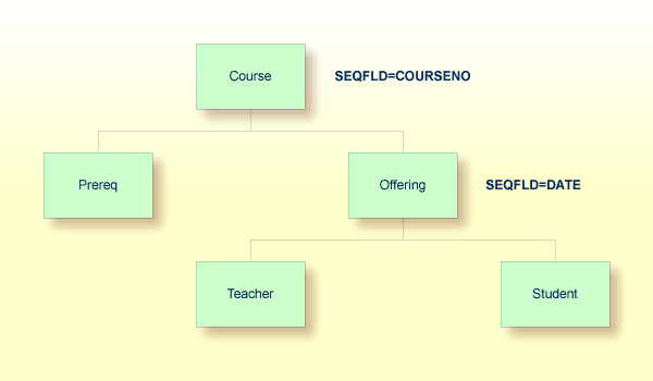
The following Natural program based on the above database requires two PCBs:
READ ED00DBD-COURSE BY COURSENO
   FIND ED00DBD-PREREQ WITH COURSENO-COURSE = COURSENO
     FIND ED00DBD-OFFERING WITH COURSENO-COURSE = COURSENO
     LOOP
   LOOP
LOOP
END
The first PCB is used to maintain position on the COURSE
and PREREQ segments. A second PCB is required for the
OFFERING segment since the FIND loop has not been
terminated for the PREREQ segment prior to invoking a
FIND on the OFFERING segment. By closing the first
FIND loop prior to opening the second one, this program would only
require one PCB.
Natural selects the PCB to be used for a database request in the following manner:
Natural selects the first PCB in the PSB with the correct DBD name and
the appropriate PROCSEQ parameter (if applicable).
Natural then determines if the PCB can be used for the request or if there is a conflict due to current database positioning.
If there was a positioning conflict or the PCB did not contain the
correct DBD name or PROCSEQ parameter, Natural would
continue scanning the PSB.
If the database search request refers to a secondary index, Natural
attempts to use a PCB with the corresponding PROCSEQ
parameter. If there is no PCB of this type in the PSB, Natural tries to use a
PCB without the PROCSEQ parameter. In this case, it is
assumed that the INDICES parameter has been coded in the
appropriate SENSEQ statement.
If no eligible PCB could be found, an error message would be generated.
In general, PCBs for use by Natural can have different
PROCOPT parameters. However, if there are two or more
PCBs in the PSB referring to the same DBD, these PCBs must appear consecutively
in the PSB source and they must specify the same SENSEG statements
and same PROCOPT parameters. They can, however, have
different PROCSEQ parameters.
When locating an eligible PCB, Natural disregards the
PROCOPT parameter of the PCB. The first free PCB is
selected independently of the PROCOPT parameter, so that
if the chosen PCB has a PROCOPT that does not support
the request, an error message that corresponds to a DL/I status code is
returned.
Natural assumes that all PCBs with the same DBD name and the same
PROCSEQ parameter contain the same SENSEG
statements as the first PCB. If this is not true and a PCB is selected that
does not contain a SENSEG statement for the segment being
referenced, an error message that corresponds to a DL/I status code is
returned.
The following example PSB and Natural program demonstrate that the
sequence of the PCBs, referring to the same DBD, may affect Natural programs if
the PROCOPT parameters are different:
PCB    TYPE=DB,DBDNAME=ED00DBD,PROCOPT=GO,...
SENSEG NAME=COURSE
SENSEG NAME=OFFERING,PARENT=COURSE
PCB    TYPE=DB,DBDNAME=ED00DBD,PROCOPT=A,...
SENSEG NAME=COURSE
The following program requires two PCBs: the first PCB is used for the
READ loop (which reads all COURSE segments) and the
second nested FIND loop (which finds one offering to a given
course); the second PCB is used for the first FIND loop (which
updates a specific COURSE segment). The program does not work if
the order of the two PCBs is reversed.
READ COURSE BY COURSENO
   FIND (1) COURSE WITH COURSENO = '120'
      UPDATE WITH TITLE = 'Natural'
   LOOP
   FIND (1) OFFERING WITH COURSENO-COURSE = COURSENO (0010)
      DISPLAY COURSENO-COURSE
   LOOP
LOOP
END
The following figure shows the logical connections between DL/I PSBs, PCBs, sensitive segment types and Natural DDMs:
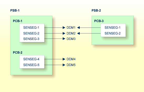
Natural DDMs which are derived from segment descriptions in the DBD correspond to DL/I segment types.
Since each DL/I application program requires the specification of its sensitive segment types, an appropriate PSB must be scheduled before Natural program execution. A PSB can be scheduled at the start of a Natural session or at any time during the session.
If, in the configuration shown in the diagram above, PSB-2 has been scheduled, only the DDMs DDM1 and DDM2 are accessible to Natural application programs. If an attempt is made to use DDM5, for example, Natural for DL/I returns the error message:
NAT3768 PCB with requested DBD not found in NSB
Every DL/I database structure, both physical and logical, which is
supposed to be used by Natural, must be processed by the Natural batch utility
NDPBNDB0.
This utility stores DL/I database information on the FDIC
system file, in a form suitable for Natural. This information is referred to as
NDB control block. A batch procedure called
NATDBD has been established for this purpose.
A sample NATDBD job has been included in the source library
on the installation medium. The information used to create NDB control blocks
comes from the actual DBDGEN source. It is essential that the same input is
used for the NATDBD procedure as was used for the DL/I DBDGEN.
Otherwise, unpredictable results are likely.
The NATDBD job is a three step procedure:
The first step executes the normal DL/I DBDGEN procedure. This step is included to guarantee compatibility between DL/I and Natural.
The second step performs another assembly and link of the DBDGEN source, this time using macros supplied by Natural.
The final step executes the Natural batch utility
NDPBNDB0, which uses the linked DBD module from the previous step
to create NDB control blocks which are stored on the FDIC system
file. NDPBNDB0 dynamically loads the Natural module
NDLB0001, which therefore must be present in an allocated load
library.
The NATDBD procedure assigns a short name of two bytes to
each DL/I field; that is, to each field defined in the DBD. All field short
names are generated in the range from NA to Z9, which
means that up to 13 * (26 + 10) = 468 DL/I fields can be managed per DBD. DL/I
short names are generated uniquely within an NDB.
When replacing an NDB, NATDBD reassigns short names in a
consistent way; that is, the same short name to the same field name. In
addition, the UDFs are maintained, where the new NDB contains the new DL/I
layout followed by the old UDF layout, which means that UDFs are not deleted by
NATDBD. It is the administrator's responsibility to edit the
segment description after NATDBD has been executed, in order to
modify the UDFs accordingly.
The following information must be considered when using logical databases with Natural:
Execute the NATDBD procedure for a logical database only
after successful execution of the procedure for the physical databases referred
to. In other words, if the input DBD is a "logical" DBD, the NDBs
generated from the "physical" DBDs must already be stored in the
Natural FDIC system file to correctly generate the NDB control
blocks related to this segment.
When a segment specifying the
SOURCE=keyword is processed by the
NATDBD procedure, the related "physical" DBD must
already be stored in the Natural FDIC system file.
If the SOURCE=keyword is
specified (in one or more segments) in a "physical" DBD, which
means that one or more logical virtual child segments are involved (recursively
or not), the NATDBD procedure run against this DBD stores the NDB structure on
the Natural FDIC system file even if one or more physical DBDs referred to by
the SOURCE=keyword specifications have
not already been stored.
In this case, the logical virtual child segments whose source DBD is not yet in the Natural FDIC system file as well as their descendants are not accessible to the user since Natural has marked these segments as inhibited. An appropriate Natural error message is issued indicating the name(s) of the related physical DBD(s) that need to be stored into the Natural system file.
If the logical relationship is the result of a recursive database
structure, the NATDBD procedure for the physical DBD must be run
at least twice: the first time, the NDB is stored on the Natural system file
with the undefined segment marked as inhibited; the second time, the reference
to the SOURCE segment is resolved.
If multiple physical databases are logically related, the
NATDBD procedure must be run for each of these physical databases
and then rerun for any database that contained logical child segments marked as
inhibited.
If the SOURCE=keyword is
specified in a "logical" DBD and one or more source DBDs are not
found in the Natural FDIC system file while running the
NATDBD procedure, the NDB structure is not stored and an
appropriate error message is returned.
If an attempt is made to generate a DDM for a segment whose NDB
control blocks are not in the Natural FDIC system file, a Natural
error message is returned.
The following information must be considered when using index databases with Natural:
To access a secondary index database as data, the secondary index database must be defined as an independent physical database to both DL/I and Natural.
The NATDBD procedure need not be executed for primary or secondary index DBDs.
The DBDGEN source usually does not define all fields within a segment.
Additional segment fields called User-Defined Fields (UDFs) can be entered as
part of creating the DDMs. UDFs define the additional data in the segment that
can be referenced by a Natural program. UDFs can be generated online using
Predict or the Natural SYSDDM
Utility, or they can be generated in batch mode using the
NATUDF procedure.
The NATUDF procedure invokes the batch utility
NDPBCUDF, which stores segment description layout information on
an FDIC system file.
Important:
Before NDPBCUDF can be executed, the DL/I DBD must
have been stored as an NDB on the FDIC system file, and a DBID and
FNR must have been assigned (with Predict or SYSDDM) to each
segment concerned. Otherwise, NDPBCUDF cannot read the segments
concerned.
The input for this utility is provided by the segment description read from a work file. This work file contains segment identification statements and segment field descriptions.
You can format data by using either delimiter mode (IM=D)
or forms mode (IM=F); see also the IM profile parameter in
the Natural Parameter Reference documentation. In
delimiter mode, the delimiter character can be used. In forms mode (for
example, if input is passed from other programs), input data fields are assumed
to be in contiguous storage and must be filled up to the internally defined
full length.
One line is required for the segment identification statement, and two lines are required for each segment field description.
The section below covers the following topics:
One line has to be supplied for each segment being defined. The following syntax is used (the parameters must be specified in the sequence shown below):
FUNC=(function),DBD=dbd-name,SEGM=segment-name
function
|
Function to be applied to the segment:
|
||||||||
dbd-name
|
A 1 to 8 character alphanumeric DBD name; that is, the name of the DL/I DBD which owns the segment to be defined. | ||||||||
segment-name
|
A 1 to 8 character alphanumeric name of the DL/I segment to be defined. |
The segment identification statement has to be followed by at least one segment field description. The following syntax is used for each field to be defined (the parameters must be specified in the sequence shown below):
FUNC=FLD,NAME=fnam,TYPE=type,LEVEL=lev,LENGTH=lgh,MAXOCC=moc,VAR=var
FUNC=STR,BEGIN=begin
After each FLD card, a STR card must be coded, except for the last FLD
card, which is specified with four dollar signs ($$$$) in the
field name. After this last FLD card, an END card must be coded.
fnam
|
The name of the field being defined. This must be an
alphanumeric value of 1 to 19 bytes. The value $$$$ closes the
definition of the current segment.
|
||||
type
|
The UDF field format (1 character). The following formats can be specified: A, B, F, P, U, N, S. | ||||
lev
|
The field level (1 digit). | ||||
lgh
|
The field length (4 digits). | ||||
moc
|
The maximum occurrence (3 digits) of the field (only applicable for a multiple-value field or a periodic group). | ||||
var
|
Possible values:
|
||||
begin
|
The starting position of the field being redefined. This can be specified either in terms of bytes relative to the beginning of the segment or as a field name of the DL/I field being redefined. The value must be alphanumeric and 1 to 19 characters long (32 bytes in forms mode, as the field is 32 characters long in this mode). |
The short name is automatically assigned by the utility in the range
from AA to G9, excluding EA to
E9. The range from HA to M9 is reserved
for UDFs of logical child segments. Thus, up to 216 fields can be provided as
input, which is the maximum number of UDF fields.
For further information on UDF field parameters, please refer to DL/I Services.
FUNC=REP,DBD=ED02DBD,SEGM=COURSE
FUNC=FLD,NAME=GENG1,TYPE=N,LEVEL=1,LENGTH=5
FUNC=STR,BEGIN=11
FUNC=FLD,NAME=DUM1,TYPE=A,LEVEL=1,LENGTH=6
FUNC=STR,BEGIN=TITLE
FUNC=FLD,NAME=DUM2,TYPE=A,LEVEL=1,LENGTH=6
FUNC=STR,BEGIN=DESCRIPN
FUNC=FLD,NAME=GENG3,LEVEL=1,MAXOCC=2
FUNC=STR,BEGIN=GENG1
FUNC=FLD,NAME=GRU21,TYPE=N,LEVEL=2,LENGTH=1
FUNC=STR
FUNC=FLD,NAME=GRU22,TYPE=A,LEVEL=2,LENGTH=2
FUNC=STR
FUNC=FLD,NAME=GRU23,TYPE=N,LEVEL=2,LENGTH=3
FUNC=STR
FUNC=FLD,NAME=$$$$
FUNC=REP,DBD=ED02DBD,SEGM=COURSE
FUNC=FLD,NAME=DUM41,TYPE=B,LEVEL=1,LENGTH=9
FUNC=STR,BEGIN=DESCRIPN
FUNC=FLD,NAME=DUN2,LEVEL=1,MAXOCC=2
FUNC=STR,BEGIN=TITLE
FUNC=FLD,NAME=GRU21,TYPE=N,LEVEL=2,LENGTH=1
FUNC=STR
FUNC=FLD,NAME=GRU22,TYPE=A,LEVEL=2,LENGTH=2
FUNC=STR
FUNC=FLD,NAME=GRU23,TYPE=N,LEVEL=2,LENGTH=3
FUNC=STR
FUNC=FLD,NAME=$$$$
FUNC=END
ADDDBD1    SEGM1
FLD                1FIELD-1                     000A0012N000
STR
FLD                1FIELD-ANY                   000A    N000
STRFIELD-1
FLD                2FIELD-ANY2                  000A0024N000
STR
FLD                 $$$$
STR
REPDBD2    SEGM2
FLD                1NEW-FIELD-NAME              000A0012N000
STR
FLD                 $$$$
END
//NATUDF   JOB  ......
//NATUDF   EXEC PGM=NATBATCH,PARM='...'
//STEPLIB  DD  DSN=...
//         DD  DSN=...
//SYSUDUMP DD  DUMMY
//CMPRINT  DD  SYSOUT=Y
//DDCARD   DD  DSN=NAT23n.SRCE(ADAPARM),DISP=SHR
//CMSYNIN  DD *
LOGON SYSDDM
NDPBCUDF
FUNC=REP,DBD=ED02DBD,SEGM=COURSE
FUNC=FLD,NAME=DUM1,TYPE=A,LEVEL=1,LENGTH=6
FUNC=STR,BEGIN=TITLE
FUNC=FLD,NAME=DUM2,TYPE=A,LEVEL=1,LENGTH=6
FUNC=STR,BEGIN=DESCRIPN
FUNC=FLD,NAME=$$$$
FUNC=END
FIN
DDMs that represent DL/I segment types are generated from information contained in the NDB and UDF control blocks. These DDMs contain all fields that have been defined for the segment, both in the NDB and in the UDF.
In addition, the DDMs contain the fields from the ancestor segments that have been defined in the DBDGEN for these segments. Ancestor segments are defined as segments that form the hierarchical path from the root segment down to the current segment. Ancestor segment fields that might have been defined in the DBDGEN for a segment include sequence fields, secondary index fields and search fields.
The DDM for a DL/I segment contains all fields that could be specified in the segment search argument (SSA), all fields that are available as part of the key feedback area and any segment I/O fields as well. Each DDM, therefore, contains all the fields that Natural requires to automatically build the concatenated key for the segment.
Once all fields have been defined for a specific segment DDM, the
corresponding Natural DDM can be generated and cataloged (stored) on the
Natural FDIC system file. This is done either with Predict or with
the Natural SYSDDM
Utility.
If you do not have Predict installed, use the SYSDDM
function DL/I
Services to generate Natural DDMs from DL/I segment
types. This function is invoked from the main menu of SYSDDM.