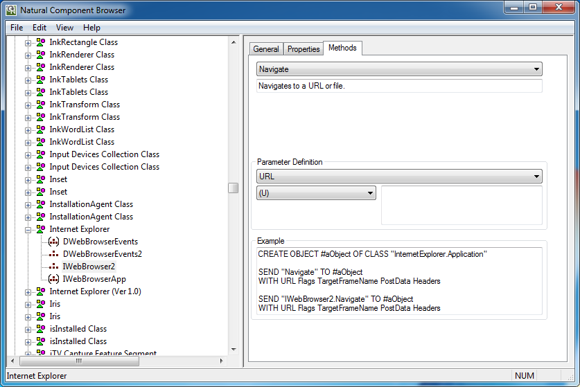
The Component Browser can be used to view ActiveX components which are available for developing NaturalX applications. It presents the information in a way that is especially useful to Natural application developers.
The Component Browser comprises the following features:
Available ActiveX components and their dispatch and dual interfaces are listed.
Data types are mapped to Natural data formats.
The external components' help files are directly accessible.
Natural programming examples are automatically generated.
Many programming errors can be prevented.
The Component Browser uses a split window. The left pane contains a tree view that represents the available external components, and the right pane contains the data view that provides information on a selected node item.
The Component Browser documentation describes the elements of the Component Browser window:
At startup the Component Browser's tree view consists of four nodes that group the available external components:
All ActiveX Components
This group lists ActiveX controls and Automation Objects.
ActiveX Controls
This group lists only the ActiveX controls.
Automation Objects
This group lists the Automation Objects.
Interfaces
This group lists all dual and dispatch interfaces that can be addressed in a Natural application. In this context, their relation to an ActiveX component is not taken into account.
In general, a node in the tree view represents either an ActiveX component or an interface. It provides textual information on the node and has a specific icon assigned that represents additional information.
The following table lists all available nodes with their icons and gives a short description:
| Type | Icon | Description |
|---|---|---|
| Group |
|
Group node. |
| ActiveX component | 
|
ActiveX component. |
| Interface | 
|
Interface of the current ActiveX component. |
| Default interface | 
|
Default interface of the current ActiveX component. |
By default, the ActiveX component nodes are inserted in alphabetical order of their external names. Interface nodes are always inserted in alphabetical order.
 To sort ActiveX component nodes according to their ProgID
From the View menu, choose Show by ProgID.
The data view uses a property sheet to display the specific information for a selected node. This sheet consists of four tabbed pages:
General
Components and interface specific information such as name, globally unique identifier (GUID) and help file name. It is always the active page if a new node is selected.
Properties
Specific information on the properties offered by an interface. These are, for example, the property's name and type.
Events
Specific information on a component's event interface. These are, for example, the event's name and parameters.
Methods
Specific information on the methods and complex properties (that is, properties with parameters) offered by an interface. Displayed are, for example, the method's name, return type and parameters.
These pages are discussed in more detail in the context of interaction between tree and data view.
The contents of the data view depend on the node selected in the tree view.
If any of the group nodes All ActiveX Components, ActiveX Controls, Automation Objects or Interfaces is selected, the data view remains empty.
This section describes the tabbed pages that may be displayed in the data view.
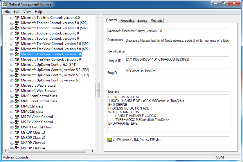
If a component node is selected, all four tabbed pages are available. The page General provides the following information:
| Name | Component name |
|---|---|
| Description | Short textual description. |
| Unique ID | GUID. |
| ProgID | ProgID. |
| Example | Example Natural source code. See also Application Development Support. |
| Help | Help file name. This file can be opened by choosing
 |
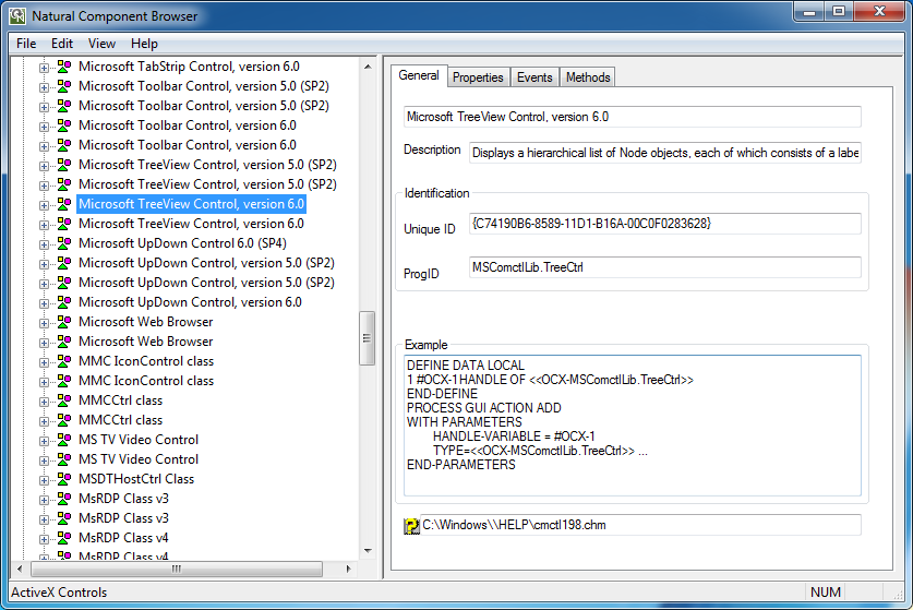
If a component is selected and the page Properties, Events or Methods is activated, the information displayed on this page refers to the default interface.
If an interface node is selected, the number of available tabbed pages depends on the type of the interface.
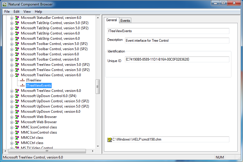
If an interface is browsed in the context of a component and if it is an event interface, then only the pages General and Events are set.
Otherwise, the pages General, Properties and Methods are set.
Each page is described in the following section.
The page General provides the following information:
| Name | Interface name |
|---|---|
| Description | Short textual description. |
| Unique ID | GUID. |
| Help | Help file name. This file can be opened by choosing
|
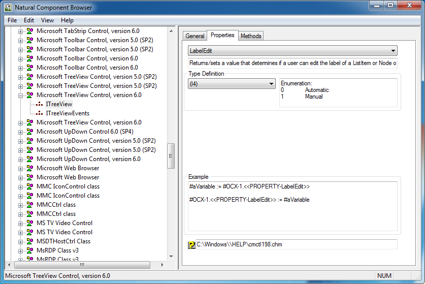
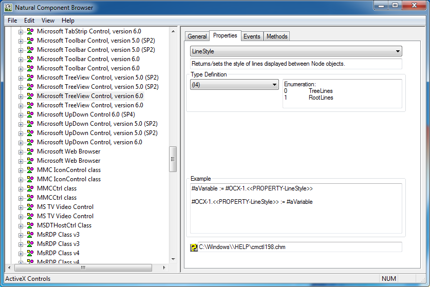
The page Properties provides the list of properties that belong to the selected interface. For a specific property, the following information is displayed:
| Description | Short textual description for the selected property. |
| Type Definition | List of valid Natural data formats for the property's type. Additional type info on the selected Natural data format, e.g. valid values for enumeration types. |
| Example | Example Natural source code. See also Application Development Support. |
| Help | Help file name. This file can be opened by choosing
|
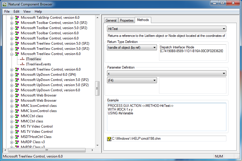
The page Methods provides the list of methods that belong to the selected interface. This list includes properties with parameters. For a specific method or complex property, the following information is displayed:
| Description | Short textual description for the selected method. |
| Return Type Definition |
List of valid Natural data formats for the method's type.
|
| Parameter Definition |
List of parameters that are required by the method. |
| Example | Example Natural source code. See also Application Development Support. |
| Help | Help file name. This file can be opened by choosing
|
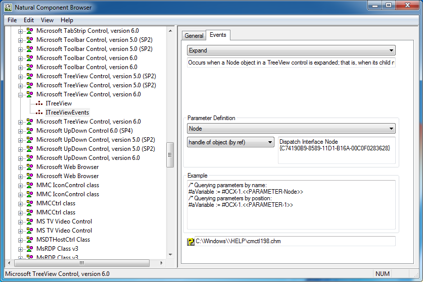
The page Events provides the list of events that belong to the selected event interface. For a specific event, the following information is displayed:
| Description | Short textual description for the selected event. |
| Parameter Definition |
List of parameters that are required by the event. List of valid data Natural data formats for each parameter together with additional info on the call mode (by ref). Additional type info on selected Natural data format, e.g. Name and GUID of the interface if a handle of object corresponds to a dispatch interface. This interface can then be found in group Interfaces. |
| Example | Example Natural source code. See also Application Development Support. |
| Help | Help file name. This file can be opened by choosing
|
The following menus are available in the Component Browser window:
| Menu | Item | Description |
|---|---|---|
| File | EXIT | Leaves the Component Browser. |
| Edit | Copy |
This item is enabled if the data view has the focus. |
| Copy CLSID to Clipboard |
This item is enabled if either the tree view or the data view
has the focus. |
|
| Copy ProgID to Clipboard |
This item is enabled if either the tree view or the data view
has the focus. |
|
| Find Unique ID |
This item is enabled if the tree view has the focus. |
|
| View | Show by ProgID |
This item is enabled if the tree view has the focus. |
| Show Current Version |
This item is enabled if the tree view has the focus. |
|
| Status Bar | Shows or hides the status bar. | |
| Refresh |
This item is enabled if the tree view has the focus. |
|
| Help | About Component Browser |
This item is enabled if either the tree view or the data view
has the focus. |
The Example boxes in the pages of the data view provide detailed examples of Natural source code. These examples show how to use a selected object in a Natural application. Which statements are generated depends on the object's type.
The example source code or just parts of it can be selected, copied to the clipboard and used directly in an application. Only variable names might have to be adapted to meet the application's requirements.
 To copy frequently used identifiers to the clipboard
From the Edit menu, choose Copy CLSID to Clipboard.
Or:
From the Edit menu, choose Copy ProgID
to Clipboard.
This section covers the following topics:
For ActiveX controls, the appropriate PROCESS
GUI statement is generated that shows how to use these components
in Natural applications.
This section describes example source code shown on the pages provided for items contained in the ActiveX Controls node.
The example on the page General shows how an
object of this type is instantiated. Here #OCX-1 denotes a
variable that can be adapted to the current application.
The example on the page Properties shows how to
assign a property to a variable and how to assign a variable to a property.
Here #OCX-1 is the defined object handle and
#aVariable refers to an application-specific variable. Both names
can be adapted if required.
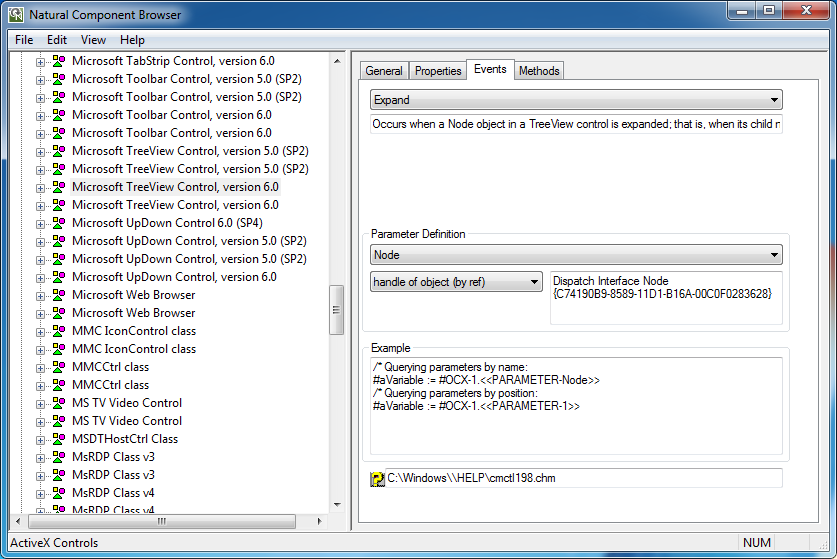
The example on the page Events shows how to query
event parameters by name or by position. Here #OCX-1 is the
defined object handle and #aVariable refers to an
application-specific variable. Both names can be adapted if required.
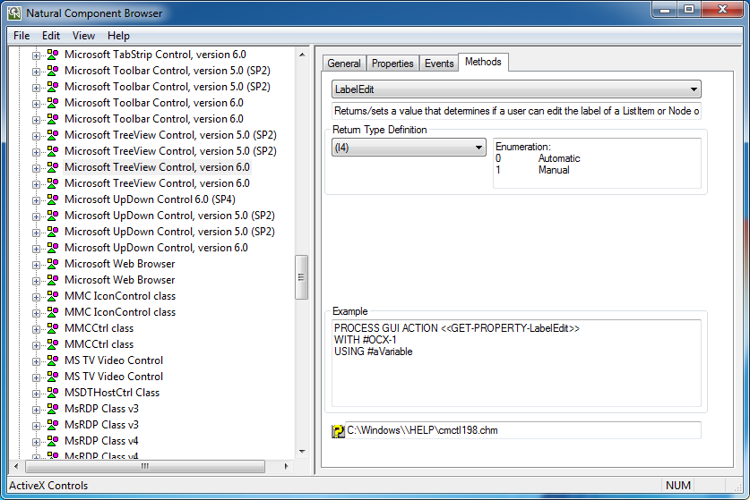
The example on the page Methods shows how to use
methods and properties with parameters. Here #OCX-1 is the defined
object handle and #aVariable refers to an application-specific
variable. Both names can be adapted if required. The actual parameter names are
already inserted into the statement if they are available. Otherwise, default
parameter names such as P0 and P1 are used as
placeholders. These names can be replaced by application-specific
variables.
This section describes example source code shown on the pages provided for items contained in the Automation Objects node.
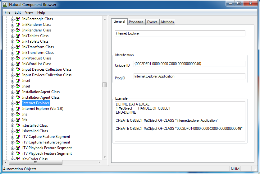
The example on the page General shows how an
object of this type is instantiated. Here #aObject denotes a
variable that can be adapted to the current application.
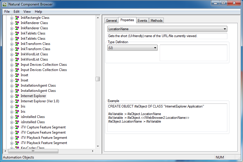
The example on the page Properties shows how to
assign a property to a variable and how to assign a variable to a property.
Here #aObject is the defined object handle and
#aVariable refers to an application-specific variable. Both names can be
adapted if required.
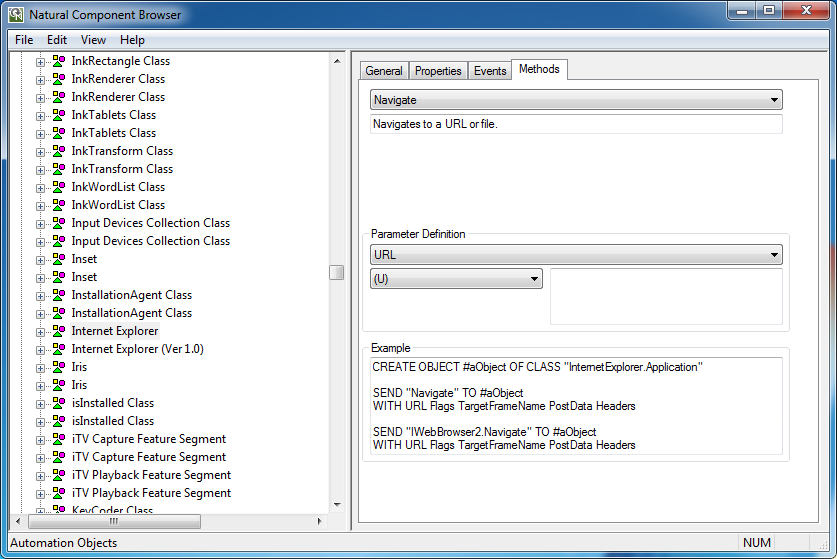
The example on the page Methods shows how to use
methods. Here #aObject is the defined object handle and
#aVariable refers to an application-specific variable. Both names
can be adapted if required.
The actual parameter names are already inserted into the statement if
they are available. Otherwise, default parameter names such as P0
and P1 are used as placeholders. These names can be replaced by
application-specific variables.
For interfaces that belong to group Interfaces and
that are not considered in the context of a class, the examples are generated
as for Automation Objects. Only the CREATE OBJECT
statement is left aside.
This section describes example source code shown on the pages provided for items contained in the Interfaces node.
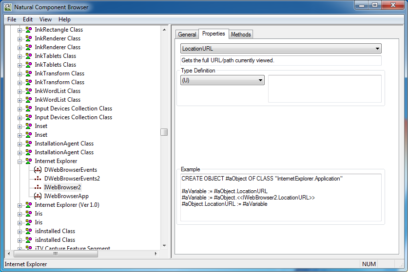
The example on the page Properties shows how to
assign a property to a variable and how to assign a variable to a property.
Here #aObject is the defined object handle and
#aVariable refers to an application-specific variable. Both names
can be adapted if required.
The example on the page Methods shows how to use
methods. Here #aObject is the defined object handle and
#aVariable refers to an application-specific variable. Both names
can be adapted if required.
The actual parameter names are already inserted into the statement if
they are available. Otherwise, default parameter names such as P0
and P1 are used as placeholders. These names can be replaced by
application-specific variables.
