Event Modeler layout
To begin learning how to use Event Modeler, it is helpful to examine a sample scenario in Event Modeler. To do this:
1. Select Start > Programs > Software AG > Apama 5.3 > Apama Studio.
2. On the Apama Studio Welcome page, click Samples, then click Apama Samples.
3. In the list of demos that appears, click Statistical Arbitrage and click Open to open the demo application’s project in Apama Studio.
4. In the Apama Studio Workbench Project View, expand Scenarios and double-click StatisticalArbitrage.sdf. This is the scenario definition file. When you double-click it, it opens in Apama Studio’s Event Modeler editor.
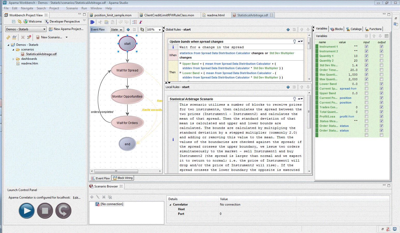
The Event Modeler editor is divided into a number of areas. In the panel on the left (the Event Flow tab) click on the double-bordered oval shape marked start. Your display will now look as follows: xxx
Event Modeler editor layout
This is the default view. Event Modeler displays the following primary areas:
 Event Flow
 Global Rules
 and
Local Rules
Tabs for
Variables,
Blocks,
Catalogs, and
Functions.
At the bottom of Event Modeler, there are tabs for Event Flow and Block Wiring. When you click the Block Wiring tab, the Event Flow and Rules panels diappear and the Block Wiring tab appears.
During its lifetime, a scenario instance transits through a number of execution states, starting from the
start state, and eventually ending at the
end state (shown in the
Event Flow tab). Event flows are described in
About event flow states.
Each state consists of a list of rules that are executed in a particular sequence. Each has a condition that needs to be met for its embedded actions to be executed, and once those actions are complete, it can specify whether the following rules are to be processed next or the scenario should transit directly to another state. These rules appear in the
Global Rules and
Local Rules panels. Rules are examined in
How rules define scenario behaviorThe
Variables tab lists any variables defined in the scenario. Scenario variables are placeholders for important information that needs to be referred to and modified during the scenario’s execution. They also reflect what data can be collected from the user or sent back to be displayed to the user as results or progress updates. Variables will be described in
About scenario variables.
The
Blocks tab lists any blocks that are being used by this scenario. Blocks are pre-packaged modules that can be imported and used within scenarios. They can accept inputs, execute some logic of their own, and generate output. Like a scenario, blocks can themselves have configuration parameters as well as input and output feeds. Blocks can also carry out specialized operations. See
About blocks for details.
The
Catalogs tab lists the reusable, ready packaged blocks that are available for use in this scenario. Event Modeler comes with a selection of standard blocks, and these are documented in
Using Standard Blocks.
Using the Catalogs tab describes usage of the
Catalogs tab.
The
Functions tab lists the functions that are available for use in this scenario. Event Modeler comes with a selection of standard functions, and these are documented in
Using the Functions tab.
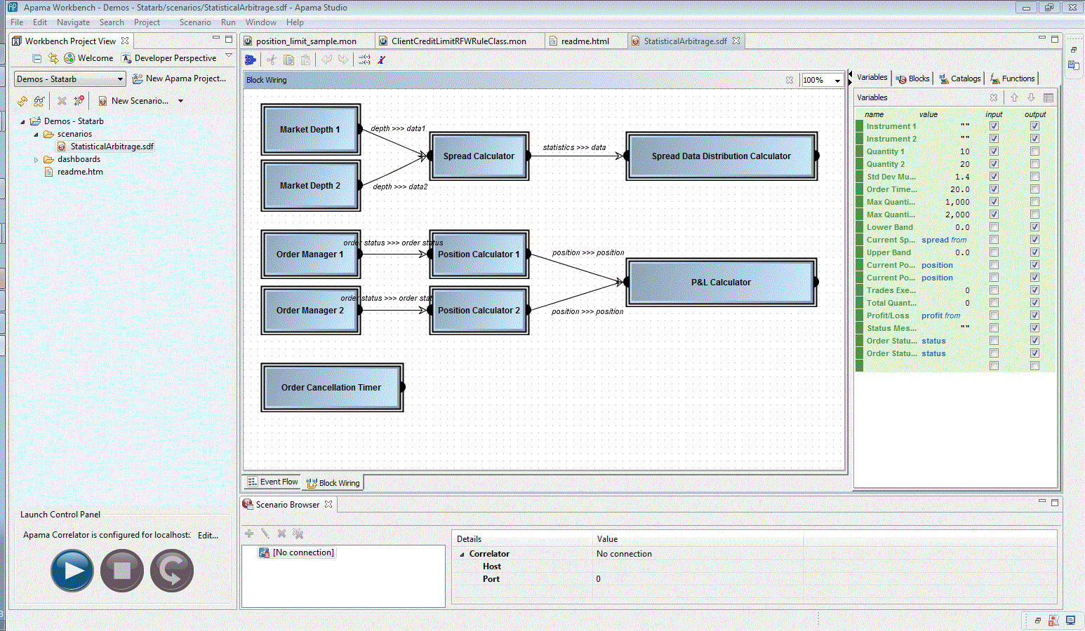
Minimize the panels that are not part of Event Modeler and then click the Block Wiring tab that appears below the Event Flow tab. The main view changes to show the Block Wiring tab. The Event Modeler display now looks like this:
Block Wiring tab
This tab shows the blocks that are being used within this scenario, and whether those blocks are wired together; that is, whether the outputs of one block are acting as the inputs of another. This functionality will be described in
Switching blocks. The specific functionality of all the tabs will be covered in depth in
Using Event Modeler.


