Creating row-leaf format control trees
In the row-leaf table format, there is one row in the table for each leaf node in the tree. A leaf node is added to the tree for each row in the table attached to the valueTable property. The path to a leaf node (that is, the ancestor nodes of the leaf) is determined by the values in each of the table columns specified by the nodeIndexColumnNames property. When the valueTable property is attached to the scenario instance table, the tree's nodeIndexColumnNames property is typically set to the same columns that are specified in the Display variables field of the Attach to Apama dialog.
To illustrate how to create a tree using the row-leaf format, consider a table that has two columns, App Name and PID, and the following rows:
App Name | PID |
app0 | 1000 |
app0 | 1004 |
app0 | 1008 |
app1 | 1001 |
app1 | 1005 |
Set tree control properties as follows:

Attach the tree control object's
valueTable property to Apama as you would attach any table object. In the
Attach to Apama dialog, in the
DisplayVariables field, select the variables
App Name and
PID.
Set the
valueTableFormat property to the
Row-Leaf format.
Set the
nodeIndexColumnNames property to
App Name;PID.
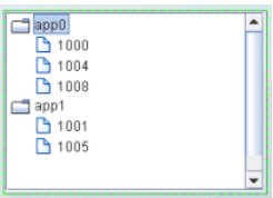
The following image illustrates the structure of the tree. There are two nodes labeled app0 and app1. Node app0 has three child nodes labeled 1000, 1004, 1008. Node app1 has two child nodes, labeled 1001 and 1005.
Suppose we add another column, AgentName, by selecting that variable from the Display Variables field of the Attach to Apama dialog. The table has the following rows:
AgentName | App Name | PID |
Agent1 | App0 | 1000 |
Agent1 | App0 | 1004 |
Agent1 | App0 | 1008 |
Agent1 | App1 | 1001 |
Agent1 | App1 | 1005 |
Agent2 | App0 | 1000 |
Agent2 | App0 | 1004 |
Agent2 | App1 | 1001 |
We also update the tree control nodeIndexColumnNames property to AgentName;App Name;PID.
The following figure illustrates the new structure of the tree. The tree now has two top-level nodes labeled Agent1 and Agent2, each with two child nodes, app0 and app1.
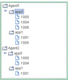
As illustrated above, the label string for a node at depth N is taken from the Nth column in the nodeIndexColumnNames property. Therefore, the labels for the top-level nodes come from the first column in the nodeIndexColumnNames property (AgentName), the labels for the second-level nodes come from the second column in nodeIndexColumnNames property (App Name), and so forth.
To specify node labels from a different set of valueTable columns, use the nodeLabelColumnNames property. Enter a semicolon-separated list of column names in the nodeLabelColumnNames property, one for each level in the tree, where the Nth column name in the list contains the labels for tree nodes at depth N.
To modify tree control icons or configure tree control icon behavior, see
Configuring tree control icons.
Copyright © 2013
Software AG, Darmstadt, Germany and/or Software AG USA Inc., Reston, VA, USA, and/or Terracotta Inc., San Francisco, CA, USA, and/or Software AG (Canada) Inc., Cambridge, Ontario, Canada, and/or, Software AG (UK) Ltd., Derby, United Kingdom, and/or Software A.G. (Israel) Ltd., Or-Yehuda, Israel and/or their licensors.