This document covers the following topics:
There are two ways in which the data stored in a DL/I database can be
converted to Adabas file(s): an automated procedure and a manual one. Both
procedures create a sequential file (the unloaded database), which is input to
the standard Adabas Compression utility, ADACMP. After the data
compression by ADACMP, the Adabas utility ADALOD
(Initial File Loading and Mass Update Utility) will populate the Adabas file(s)
using the functions "LOAD" and "UPDATE".
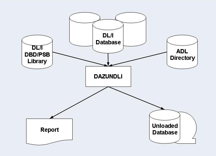
The difference between the two procedures lies in the fact that the
automated procedure uses a standardized Unload utility, DAZUNDLI.
This utility unloads the original DL/I database in one step. In contrast, the
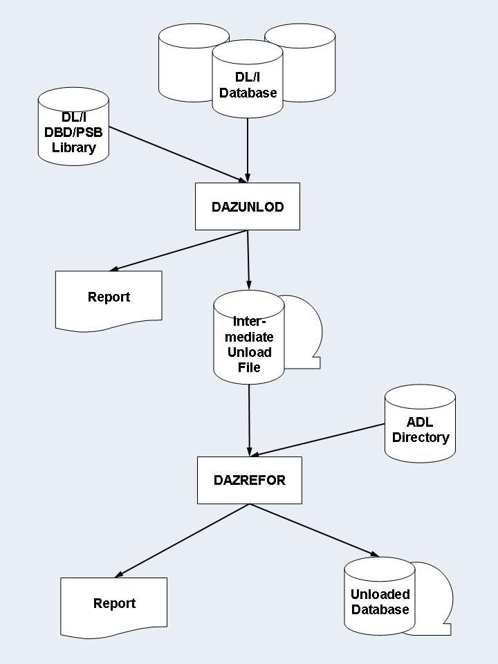
manual procedure creates the unloaded database in two steps, using a customized
Unload utility, DAZUNLOD, in the first step, and a standardized
Reformat utility, DAZREFOR, in the second.
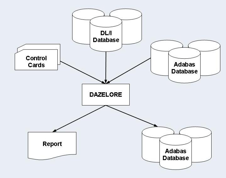
In the automated procedure, the Unload utility DAZUNDLI
accesses DL/I to read the segments in the database, while at the same time
using the ADL to create the unloaded database. The utility thus runs in mixed
mode, and the PSB and DBD used need to be generated according to mixed mode
conventions (i.e. as both DL/I and ADL PSBs and DBDs). Limited data editing is
possible during unloading of the DL/I database: all or specific numeric fields
may be checked for valid numeric contents. You can limit the amount of unloaded
data by specifying various parameters.
The manual procedure uses a customized Unload utility,
DAZUNDLI, to unload the original DL/I database, and a standardized
Reformat utility, DAZREFOR, to create the unloaded database.
DAZUNLOD is a normal DL/I application program which reads the DL/I
database from the beginning to the end and creates an intermediate unload file.
DAZREFOR is a normal mode ADL application program which reads the
intermediate unload file and creates the input file for ADACMP.
The PSB and DBD used for both DAZUNLOD and DAZREFOR
may be the same.
As you have to customize DAZUNLOD in order to unload a DL/I
database, you are also able to edit the data read before you create the
intermediate unload file. You may, for example, want to do this in situations
where numeric data has not been stored in numeric fields.
The differences between the automated and the manual procedure are summarized on the following pages.
All PSBs created for the ADL utilities mentioned in this section (for
example, the unload and connection PSBs) must be installed with the option
LANG=ASSEM or LANG=COBOL in the PSBGEN
statement.
| Automated Procedure | Manual Procedure |
|---|---|
| The ADACMP input file is created in one step. | The ADACMP input file is created in two steps. |
| The Unload utility runs in mixed mode | The Unload utility runs as a normal DL/I application. The Reformat utility runs as a normal ADL application |
| Limited data editing possible during the unload procedure. | The Unload utility has to be customized. Data editing is therefore possible. |
This section describes how to unload all the data of a database. Refer to the next section for details on how to unload data selectively.
To use the automated method of conversion to unload the data stored in a DL/I database, perform the following steps:
Run the original DL/I DBD through the CBC utility (see the section ADL Conversion Utility for DBDs and PSBs in this documentation).
The PSB created must contain two PCBs, both of which must be based on the original DBD and must reference all of its segments. The first PCB is used to unload the data, while with the help of the second, the data is prepared for the reloading. Run this PSB through the CBC utility. Note that if the DBD is involved in logical relationships and contains logical child segments, these must also be referenced by the PCBs (this also applies to virtual logical child segments).
Run the PSB through the DL/I PSBGEN. The PSB created in
the previous step can be used as the DL/I unload PSB. Note that, in contrast to
the previous step, it is not absolutely necessary for this PSB to contain two
identical PCBs, as one suffices.
Unload the data from the DL/I database by running the ADL Unload
utility, DAZUNDLI. DAZUNDLI is executed as a mixed
mode program (see the section
Batch
Installation and Operation in the ADL
Interfaces documentation ). The mixed mode control statement must
have the following layout:
UNL,DAZUNDLI,psbname
where psbname is the name of the unload PSB.
The unloaded data is subsequently stored in a sequential file. You can
use the sample JCL in the source library member ADLDBC4 (z/OS) or
ADLDBC4.J (z/VSE) as an example. The JCL/JCS requirements for
DAZUNDLI are given at the end of this section.
During unloading of the DL/I database contents, it is possible to let
ADL automatically correct either all numeric fields or specific numeric fields.
Packed (TYPE=P) and zoned decimal (TYPE=Z) fields are
checked by ADL for valid packed or zoned decimal value contents. If they do not
contain a valid packed or zoned decimal value, a null value (i.e. a packed zero
for packed fields and a zoned decimal zero for zoned decimal fields) is
substituted. This procedure can be activated for all numeric fields within a
DBD or for specific ones only, using extra control cards for
DAZUNDLI. The syntax of these control cards is as follows:
MODE=CHECKNUM
SEGM=segname,FIELD=fldname
SEGM=
where segname is the name of segment within the unloaded DBD, and fldname is the name of a numeric field within this segment.
Specifying only the control card MODE=CHECKNUM activates
checking of all numeric fields within the DBD. Specifying one or more
SEGM/FIELD control cards limits the checking to only those fields
specified. Omitting the control cards altogether, or specifying
MODE=STANDARD, deactivates checking of any numeric fields.
The automated procedure described in the previous section may also be
used to unload only a part of the database. This can be achieved by modifying
the unload PSB or by specifying additional control statements for the
DAZUNDLI utility. Note that if a logical child segment occurrence
is unloaded, the corresponding logical parent segment occurrences have to be
unloaded as well.
This section covers the following topics:
If the first PCB in the unload PSB does not contain all of the segments of the original DBD, only the referenced ones will be unloaded. The second PCB has to reference at least the segments of the first PCB. Note that a logical relationship between two DBDs requires a specification of the logical child segment either on both sides or on none.
In order to unload the database in an alternate sequence, the first PCB
in the unload PSB may refer to a secondary index as the processing sequence. In
this case the "START" and "END"
parameters of DAZUNDLI correspond to the values of the secondary
index source fields.
The secondary index must have the root segment as target. It is recommended to use only those secondary indices which have a one-to-one relation to the root segment, otherwise the repetition of the data will lead to problems during the reload.
The number of unloaded records may be limited by specifying the
"NUMREC" parameter for DAZUNDLI. The syntax
of this control card is as follows:
NUMREC=number_of_records
where number_of_records is the maximum number of unloaded records. This number can be up to 8 digits long.
Every occurrence of every segment counts as one record. Thus if the "number_of_records" is reached, it may be that not all dependent segments of the last unloaded root segment have been unloaded.
Unload at most 1000 records from the database:
NUMREC=1000
The number of unloaded root segment occurrences may be limited by
specifying the "NUMROOT" parameter for
DAZUNDLI. The syntax of this control card is as follows:
NUMROOT=number_of_roots
where number_of_roots is the maximum number of unloaded root segment occurrences. This number can be up to 8 digits long.
If the NUMREC parameter is not specified, the
root segments will be unloaded together with all their dependent segments.
Unload at most 50 root segment occurrences together with their dependents:
NUMROOT=50
The range of unloaded root segment occurrences may be limited to
specific values by defining the "START" or
"END" parameter for DAZUNDLI. The syntax of
these control cards is as follows:
START=string
END=string
where string is either the start or end value and must be of the following format:
'char_string'
X'hex_string'
where
| char_string | may contain any character |
| hex_string | must consist of pairs of the characters 0-9, A-F, where each pair will be interpreted as a hexadecimal character. |
A string may be continued by ending the current line with a comma (","). The following line must contain only a string without any keyword being specified. This continued string may start in any column, may itself be continued and may have either format. Thus, it is possible to build up a start and end value from both character and hexadecimal strings.
The database will be unloaded from the start to the end value,
inclusively. The end value might not be reached if the
NUMREC or NUMROOT parameter is
specified.
The values refer to the root sequence field or, if an alternate
sequence is chosen, to the secondary index field. If the string is longer than
the referenced field, it is truncated at the right. If it is shorter, it is
padded at the right with low values (hexadecimal X'00') or high
values (X'FF') for the start or end value respectively.
Packed values may be specified in hexadecimal format. It is recommended to use the correct field length, as this avoids an undesired truncation or padding of the packed values.
The following example shows how to unload data for the root sequence
field range from "EDV" to "MATH" inclusively:
START='EDV'
END='MATH'
The following example shows how to unload all data with a root sequence
field value of "XYZ" followed by a hexadecimal
"01":
START='XYZ',
  X'01'
END='XYZ',
  X'01'
Specific root segment occurrences may be unloaded by specifying the
ROOTKEYS parameter. The syntax of this control card is
as follows:
ROOTKEYS
key values
or
ROOTKEYS=SEQ
In the first case, the ROOTKEYS must be the last
parameter for DAZUNDLI. It is followed by one or more root
sequence field values. If ROOTKEYS=SEQ is specified, the
root sequence field values are read in from DAZIN3. In this case,
it is not required that the ROOTKEYS parameter is the
last parameter. The corresponding root occurrences are unloaded together with
all dependents. When the ROOTKEYS parameter is
specified, the START and END
parameter must not be used.
The following example shows how to unload the data for the root
sequence fields with the values 'EDV' and
'GERMAN'.
ROOTKEYS
EDV
GERMAN
In a HDAM database, the sequence of the root occurrences is
defined by the randomizing module. This mostly does not correspond to the root
key sequence. When such a database is unloaded (without additional parameters),
the reloaded Adabas data is randomly distributed over the data blocks. This
results in a poor performance for sequential reads, since for each new accessed
root segment occurrence, a physical I/O is required.
Thus it is recommended to unload the data in root key sequence. To do
this, use any application which writes all the root sequence field values (and
only these) to a sequential file. Sort these values by using any sort utility.
These sorted values can now be used as key values for the
ROOTKEYS parameter of the DAZUNDLI utility
as described above. This forces DL/I to unload the database in the given
sequence and the loaded Adabas data is no longer randomly distributed over the
data blocks.
If the data has been initially loaded in the randomized sequence, i.e.,
without the ROOTKEYS parameter, it can be sequenced by
unloading and reloading it from the ADL files. This time the
ROOTKEYS parameter is not required, because ADL uses the
root sequence field always as sort key.
The following keywords are available for DAZUNDLI. For a
detailed description refer the previous sections. The keywords are read from
the control input for DAZUNDLI (see the sections z/OS JCL
Requirementsor z/VSE JCS Requirements later in
this documentation).
| Keyword | Explanation | Possible values | Default |
|---|---|---|---|
| END | Indicates the end value of the unload. The value refers to the root sequence field, or if an alternate processing sequence is specified, the corresponding secondary index field. The value may be continued by putting a comma after it. | Any character string or an "X" followed by pairs of the characters 0-9, A-F, which will be interpreted as hexadecimal characters. Both types of string have to be enclosed by quotation marks. | None. If no other condition is met, the database is unloaded until the end of the database is reached. |
| FIELD | The name of a numeric field to be checked for valid values. This keyword must be preceded by the SEGM keyword. | Any numeric field name. | None. |
| MODE | Indicates, whether numeric fields are to be checked for valid values. The MODE keyword can be overridden by the SEGM keyword. | STANDARD - do not check numeric
fields. CHECKNUM - check all numeric fields. |
|
| NUMREC | The maximal number of unloaded records. | 1 - 99999999 | No limit. |
| NUMROOT | The maximal number of unloaded root segment occurrences. | 1 - 99999999 | No limit. |
| ROOTKEYS | Unload specific root key values together with their dependents. | None - the key values are supplied after the
ROOTKEYS parameter. SEQ - the key values are in DAZIN3. |
If ROOTKEYS is not specified at all, all root key values are unloaded. |
| SEGM | The name of a segment with a numeric field to be checked for valid values. This keyword must be followed by the FIELD keyword. Once the SEGM keyword is specified, only the corresponding fields will be checked, regardless of the MODE keyword. | Any segment name. | None. |
| START | Indicates the start value of the unload. The value refers to the root sequence field, or if an alternate processing sequence is specified, the corresponding secondary index field. The value may be continued by putting a comma after it. | Any character string or an "X" followed by pairs of the characters 0-9, A-F, which will be interpreted as hexadecimal characters. Both types of string have to be enclosed by quotation marks. | None. |
To use the manual conversion method to unload the data stored in a DL/I database, perform the following steps:
Run the original DL/I DBD through the CBC utility (see the topic ADL Conversion Utilities for DBDs and PSBs in this section).
The PSB created must contain one PCB: this must be based on the
original DL/I DBD and must reference all segments of the DBD. Run the PSB
through the DL/I PSBGEN. Note that if the DBD is involved in
logical relationships and contains logical child segments, these must also be
referenced by the PCB (this also applies to virtual logical child
segments).
Run the PSB created in Step 2 through the CBC utility (see the topic ADL Conversion Utilities for DBDs and PSBs in this section).
Write, assemble and link edit an unload program to unload the data from
the DL/I database. An example of an unload program is provided as the source
member DAZUNLOD (z/OS) or DAZUNLOD.A (z/VSE) in the
Source Library on the installation tape.
Write the unload program in Assembler using the standard programming conventions for this language.
The unload program reads the DL/I database by issuing unqualified
GN calls until it reaches the end. If the standardized reformat
program DAZREFOR is to be used in Step 5 (below) to create the
input file for ADACMP, the segment occurrences read have to be
written out to the intermediate unload file as variable length records with the
following record layout:
| Bytes | Explanation |
|---|---|
| 1-4 | Length of the record, including this field (standard convention for variable length record). (4 bytes) |
| 5-12 | The DL/I segment name taken from the SENSEG feedback area in the user PCB. (8 bytes) |
| 13- | The DL/I segment data taken from the I/O area. Note that if the segment is of variable length, the length bytes are part of the segment data and must be included as the first two bytes in the segment I/O area. |
The unload program is executed as a normal DL/I application program using the DL/I unload PSB.
When using the sample program on the installation tape, you should bear
in mind that it uses the ADL internal request handler, DAZBRQH. It
is therefore independent of the operating system used.
When DAZBRQH is being used, certain conventions need to be
followed. These are described in detail in the example program itself, but are
summarized briefly below.
Save and work areas for the request handler must be provided by the
caller. The first fullword of this area must contain the start address of the
area itself, i.e. it must be pointing to itself. In the sample program, this is
achieved by using the macro SAVEAREA. For z/VSE users, this macro
may also be used to change the block size of the intermediate unload file
dynamically.
Requests are issued by calling the request handler as a subroutine,
with the registers R0 and R1 being used to pass the
necessary parameters. In the sample program, this is achieved by using the
REQUEST macro.
All files are opened by the request handler dynamically, but have to be closed by the caller.
DAZBRQH
Because the sample program uses the internal request handler, it must
be linked with DAZBRQH.
The intermediate unload file created in Step 4 is read and each
unloaded segment is put through ADL. The input file for ADACMP is
created. The standardized reformat program in the Load Library,
DAZREFOR may be used if the intermediate unload file has been
created according to the layout conventions in Step 4.
If the standardized reformat program does not meets your requirements,
you can write your reformat program. An example of a reformat program is
provided as the source member DAZREFOR (z/OS) or
DAZREFOR.A (z/VSE) in the Source Library.
The reformat program reads the intermediate unload file and issues a
load call against ADL for each unloaded segment occurrence. A load call has the
same syntax as a normal DL/I insert call, but LOAD is specified as
the function instead of ISRT.
The parameters for the LOAD call are as follows:
| Parameter | Explanation |
|---|---|
| Parameter 1 | (optional) The number of parameters (4) that follow. |
| Parameter 2 | The function is LOAD. |
| Parameter 3 | The PCB address for the first and only PCB in the reformat PSB. |
| Parameter 4 | The I/O area as read from the intermediate unload file. |
| Parameter 5 | An unqualified SSA specifying the name of the segment as read from the intermediate unload file. |
The standardized reformat program DAZREFOR is executed as
a normal mode ADL program (see the section
Batch Installation and
Operation in the ADL Interfaces documentation).
The execution parameters must have the following layout:
REF,DAZREFOR,psbname
where psbname is the name of the ADL reformat PSB.
Like DAZUNLOD, DAZREFOR uses the ADL internal
request handler, DAZBRQH. The same conventions apply.
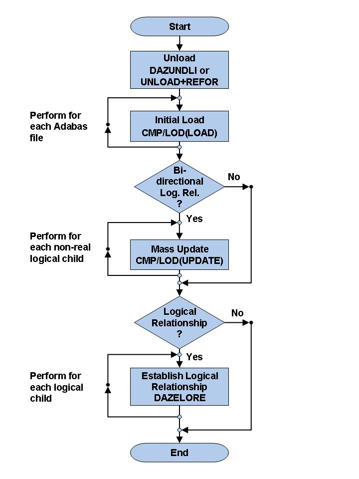
The manual and the automated procedures use the same methods of loading Adabas files. You must perform the following steps:
* Only for databases related via a bidirectional logical
relationship and if the standard or simplified procedure of
DAZELORE is used to establish logical relationships.
This section covers the following topics:
Each Adabas file used to store the converted data is loaded
individually using the standard Adabas utilities (ADACMP,
ADALOD).
The sequential file produced in the previous steps is taken as input
for the ADACMP step, as are the ADACMP statements
generated by the CBC utility in Step 1.
Each Adabas file used must be loaded with the option
USERISN. This applies to both the ADACMP and the
ADALOD steps (for ADACMP it is already generated by
the CBC utility), as the ISNs are automatically generated by the ADL.
Step 6 needs to be run once for each of the Adabas files used to store the DL/I database.
Note that the initial load does not load the data of a paired logical child segment of a bidirectional logical relationship. This is performed by the next step, if required at all.
You may use the sample JCL (JCS) in the member ADLDBC6
(ADLDBC6.J) as an example of an initial load job under z/OS
(z/VSE).
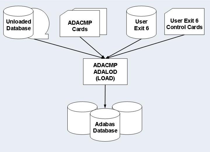
The ADACMP step uses Adabas User Exit 6. This exit consists of two parts which were linked together during the DBD conversion procedure (see the section ADL Conversion Utilities for DBDs and PSBs in this documentation):
Fixed Part
The fixed part consists of the DAZUEX06 module, which expands each input record on the unload file to its full decompressed size before passing it on to ADACMP.
User Exit 6 Extension
The User Exit 6 extension is generated by the CBC utility and contains information on the structure of the DBD being converted, and the default record layouts of the Adabas file(s) used to store the converted data.
Adabas User Exit 6 needs a control statement to indicate which Adabas file should be loaded. The syntax of this control statement is as follows:
FNR=nnnnn,MODE=LOAD
where nnnnn is the file number of the Adabas file to be loaded.
Information on how to load the file is provided at the end of this section.
You only need to perform this step if the database being converted is involved in bidirectional logical relationships. In this case, the data originating from a bidirectional logical segment is stored only once, in an Adabas file. The way in which the data was stored under DL/I (virtual or physical pairing) has no effect on this.
You must not perform this step when the Special or Turbo procedure is used to establish logical relationships (see the following section: Establishing Logical Relationships).
Within a bidirectional logical relationship, the real logical child
segment can be defined as the logical child segment for which an Adabas file
number and Adabas fields are generated. The paired logical child segment can be
defined as the logical child segment with which the real logical child segment
is paired. The reports produced by the CBC utility during conversion of the
physical DBDs show which Adabas file contains the logical child segment data,
and therefore which of the two logical child segments is the real logical child
segment. Once all Adabas files storing data originally contained in DL/I
databases related via a bidirectional logical relationship have been loaded,
the Adabas Mass Update utility ADALOD with the UPDATE
function must be run for all Adabas files which contain data originating from a
bidirectional logical child segment.
The real logical child segment occurrences are unloaded during the
unload of the DL/I database in which they were stored. They are subsequently
loaded with an initial load using the Adabas utilities ADACMP and
ADALOD. The paired logical child segment occurrences are unloaded
separately during the unload of the DL/I database in which they were stored and
must be added separately to the Adabas file in which the real logical child
segment occurrences have been loaded. This is done using ADALOD
(UPDATE). To produce the input for ADALOD
(UPDATE), run the Adabas Compression utility ADACMP
with the following input:
The ADACMP statements for the Adabas file used to store
the bidirectional logical child segment data, i.e. the Adabas file for the
real logical child segment. Note that because the output produced by
the ADACMP utility is input to the ADALOD
(UPDATE) utility, the USERISN option must not be
specified and has to be removed from the ADACMP statements before
you run the ADACMP step.
The Adabas User Exit 6 for the Adabas file used to store the bidirectional logical child segment data, i.e. the Adabas file for the real logical child segment.
The unloaded DL/I database containing the paired logical child segment data.
A User Exit 6 control statement specifying a mass update run with the format:
FNR=nnnnn,MODE=MASS,LC=name
where
| nnnnn | is the file number of the Adabas file containing the bidirectional logical child segment data, i.e. the Adabas file for the real logical child segment, and |
| name | is the name of the paired logical child segment. |
You may use the sample JCL (JCS) in the member ADLDBC7
(ADLDBC7.J) as an example of a mass update under z/OS (z/VSE).
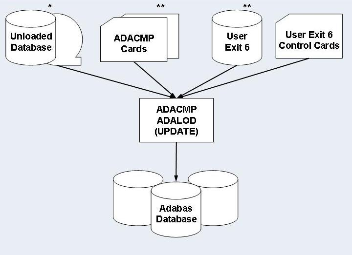
* Unloaded Database containing the paired logical child segment data.
** ADACMP Cards and User Exit 6 generated for the real logical child segment.
When the first seven unload/load steps have been successfully completed,
the data stored in the DL/I database have been converted to one or more Adabas
file(s). Where no logical relationships exist for a DBD, no other steps are
necessary. However, where one or more logical relationships exist, each logical
child segment occurrence has to be "connected" to its logical
parent. This is done in two steps using the DAZELORE (Establish
Logical Relationship) utility.
| Step | Description |
|---|---|
| Step 8 | Create connect PSB. |
| Step 9 | Establish logical relationship. |
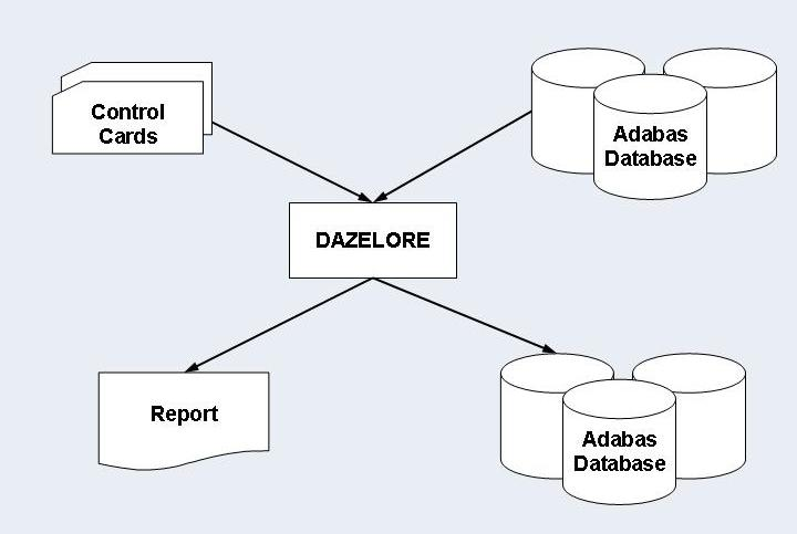
Four different procedures for Steps 8 and 9 - Standard, Simplified,
Special and Turbo - exist (see below). The procedure you should use in any
given case depends on the DBDs and user applications involved. All procedures
involve creating a connect PSB and executing DAZELORE; the
difference is that the Standard procedure requires both the original DL/I and
the converted databases, while the other procedures only require the latter.
The Standard procedure is thus more time-consuming but can be used in all
cases. In contrast, the Simplified, Special and Turbo procedures can only be
used for converted databases in which no logical child segments without
matching logical parents and no variable intersection data segments which are
no longer accessible via their physical parents exist. The Special procedure
differs from the Simplified procedure only for bidirectional logical
relationships. It can only be used if every logical child segment occurrence
has a paired logical child segment occurrence present in the database. For the
Turbo procedure the pre-requisites of the Special procedure must be fulfilled.
Additionally all parent segments on the logical and physical path up to and
including the root segments must have unique sequence fields.
Steps 8 and 9 have to be performed separately for every logical child: i.e. once for every unidirectional logical relationship and twice for every bidirectional logical relationship for both the Standard and the Simplified procedures. The Special and Turbo procedure, however, only needs to be run once per logical relationship, regardless of whether or not this relationship is bidirectional.
When large databases are being converted, performance problems may arise
with these steps. We therefore recommend that you run the DAZELORE
utility in single user mode where possible. In addition, you should use the
Turbo, Special or Simplified methods wherever possible as these procedures do
not require that the original DL/I database be accessed simultaneously. The
highest performance is provided by the Turbo procedure.
Furthermore, the DAZELORE utility may be run using
checkpoints, which means that a particular run may be split up into several
sub-runs if necessary. See the section entitled Restart
Considerations later on in this section for details of how to use
checkpoints with the DAZELORE utility and how to perform
restarts.
This section covers the following topics:
The Standard procedure is required in all cases in which segment occurrences which were originally present in the DL/I database have been physically deleted, but are still accessible via a logical path. This may occur in one of two situations:
With segment occurrences which have been physically deleted but which are still accessible via a logical child segment.
The physical unload performed in the unload procedure does not unload these physically deleted segment occurrences. Logical child segment occurrences may thus be present in the converted database(s), even though no matching logical parent segment occurrences exist (even the parents of these logical parents may be missing). The missing segment occurrences have to be added to the Adabas files in such a way as to be accessible via logical, not physical, paths.
Segment occurrences which are variable intersection data may no longer be accessible via their physical parents but may still be accessible via a logical child segment.
Again, the physical unload performed in the unload procedure does not unload these segment occurrences. The missing segment occurrences have to be added to the Adabas files in such a way that they are only accessible via the logical child.
All missing segments are reinserted during the DAZELORE
runs using the Standard procedure.
The two situations listed above are explained in the set of examples following.
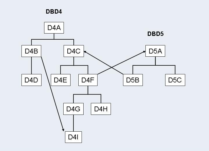
In the example above, the two DBDs, DBD4 and
DBD5, are involved in two logical relationships:
A unidirectional logical relationship between the logical child
segment D4B and the logical parent segment D4I within
DBD4;
A bidirectional logical relationship between DBD4 and
DBD5 with the logical child segments D4F and
D5B and the logical parent segments D4C and
D5A.
Certain segments may be physically deleted but still logically accessible. This depends on the setting of the delete rules for the segments involved in the logical relationships and on the logic of the application programs.
Segments D4A, D4C, D4F,
D4G, and D4I may have been physically deleted but may
still be accessible via the logical child segment D4B. The segment
occurrences will not have been unloaded with DBD4, and will need
to be inserted during the DAZELORE run for D4B.
Segments D4A and D4C may have been physically
deleted but may still be accessible via the logical child segment
D5B. The segment occurrences will not have been unloaded with
DBD4, and will need to be inserted during the
DAZELORE run for D5B.
Segment D5A may have been physically deleted but may still
be accessible via the logical child segment D4F. The segment
occurrences will not have been unloaded with DBD5, and will need
to be inserted during the DAZELORE run for D4F.
In addition, segments D4G, D4H and
D4I may no longer be accessible via their physical parent
D4F, but may still be accessible via D5B. The segment
occurrences will not have been unloaded with DBD4, and will need
to be inserted during the DAZELORE run for D5B.
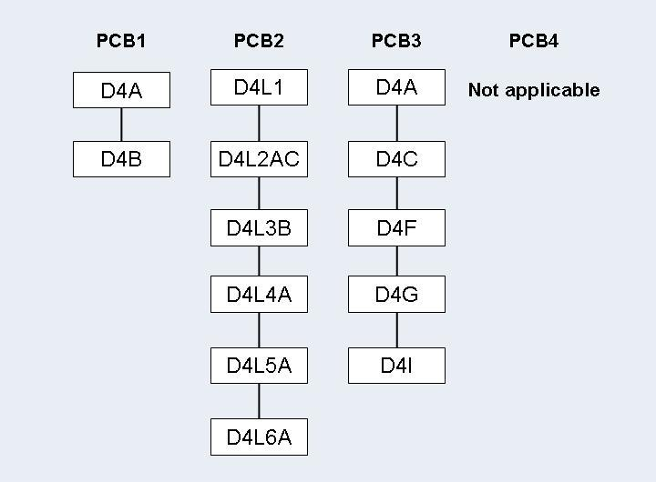
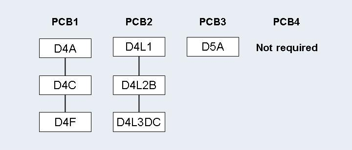
Step 8: Creating a Standard Connect PSB
The Standard connect PSB must contain four PCBs: PCB1, PCB2,
PCB3 and PCB4. All these PCBs must specify processing
option "A". PCB1 and PCB3 must also
specify processing option "P" for path calls.
PCB1 is based on the converted DBD and references the
logical child segment and all its parent segments only. The PCB must be based
on the physical DBD. For this reason, the sensitive segment
(SENSEG) describing the logical child segment cannot describe the
concatenated segment.
PCB2 is based on the converted DBD and references the
logical child segment, all its parent segments, and all the parent segments of
the logical parent in the inverted structure. The PCB has to be based on the
logical DBD. The SENSEG describing the logical child segment must
describe the concatenated segment. Where the logical child segment is a
bidirectional logical child and the paired logical child segment has dependents
(i.e. variable intersection data segments), the latter must be included as
dependents of the logical child as well.
PCB3 is based on the converted DBD and references the
logical parent segment and all its parent segments only. The PCB has to be
based on the physical DBD.
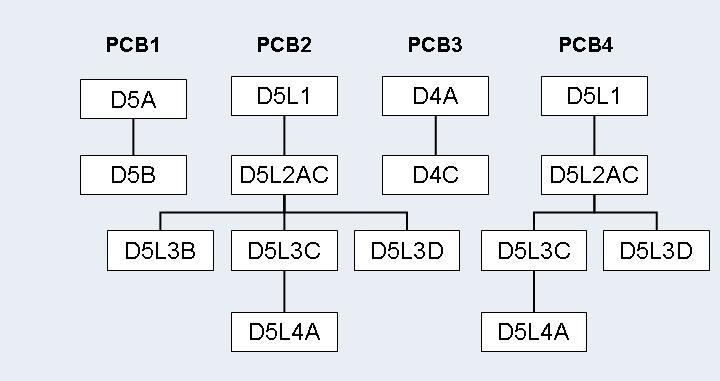
PCB4 is only needed where the logical child segment is a
bidirectional logical child and its paired logical child segment has
dependents. In all other cases it may be omitted. PCB4 is based on
the converted DBD and references the logical child segment and all its parent
segments. It must also reference all variable intersection data segments as
dependents of the logical child. The PCB must be based on the logical DBD. The
SENSEG describing the logical child segment must describe the
concatenated segment.
The Standard connect PSB must be run through the DL/I
PSBGEN and the CBC utility (see the section ADL
Conversion Utilities for DBDs and PSBs in this documentation).
The following figures illustrate this in more detail.
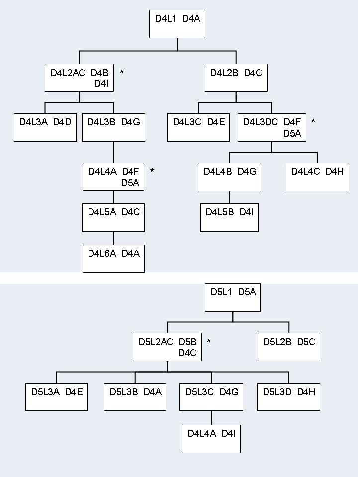
* concatenated segments
Step 9: Establishing Logical Relationship - Standard Procedure
Logical children and parents are connected by running the ADL Establish
Logical Relationships utility, DAZELORE. In the Standard
procedure, DAZELORE is executed as a mixed mode program (see the
section Batch Installation and
Operation in the ADL Interfaces
documentation) using a mixed mode control statement with the following
layout:
ELO,DAZELORE,psbname
where psbname is the name of the Standard connect PSB.
DAZELORE also needs a control statement to indicate which
logical child segment should be connected. The syntax of this control statement
must be as follows:
LC=lognam,MODE=STANDARD
where lognam is the name of the logical child segment in the physical DBD.
The specification of the LC parameter is
mandatory and it must be the first parameter specified.
Where a DBD is involved in more than one logical relationship, several
DAZELORE jobs need to be run. The order for this is only important
where variable intersection data segments exist and at least one of them is a
logical parent. In this case, the DAZELORE run which may cause
variable intersection data segments to be inserted, must be run before the
DAZELORE runs connecting the logical child segments to the
variable intersection data segments which are logical parent segments.
In the case of the examples given on the previous pages, the order in which the jobs have to be run is as follows:
The DAZELORE run for segment D5B.
This is because segment D4I is both a variable
intersection data segment and a logical parent, and during this run
D4I segment occurrences may be inserted.
The order of the two remaining DAZELORE runs (for
D4B and D4F) is irrelevant.
Because segment occurrences may be inserted during
DAZELORE runs, the situation may arise in which logical child
segment occurrences are inserted although the DAZELORE run for the
logical child segment has already been performed. To establish whether this is
the case, look at the report which is printed out at the end of each
DAZELORE run and which gives all the segment occurrences inserted
during that run. If a segment occurrence has been inserted, rerun the
DAZELORE utility for that logical child segment.
For example, let us assume that, in the illustrations given previously,
the DAZELORE runs for D5B and D4F have
been successfully performed. The DAZELORE run for D4B
may have triggered the insertion of D4F segment occurrences. If
this is the case, the DAZELORE run for D4F must be
repeated.
The Simplified and Special procedures may be used in all cases in which the original DL/I database did NOT contain any segment occurrences which have since been physically deleted but which are still accessible via a logical path.
The Special procedure only differs from the Simplified procedure for
bidirectional logical relationships. It can only be used if all logical child
segment occurrences have a matching paired logical child occurrence and vice
versa, i.e. if both logical access paths are always present for any logical
child-logical parent link. This fact has to be ensured by the user, for example
by checking whether the numbers of unloaded records of the paired segments in
the DAZUNDLI report are equal. The special procedure creates the
paired logical child segments in accordance with the information extracted from
the real logical child segment. Note that for the special procedure the logical
child segment for which DAZELORE is run has to be the
real logical child segment.
The advantages of the Special procedure are that the Mass Update step
is not required during loading of the data in Adabas files (see Step 7:
Mass Update for Paired Logical Child Segments ), and that
only one DAZELORE run is needed to establish the bidirectional
logical relationship. This single DAZELORE run also has certain
performance advantages over that used in the Simplified procedure.
If a logical child segment occurrence which does not have a matching logical parent is encountered during the run, the following error message is produced.
ADL0612: Unexpected DP status code for DAZELORE procedure used
The job then terminates. In this case, rerun DAZELORE
using the Standard procedure.
Step 8: Creating a Simplified or Special Connect PSB
Simplified and Special connect PSBs contain a single PCB based on the
converted DBD and referencing the logical child segment and all its parent
segments only. The PCB has to be based on the physical DBD. For this reason,
the SENSEG describing the logical child segment cannot describe
the concatenated segment. This PCB is identical to the PCB1 described in the
section Creating a Standard Connect PSB. It must specify
processing option "AP".
Simplified or Special connect PSBs must be run through the CBC utility (see the section ADL Conversion Utilities for DBDs and PSBs in this documentation).
Step 9: Establishing a Logical Relationship - Simplified or Special Procedure
This is done by running DAZELORE. In the Simplified and
Special procedures, DAZELORE is executed as a normal mode program
(see the section Batch Installation
and Operation in the ADL Interfaces
documentation). The control statement parameters must have the following
layout:
ELO,DAZELORE,psbname
where psbname is the name of the Simplified or Special connect PSB.
DAZELORE also needs a control statement to indicate which
logical child segment should be connected. The syntax of the control statement
for the Simplified procedure is as follows:
LC=lognam,MODE=SIMPLIFIED
and that for the Special procedure is:
LC=lognam,MODE=SPECIAL
where lognam is the name of the logical child segment in the physical DBD.
You may use the sample JCL (JCS) in the member ADLDBC9
(ADLDBC9.J) as an example of a DAZELORE run under
z/OS (z/VSE).
The Turbo procedure is the fastest way to build up the logical relationships. Whenever possible it is recommended to use the Turbo procedure.
The Turbo procedure can only be used if the following issues are satisfied:
The pre-requisites of the Special Procedure are fulfilled. See the previous section for details.
It can only be used for bi-directional logical relationships. Uni-directional relationships are currently not supported.
All parent segments on the logical and physical path up to and including the root segments must have unique sequence fields.
Note that for the Turbo procedure the logical child segment for which
DAZELORE is run has to be the real logical child
segment.
Like the Special procedure, the Mass Update step is not required during
loading of the data in Adabas files (see Step 7: Mass Update for
Paired Logical Child Segments), and only one DAZELORE
run is needed to establish the bidirectional logical relationship.
If a logical child segment occurrence which does not have a matching logical parent is encountered during the run, the following error message is produced.
ADL0612: Unexpected DP status code for DAZELORE procedure used
The job then terminates. In this case, rerun DAZELORE
using the Standard procedure.
The Turbo procedure has the following performance advantages:
It does not read the hierarchy to access the logical child segment data. Instead it uses the ADL internal pointer field to read the child segment data directly.
The ADARUN MULTIFETCH feature can be used, when reading
the logical child segments. It is recommended to use one
MULTIFETCH buffer with maximum size which will contain the
sequential reads of the logical child segment data.
ADL (like DL/I) maintains for each logical child a counter at its
physical parent and at its logical parent. The other procedures update these
counters whenever a logical child is processed. The Turbo procedure updates the
physical parent counter only once when all its children are processed. The
logical parent counters are kept in an online table (“DP counter
table”) and updated at the end of the run. If a counter in the DP
counter table is bigger than 127, the corresponding counter in the database is
updated and the counter is reset. Thus for every 128th logical child the
counter of the logical parent is updated (and not for every logical child).
The update of a logical parent counter in the sequence of the corresponding logical children (as done with the other procedures) is a “random” update and therefore very time consuming because usually every update requires a physical I/O. The Turbo procedure does not only collect the updates (as described before) but it makes also the final update in ISN sequence.
For a better performance it is recommended to use
“RESTART=NO” with the Turbo procedure.
The Turbo connect PSB contains a single PCB based on the converted DBD
and referencing the logical child segment and all its parent segments only
(i.e. same as the Special connect PSB). The PCB has to be based on the physical
DBD. For this reason, the SENSEG describing the logical child
segment cannot describe the concatenated segment. This PCB is identical to the
PCB1 described in the section Creating a Standard Connect
PSB. It must specify processing option "AP".
If RESTART=YES is specified for the DAZELORE
run, the KFB (key-feedback area) length in the PCB must be at
least 8 bytes long. If it is shorter, set it to 8 bytes.
The Turbo connect PSBs must be run through the CBC utility (see the topic ADL Conversion Utilities for DBDs and PSBs in this documentation).

This is done by running DAZELORE. In the Turbo procedure,
DAZELORE is executed as a normal mode program ( see the section
Batch
Installation and Operation in the ADL
Interfaces documentation). The control statement parameters must
have the following layout
ELO,DAZELORE,psbname
where psbname is the name of the Turbo connect PSB.
DAZELORE also needs a control statement to indicate which
logical child segment should be connected. The syntax of the control statement
for the Turbo procedure is as follows:
LC=lognam,MODE=TURBO,MAXDPISN=n
where lognam is the name of the logical child segment in the physical DBD and n is the size of the DP counter table as described later in details.
You may use the sample JCL (JCS) in the member ADLDBC9
(ADLDBC9.J) as an example of a DAZELORE run under
z/OS (z/VSE).
Each DAZELORE run produces a report. Such reports can be
divided into two parts: a first part which is produced before any of the
logical child segments are processed, and a second part which is produced at
the end of a normally terminated run.
The first part of the report has the following layout and contains the following information:
CONNECT LOGICAL CHILD TO ITS LOGICAL PARENT
PROCEDURE........................: procedure
LOGICAL CHILD DBD................: LCDBD
LOGICAL CHILD SEGMENT............: LCseg
LOGICAL PARENT DBD...............: LPDBD
LOGICAL PARENT SEGMENT.......... : LPseg
where
| procedure | is the procedure (Standard, Simplified or Special) used. |
| LCDBD | is the name of the DBD of the logical child segment. |
| LCseg | is the name of the logical child segment. |
| LPDBD | is the name of the DBD of the logical parent segment. |
| LPseg | is the name of the logical parent segment. |
The second part of the report that is produced at the end of a successful run can have a variety of layouts and contain a variety of information.
If, during the processing of a logical child segment,
DAZELORE finds that the destination parent segment has been
physically deleted and subsequently reinserted, the following message is
produced:
PHYSICALLY DELETED SEGMENTS HAVE BEEN REINSERTED
This message is followed by a list of all the segment types and the number of segment occurrences inserted, as shown below.
SEGMENT  QUANTITY
-------  --------
.......  ........
.......  ........
         --------
         ........
Alternatively, if no such situation has been encountered, the following message is produced:
NO PHYSICALLY DELETED SEGMENTS HAVE BEEN FOUND
Where a bidirectional logical child is being processed and the paired logical child segment has dependents (variable intersection data), variable intersection data segments may have been inserted during the run. In this case the following message is produced:
VARIABLE INTERSECTION DATA SEGMENTS HAVE BEEN INSERTED
It is followed by a list of segment types and quantities similar to that mentioned above.
Where no such segments were encountered, the following message is produced:
NO VARIABLE INTERSECTION DATA SEGMENTS HAVE BEEN INSERTED
Where a segment occurrence that is a logical child segment was inserted
during the DAZELORE run, the following eye catcher is printed
behind the segment name and quantity, to indicate that DAZELORE
needs to be rerun for this segment type.
LOGICAL CHILD RE-INSERTED, RE-RUN DAZELORE
The following five messages appear at the end of the report:
THIS RUN PROCESSED .......NO....... LOGICAL CHILDREN
This message states the total number of logical child segment occurrences processed in the run. It is followed by the next message:
OF WHICH .......NO....... LOGICAL CHILDREN WERE ALREADY CONNECTED
which states the total number of logical child segment occurrences found to have been already processed in previous runs.
The third message states the total number of destination parent segment occurrences found to have been physically deleted.
.......NO....... DESTINATION PARENT SEGMENTS WERE FOUND TO BE MISSING
Where the logical child segment being processed is a bidirectional logical child, the message below is produced. It states the total number of paired logical child segment occurrences found to have been physically deleted.
.......NO....... PAIRED LOGICAL CHILD SEGMENTS WERE FOUND TO BE MISSING
The DAZELORE Turbo procedure reports additionally the
highest DP ISN found and how many DP ISNs are bigger than
MAXDPISN.
The following message is produced last.
LOGICAL RELATIONSHIP SUCCESSFULLY ESTABLISHED
The Establish Logical Relationship utility (DAZELORE) may
be run with checkpoints in order to make it restartable by specifying
“RESTART=YES” as DAZELORE parameter. The
number of logical child segment occurrences to be processed before a checkpoint
is taken are defined with the INTER parameter. When
checkpoints are being used and a DAZELORE run is terminated
abnormally, it may be restarted from any checkpoint which has been successfully
issued. The procedure for taking checkpoints and restarting runs is the same as
that used for all normal batch jobs issuing restart and symbolic checkpoint
calls (see the section Recovery and Restart
Procedures in the ADL Interfaces
documentation for more details). For every checkpoint, an Adabas unsynchronized
checkpoint (a C1 call) is taken and a message is written to
DAZOUT1 naming the checkpoint ID. An abnormally terminated
DAZELORE run may be restarted after the Adabas file(s) involved
have been restored to the situation as represented by the checkpoint from which
it is to be restarted. DAZELORE will reposition itself
automatically when restarted from a checkpoint.
A restart is not possible in case of running DAZELORE with
MODE=STANDARD in a z/VSE system.
For extremely long DAZELORE runs, it is possible to limit
the total number of logical child segment occurrences to be processed in one
particular run and to use the restart capabilities to continue processing in a
subsequent run. For this limitation “RESTART=YES” must
be used and both the INTER and the
NUMCP parameters must be specified. As described above,
the INTER parameter specifies the number of logical
child segment occurrences to be processed before a checkpoint is taken whereas
the NUMCP parameter specifies the number of checkpoints
to be written before the program ends. The total number of processed logical
child segment occurrences is therefore the product of both parameters:
NUMCP * INTER. When the
checkpoints specified with the NUMCP parameter are
written, DAZELORE ends. This termination of DAZELORE
does not delete the checkpoint entries in the ADL directory file. This means
that a subsequent DAZELORE run may be restarted from the last
checkpoint without the Adabas files involved being restored, as no Adabas calls
were issued after the last checkpoint. For the restart use
“CPID=cccc” as
DAZIFP parameter where cccc is the last checkpoint
Id.
When all logical child occurrences have been processed,
DAZELORE ends normally and deletes all checkpoints from the ADL
directory.
The additional keyword parameters for DAZELORE may be
specified in the parameter statement as follows:
LC=LCname,MODE=mode,keyword
| Keyword | Explanation | Possible values: | Default: |
|---|---|---|---|
| RESTART |
Specifies whether DAZELORE can be restarted or not. If "YES" is specified, DAZELORE can be restarted. The parameters INTER and NUMCP can be specified. DAZELORE issues XRST and CHKP calls. The ADL Directory file is used in exclusive mode, i.e. no other user can work on it simultaneously. If "NO" is specified, DAZELORE cannot be restarted. In case of an unexpected failure, the utility must be started from the very beginning. The ADL Directory file is not used in exclusive mode. |
YES NO |
YES |
| INTER | Specifies the number of processed logical child
segment occurrences before a checkpoint is issued. The parameter can only be
specified for RESTART=YES. For MODE=TURBO, checkpoints are issued after all
logical child segments belonging to one parent segment have been processed.
That means that the real number of processed logical child segment occurrences
can be slightly higher than specified with the INTER
parameter.
|
1 - 2147483647 |
2147483647 |
| NUMCP | Specifies the number of checkpoints issued by
DAZELORE. As soon as DAZELORE has reached this number, it is stopped and can be
restarted later. At the restart the last checkpoint Id must be given as DAZIFP
CPID parameter. The NUMCP parameter can only be
specified for RESTART=YES and if the INTER parameter has
been specified. The total number of processed logical child segment occurrences
is: NUMCP * INTER.
|
1 - 2147483647 |
1 |
| MAXDPISN | Specifies the length (in bytes) of the table of the destination parent (DP) counters (the destination parent is the logical parent in the logical relationship). As far as possible the table should be as big as the maximum ISN of the destination parent data. The counters of DPs with ISNs higher than MAXDPISN are updated immediately and lead therefore to a poorer performance. The report of DAZELORE outlines the highest DP ISN found and how many DP ISNs are bigger than MAXDPISN. The REGION/PARTITION of the job should be adjusted accordingly so that the table can be allocated. This parameter can only be specified for MODE=TURBO. |
1 - 16777215 |
65536 |
Where the total number of logical child segment occurrences is 5,312,726, and it has been decided to process them in 3 runs, with a checkpoint to be taken every 10,000th logical child segment occurrence, the following parameter setting is required:
| run | INTER | NUMCP | Processed LCs |
|---|---|---|---|
| 1 | 10,000 | 200 | 2,000,000 |
| 2 | 10,000 | 200 | 2,000,000 |
| 3 | 10,000 | 200 | 1,312,726 |
The following examples illustrate the z/OS JCL requirements for the
utility runs described in this section. They include the requirements for the
DAZUNDLI, DAZUNLOD and DAZREFOR utilities, for the
ADACMP step during data loading, and for
DAZELORE.
The table below lists the data sets used by the Unload utility,
DAZUNDLI.
| DDname | Medium | Description |
|---|---|---|
| DAZIN1 | Reader | Control input for DAZUNDLI. * |
| DAZIN2 | Reader | Control input for batch monitor in mixed mode. |
| DAZIN3 | Tape/Disk | Root sequence field values. ** |
| DAZOUT1 | Printer | Report, messages and codes. |
| DAZOUT3 | Tape/Disk | The unloaded database. |
* Set to dummy if no keyword is specified.
** Only required if the ROOTKEYS=SEQ is set.
//UNDLI      EXEC DLIBATCH,PSB=PSB4CON,MBR=DAZIFP          (1)
//STEPLIB    DD
//           DD
//           DD   DSN=ADLvrs.LOAD,DISP=SHR
//           DD   DSN=ADABAS.LOAD,DISP=SHR
//*
//* DATASETS DESCRIBING DL/I DATABASES
//*
//G.file     DD   ...
//*
//* ADARUN CARDS
//*
//G.DDCARD   DD   *
ADARUN PROGRAM=USER,...
//*
//* ADABAS DL/I BRIDGE DATASETS
//*
//G.DAZIN1   DD *
MODE=CHECKNUM
//G.DAZIN2   DD   *
UNL,DAZUNDLI,PSB4CON
//G.DAZOUT1  DD   SYSOUT=X
//G.DAZOUT3  DD   DSN=ADL.DBD4.UNLOAD,DISP=OLD
(1) The standard batch procedure provided by IBM as part of the IMS/DB installation.
The following table lists the data sets used by the Unload utility,
DAZUNLOD.
| DDname | Medium | Description |
|---|---|---|
| DAZOUT1 | Printer | Report, messages and codes. |
| DAZOUT3 | Tape/Disk | The unloaded database. |
//UNLOD      EXEC DLIBATCH,PSB=PSB4CON,MBR=DAZUNLOD        (1)
//G.STEPLIB  DD
//           DD
//           DD   DSN=ADLvrs.LOAD,DISP=SHR
//*
//* DATASETS DESCRIBING DL/I DATABASES
//*
//G.file     DD   ...
//*
//* ADABAS DL/I BRIDGE DATASETS
//*
//G.DAZOUT1  DD   SYSOUT=X
//G.DAZOUT3  DD   DSN=ADL.DBD4.REFOR,DISP=OLD
(1) The standard batch procedure provided by IBM as part of the IMS/DB installation.
The following table lists the data sets used by the Reformat utility,
DAZREFOR.
| DDname | Medium | Description |
|---|---|---|
| DAZIN3 | Tape/Disk | The data to be reformatted. |
| DAZOUT1 | Printer | Report, messages and codes. |
| DAZOUT3 | Tape/Disk | The unloaded database. |
//REFOR      EXEC PGM=DAZIFP,PARM='REF,DAZREFOR,PSB4CON'
//STEPLIB    DD   DSN=ADLvrs.LOAD,DISP=SHR
//           DD   DSN=ADABAS.LOAD,DISP=SHR
//DAZIN3     DD   DSN=ADL.DBD4.REFOR,DISP=OLD
//DAZOUT1    DD   SYSOUT=X
//DAZOUT2    DD   SYSOUT=X
//DAZOUT3    DD   DSN=ADL.DBD4.UNLOAD,DISP=OLD
//DDCARD     DD   *
ADARUN PROGRAM=USER,...
The table below lists the data sets used during the first step of the
data loading process, which uses the Adabas Compression utility,
ADACMP.
| DDname | Medium | Description |
|---|---|---|
| DAZIN1 | Reader | Control input for the Adabas User Exit 6, DAZUEX06. |
| DAZOUT1 | Printer | Report, messages and codes. |
ADACMP run for an initial load of DBD4 on DBID=9,FNR=34
//ADACMP   EXEC PGM=ADARUN
//STEPLIB  DD   DSN=ADABAS.LOAD,DISP=SHR
//         DD   DSN=ADLvrs.LOAD,DISP=SHR
//DDEBAND  DD   DSN=ADL.DBD4.UNLOAD,DISP=OLD
//DDAUSBA  DD   DSN=ADL.DBD4.LOAD,DISP=OLD
//DDFEHL   DD   DSN=&&FEHL,UNIT=SYSDA,SPACE=(CYL,(1,1)),DISP=(,PASS)
//DDDRUCK  DD   SYSOUT=X
//DDPRINT  DD   SYSOUT=X
//DDCARD   DD   *
ADARUN PROGRAM=ADACMP,DB=9,SVC=svc,DE=3390,UEX6=I00034
//DDKARTE  DD   *                            (1)
ADACMP USERISN
ADACMP FNDEF='01,Z0,A,DE,MU,UQ,NU'                       Z1 INVERTED (INSERT LAST)
ADACMP FNDEF='01,Z1,A,DE,MU,UQ,NU'                       MAIN DESCRIPTOR FIELD UP22
ADACMP FNDEF='01,Z2,004,B,NU'                            ROOT ISN (NON ROOT SEGS)
.
.
/*
//DAZIN1   DD   *
FNR=034,MODE=LOAD
//DAZOUT1  DD   SYSOUT=X
//*
//         EXEC PGM=IEBGENER
//SYSPRINT DD   SYSOUT=X
//SYSUT1   DD   DSN=&&FEHL,DISP=(OLD,DELETE)
//SYSUT2   DD   SYSOUT=X
//SYSIN    DD   *
/*
(1) The ADACMP statements generated by the
CBC utility as member W00034.
ADACMP run for a mass update of the logical child D5B
//ADACMP   EXEC PGM=ADARUN
//STEPLIB  DD   DSN=ADABAS.LOAD,DISP=SHR
//         DD   DSN=ADLvrs.LOAD,DISP=SHR
//DDEBAND  DD   DSN=ADL.DBD5.UNLOAD,DISP=OLD
//DDAUSBA  DD   DSN=ADL.DBD4.MASS,DISP=OLD
//DDFEHL   DD   DSN=&&FEHL,UNIT=SYSDA,SPACE=(CYL,(1,1)),DISP=(,PASS)
//DDDRUCK  DD   SYSOUT=X
//DDPRINT  DD   SYSOUT=X
//DDCARD   DD   *
ADARUN PROGRAM=ADACMP,DB=9,SVC=svc,DE=3390,UEX6=I00035
//DDKARTE  DD   *                            (1)
ADACMP FNDEF='01,Z0,A,DE,MU,UQ,NU'                       Z1 INVERTED (INSERT LAST)
ADACMP FNDEF='01,Z1,A,DE,MU,UQ,NU'                       MAIN DESCRIPTOR FIELD UP22
ADACMP FNDEF='01,Z2,004,B,NU'                            ROOT ISN (NON ROOT SEGS)
.
.
/*
//DAZIN1   DD   *
FNR=034,LC=D5B,MODE=MASS
//DAZOUT1  DD   SYSOUT=X
//*
//         EXEC PGM=IEBGENER
//SYSPRINT DD   SYSOUT=X
//SYSUT1   DD   DSN=&&FEHL,DISP=(OLD,DELETE)
//SYSUT2   DD   SYSOUT=X
//SYSIN    DD   *
/*
(1) The ADACMP statements generated by the
CBC utility as member W00034 without the
USERISN option.
The table below lists the data sets used by the Establish Logical
Relationship utility, DAZELORE.
| DDname | Medium | Description |
|---|---|---|
| DAZIN1 | Reader | Control input for DAZELORE and for the batch monitor in normal mode. |
| DAZIN2 | Reader | Control input for the batch monitor in mixed mode. * |
| DAZOUT1 | Printer | Report, messages and codes. |
* Only required if DAZELORE is run in mixed
mode, i.e. when MODE=STANDARD is specified for the conversion of
an original DL/I database.
DAZELORE run with MODE=STANDARD
//ELORE      EXEC DLIBATCH,PSB=PSB4BI,MBR=DAZIFP    (1)
//G.STEPLIB  DD
//           DD
//           DD   DSN=ADLvrs.LOAD,DISP=SHR
//           DD   DSN=ADABAS.LOAD,DISP=SHR
//*
//* DATASETS DESCRIBING DL/I DATABASES DBD4 AND DBD5
//*
//G.FILE     DD   ...
//*
//* ADARUN CARDS
//*
//G.DDCARD   DD   *
ADARUN PROGRAM=USER,...
//*
//* ADABAS DL/I BRIDGE DATASETS
//*
//G.DAZIN1   DD   *
LC=D4F,MODE=STANDARD
//G.DAZIN2   DD   *
ELO,DAZELORE,PSB4BI
//G.DAZOUT1  DD   SYSOUT=X
(1) The standard batch procedure provided by IBM as part of the IMS/DB installation.
DAZELORE run with MODE=TURBO
//       EXEC PGM=DAZIFP,PARM='ELO,DAZELORE,INSTELO'
//STEPLIB  DD DSN=ADLvrs.LOAD,DISP=SHR
//         DD DSN=ADABAS.LOAD,DISP=SHR
//DAZOUT1  DD SYSOUT=X
//DDCARD   DD *
ADARUN PROGRAM=USER,...
//DAZIN1   DD *
LC=COURSEP,MODE=TURBO,RESTART=NO,MAXDPISN=5000000
The following examples illustrate the JCS requirements for the utility
runs described in this section. They include the requirements for the
DAZUNDLI, DAZUNLOD and DAZREFOR
utilities, for the ADACMP step during data loading, and for
DAZELORE.
The following table lists the files used by the Unload utility,
DAZUNDLI, in mixed mode.
| DTF | Logical Unit | Medium | Description |
|---|---|---|---|
| DAZIN1 | SYSIPT | Reader | Control input for DAZUNDLI. * |
| DAZIN2 | SYSIPT | Reader | Control input for batch monitor. |
| DAZIN3D | SYS014 | Disk | Root seq. field value **/*** |
| DAZIN3T | SYS014 | Tape | Root seq. field value **/*** |
| DAZOUT1 | SYSLST | Printer | Report, messages and codes. |
| DAZOT3D | SYS013 | Disk | The unloaded database. ** |
| DAZOT3T | SYS013 | Tape | The unloaded database. ** |
* Only required if any keyword has been specified.
** Only one of either disk or tape is required. The logical
unit indicated is the default logical unit. To change it, specify the
SQ parameter either in the ADL parameter module or as a
dynamic parameter, for example: SQ=(5,)
*** Only required if the ROOTKEYS=SEQ keyword
has been specified.
The control input for the batch monitor (DAZIFP), for
ADARUN, for DAZUNDLI, and for the DL/I initialization
program, DLZRRC00, are all read from SYSIPT. The
control statements must be specified in the following order:
DLI,DAZIFP,psbname,...                      input for DLZRRC00
UNL,DAZUNDLI,psbname,...                    input for DAZIFP
ADARUN DB=dbid,MO=MULTI,PROGRAM=USER,...    input for ADARUN
/*
MODE=CHECKNUM                               input for DAZUNDLI
DAZUNDLI run unloading a database on disk
// ASSGN SYS013,DISK,VOL=volser,SHR
// DLBL DAZOT3D,'ADL.DBD4.UNLOAD,0,SD'
// EXTENT SYS013,volser,1,0,.......
// EXEC DLZRRC00
DLI,DAZIFP,PSB4CON
UNL,DAZUNDLI,PSB4CON
ADARUN PROGRAM=USER,...
/*
DAZUNDLI run unloading a database on tape
// ASSGN SYS005,TAPE
// TLBL DAZOT3T,'ADL.DBD4.UNLOAD,0,SD'
// EXEC DLZRRC00
DLI,DAZIFP,PSB4CON
UNL,DAZUNDLI,PSB4CON,SQ=(5,)
ADARUN PROGRAM=USER,...
/*
The table below lists the files used by the Unload utility,
DAZUNLOD.
| DTF | Logical Unit | Medium | Description |
|---|---|---|---|
| DAZOUT1 | SYSLST | Printer | Report, messages and codes. |
| DAZOT3D | SYS014 | Disk | The unloaded database. * |
| DAZOT3T | SYS014 | Tape | The unloaded database. * |
* Only one of the two is required. The logical unit indicated
is the default logical unit. To change it, specify the
SQ parameter either in the ADL parameter module or as a
dynamic parameter, for example: SQ=(5,)
// ASSGN SYS013,DISK,VOL=volser,SHR
// DLBL DAZOT3D,'ADL.DBD4.REFOR,0,SD'
// EXTENT SYS013,volser,1,0,.......
// EXEC DLZRRC00
DLI,DAZUNLOD,PSB4CON
/*
The following table lists the files used by the Reformat utility,
DAZREFOR.
| DTF | Logical Unit | Medium | Description |
|---|---|---|---|
| DAZIN1 | SYSIPT | Reader | Control input for batch monitor. |
| DAZOUT1 | SYSLST | Printer | Report, messages and codes. |
| DAZIN3D | SYS014 | Disk | The unloaded database. * |
| DAZIN3T | SYS014 | Tape | The unloaded database. * |
| DAZOT3D | SYS013 | Disk | The unloaded database. * |
| DAZOT3T | SYS013 | Tape | The unloaded database. * |
* Only one of either tape or disk is required. The logical
unit indicated is the default logical unit. To change it, specify the
SQ parameter either in the ADL parameter module or as a
dynamic parameter, for example: SQ=(5,)
The control input for the batch monitor (DAZIFP) and for
ADARUN is read from SYSIPT. The control statements
must be specified in the following order:
REF,DAZREFOR,psbname,...                                             input for DAZIFP
ADARUN DB=dbid,MO=MULTI,PROGRAM=USER,...    input for ADARUN
/*
// ASSGN SYS014,DISK,VOL=volser,SHR
// DLBL DAZIN3D,'ADL.DBD4.REFOR,0,SD'
// EXTENT SYS014,volser,1,0,.......
// ASSGN SYS013,DISK,VOL=volser,SHR
// DLBL DAZOT3D,'ADL.DBD4.UNLOAD,0,SD'
// EXTENT SYS013,volser,1,0,.......
// EXEC DAZIFP
REF,DAZREFOR,PSB4CON
ADARUN PROGRAM=USER,...
/*
The table below lists the files used during the first step of the data
loading process, which uses the Adabas Compression utility,
ADACMP.
| DTF | Logical Unit | Medium | Description |
|---|---|---|---|
| DAZIN1 | SYSIPT | Reader | Control input for the Adabas User Exit 6, DAZUEX06. |
| DAZOUT1 | SYSLST | Printer | Report, messages and codes. |
The control input for the Adabas User Exit 6, DAZUEX06,
for ADARUN and for the Adabas Compression utility,
ADACMP, are all read from SYSIPT. The control
statements must be specified in the following order:
ADARUN DB=dbid,MO=MULTI,PROGRAM=ADACMP    input for ADARUN
/*
ADACMP USERISN,RECFM=VB,LRECL=8196        input for ADACMP
ADACMP FNDEF='01,Z0,.....'
.
.
/*
FNR=fnr,MODE=LOAD                         input for DAZUEX06
/*
ADACMP run for an initial load of DBD4, DBID=9,FNR=34
// ASSGN SYS010,DISK,VOL=volser,SHR
// DLBL EBAND,'ADL.DBD4.UNLOAD,0,SD'
// EXTENT SYS010,volser,1,0,.......
// ASSGN SYS012,DISK,VOL=volser,SHR
// DLBL AUSBA,'ADL.DBD4.LOAD,0,SD'
// EXTENT SYS012,volser,1,0,.......
// ASSGN SYS014,IGN
// EXEC PROC=ADLLIBS
// EXEC ADARUN,SIZE=4K
ADARUN PROGRAM=ADACMP,SVC=svc,DE=3390,UEX6=I00034
/*
ADACMP USERISN,LRECL=8196,RECFM=VB           (1)
ADACMP FNDEF='01,Z0,A,DE,MU,UQ,NU'                       Z1 INVERTED (INSERT LAST)
ADACMP FNDEF='01,Z1,A,DE,MU,UQ,NU'                       MAIN DESCRIPTOR FIELD
ADACMP FNDEF='01,Z2,003,B,NU'                                    ROOT ISN (NON ROOT SEGS)
.
.
/*
FNR=034,MODE=LOAD
/*
(1) The ADACMP statements generated by the
CBC utility as member W00034.
ADACMP run for a mass update of the logical child D5B
// ASSGN SYS010,DISK,VOL=volser,SHR
// DLBL EBAND,'ADL.DBD5.UNLOAD,0,SD'
// EXTENT SYS010,volser,1,0,.......
// ASSGN SYS012,DISK,VOL=volser,SHR
// DLBL AUSBA,'ADL.DBD4.MASS,0,SD'
// EXTENT SYS012,volser,1,0,.......
// ASSGN SYS014,IGN
// EXEC PROC=ADLLIBS
// EXEC ADARUN,SIZE=4K
ADARUN PROGRAM=ADACMP,SVC=svc,DE=3390,UEX6=I00034
/*
ADACMP LRECL=8196,RECFM=VB (1)
ADACMP FNDEF='01,Z0,A,DE,MU,UQ,NU'      Z1 INVERTED (INSERT LAST)
ADACMP FNDEF='01,Z1,A,DE,MU,UQ,NU'      MAIN DESCRIPTOR FIELD
ADACMP FNDEF='01,Z2,003,B,NU ROOT'      ISN (NON ROOT SEGS)
.
.
/*
FNR=34,MODE=MASS,LC=D5B
/*
(1) The ADACMP statements generated by the
CBC utility as member W00034 without the
USERISN option.
The following table lists the files used by the Establish Logical
Relationship utility, DAZELORE.
| DTF | Logical Unit | Medium | Description |
|---|---|---|---|
| DAZIN1 | SYSIPT | Reader | Control input for DAZELORE and for the batch monitor in normal mode. |
| DAZIN2 | SYSIPT | Reader | Control input for the batch monitor in mixed mode. * |
| DAZOUT1 | SYSLST | Printer | Report, messages and codes. |
* Only required if DAZELORE is run in mixed
mode, i.e. when MODE=STANDARD is specified for the conversion of
an original DL/I database.
The control input for the batch monitor, DAZIFP, for
DAZELORE itself, for ADARUN and for the DL/I
initialization program, DLZRRC00, is read from
SYSIPT. The control statements must be specified in the following
order:
DLI,DAZIFP,psbname,...                     input for DLZRRC00 *
ELO,DAZELORE,psbname,...                   input for batch monitor
/*
ADARUN DB=dbid,MO=MULTI,PROGRAM=USER,...   input for ADARUN
/*
LC=lcname,MODE=STANDARD                    input for DAZELORE
/*
* Only required when DAZELORE is run in mixed mode.
DAZELORE run with MODE=STANDARD
// EXEC DLZRRC00
DLI,DAZIFP,PSB4CON
ELO,DAZELORE,PSB4CON
/*
ADARUN PROGRAM=USER,...
/*
LC=D4F,MODE=STANDARD
/*
DAZELORE run with MODE=TURBO
// EXEC DAZIFP
ELO,DAZELORE,INSTELO
/*
ADARUN PROGRAM=USER,...
/*
LC=COURSEP,MODE=TURBO,RESTART=NO,MAXDPISN=5000000
/*