This section describes the CST-Panel model, which is used to create the client modify (maintenance) subprogram for a model. The model-generated specification panels run as part of a common wizard in the Construct Program Generation plug-in for Natural for Windows.
This section covers the following topics:
To enable a Natural Construct model for the Construct Program Generation plug-in, you must first determine how many panels will be used for the wizard and what information will be presented on each panel. In most cases, the panels will follow a one-to-one relationship with the corresponding modify server panels generated by the CST-Modify model.
The CST-Panel model generates one column of GUI controls per panel. Each column contains a label and control for editing a model specification panel. For greater flexibility, you can include additional controls within user exits. Alternately, you can create your own wizard instead of using the supplied common wizard. (In this case, you will not use the CST-Panel model.)
Note:
The CST-Panel model is only available in the Construct Program
Generation plug-in for Natural for Windows. This
model is not available in the Natural Construct character interface
(NCSTG).
Use the CST-Panel model to generate the client modify (maintenance) subprogram for your model.
After specifying the required parameters on one panel, select Next to proceed to the next panel. To generate the module, select Finish on the last specification panel.
The CST-Panel model has two specification panels:
The following example shows the Standard Parameters panel for CST-Panel:
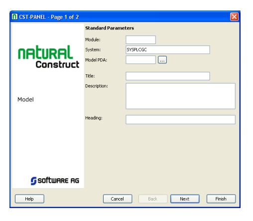
Use this panel to define standard parameters for your wizard, such as the name of the generated subprogram and the heading displayed at the top of the wizard panel.
The input fields on this panel are:
| Field | Description |
|---|---|
| Module | Name of the Natural subprogram (module) to
generate.
Module names use the following naming convention: WCNxxMy where xx is the unique identifier for your model and y is letter from A–J that identifies the maintenance panel (A for the first panel, B for the second, etc.). For more information, see Naming Conventions for Model Components. |
| System | Name of the system (by default, the name of the
current library).
The system name must be alphanumeric, not exceed 32 characters in length, and does not have to be associated with a Natural library ID. (The combination of the module name and system name is used as a key to access help information for the generated subprogram.) |
| Model PDA | Name of the parameter data area (PDA) for your model. |
| Title | Title for the generated subprogram. The title identifies the subprogram for the List Generated Modules function on the Generation main menu and is used internally for program documentation. |
| Description | Brief description of the subprogram. The description is inserted in the banner at the beginning of the subprogram and is used internally for program documentation. |
| Heading | Heading displayed at the top of the generated wizard panel. For example, Standard Parameters. |
The following example shows Additional Parameters for CST-Panel:
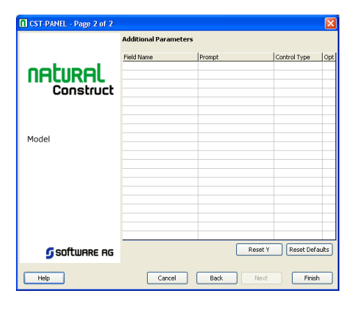
Use this panel to position the GUI controls for your wizard panel in a single column. Each row in the grid above represents one field in the column and one label for each field.
The input fields on this panel are:
| Field | Description |
|---|---|
| Field Name | Name of a #PDA or #PDAX variable field in your
model PDA or the name of a field in CU--PDA. To select the field from a list of
fields in the model PDA, select .
Note: |
| Prompt | Text used as a label for the field. A TEXTCONSTANT Natural GUI control is generated for each control. The string is based on the value entered in this field. Only the TOGGLEBUTTON (or checkbox) control does not have an extra control generated, as this control includes its own label. |
| Control Type | Type of Natural GUI control to use. Select one of the following: INPUTFIELD TOGGLEBUTTON EDITAREA SELECTIONBOX |
| Opt | To modify the size and location attributes for GUI controls, click the … button. The Optional Parameters window is displayed. For a description of this window, see Reset Default Size and Location Variables. |
You can reset and reassign the default Y-coordinate values for GUI controls. Use this option when you have customized the default Y value and want to restore the default.
![]() To reset and reassign the default Y-Coordinate values:
To reset and reassign the default Y-Coordinate values:
Select .
You can customize the size and location-related attributes for GUI controls.
![]() To customize the size and location-related attributes:
To customize the size and location-related attributes:
Select .
The Optional Parameters window is displayed. For example:
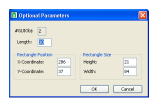
Change the current size and location-related attributes.
The input fields in this window are:
| Field | Description |
|---|---|
| #GUIObj | Identifier for the current GUI object. |
| Length | Maximum number of characters that can be entered as input for the specified GUI control. This field applies to EDITAREA and INPUTFIELD controls only. |
| X-Coordinate | X coordinate value for the GUI control. |
| Y-Coordinate | Y coordinate value for the GUI control.
Note: |
| Height | Height of the GUI control in pixels. |
| Width | Width of the GUI control in pixels. |
Select .
The following example shows the User Exit Browser panel for the CST-Panel model:
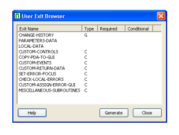
This section describes the model-specific user exits on this panel. For information about the common user exits on this panel, see Supplied User Exits. For information about using the User Exit editor, see User Exit Editor, Natural Construct Generation.
Note:
For more information about the model-specific user exits, see the
examples and notes in the sample code generated for each exit.
The model-specific user exits for CST-Panel are:
Use this exit to check for local validation errors on wizard panels. Local errors are detected when the user selects , but before the model’s validation subprogram is called. If a local validation error occurs, the error is displayed to the user and or becomes inactive.
Note:
Local validations do not occur when the user selects
.
Use this exit to copy additional fields from the model PDA to GUI controls.
Use this exit in combination with the SET-ERROR-FOCUS exit to set focus to custom GUI controls when a validation error is detected.
Use this exit to add additional GUI controls to your wizard panel. For each new control, note the number of the last GUIOBJ (GUI object) used by the last generated control and increment by 1.
Use this exit to handle events for custom GUI controls on the wizard panel. For example, you can use this exit to add a button to the wizard panel and write code to respond to a click event. When a user selects the button, a window is invoked to display additional lookup data.
Use this exit to copy any additional GUI control values to the model PDA or CU--PDA data areas.
Use this exit in combination with the CUSTOM-ASSIGN-ERROR-GUI exit to set focus to custom GUI controls when a validation error is detected.